


目录
题目
题目要求及分析
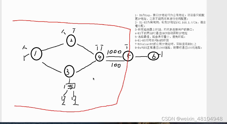
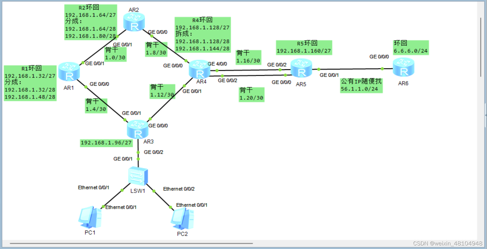
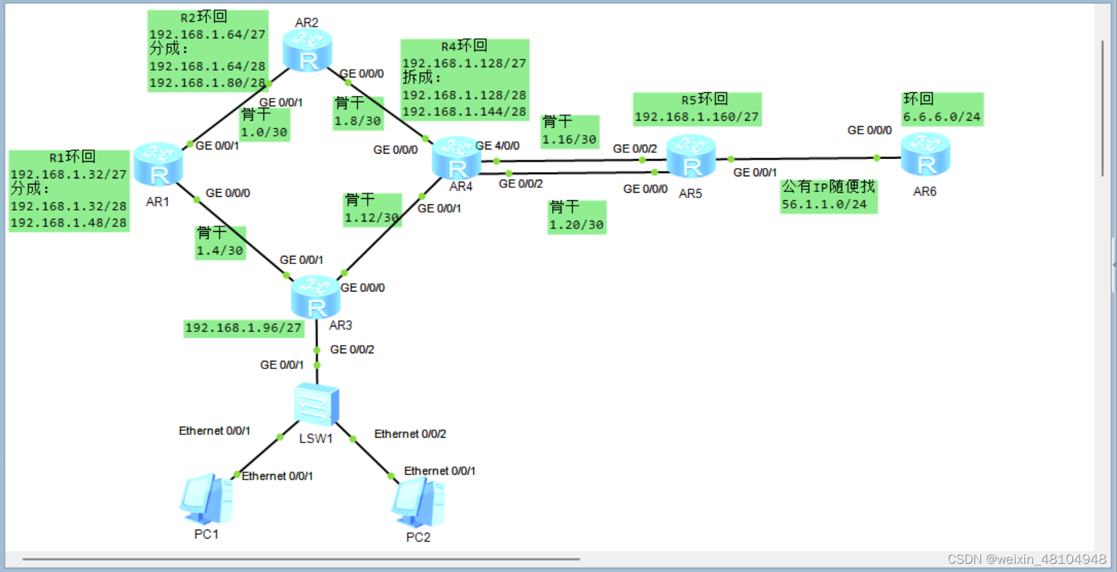
1,R6为ISP(网络服务提供商),接口只配IP地址
意思就是,R6左边就是个简单的局域网,把R6想成是运营商的路由器2,R1到R5为局域网,私有IP地址192.168.1.0/24,合理分配
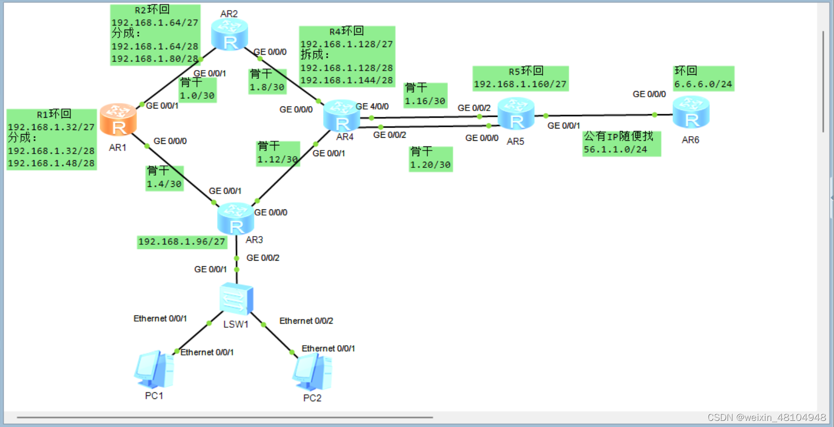
根据192.168.1.0/24这个网段进项子网划分:

分析:
    R1,R2,R4上都有两个环回接口;R3下连的是交换机,交换机下再连2台点电脑;相当于R1,R2,R4需要6个IP地

    址,R3需要一个IP地址

    为了便于汇总,便于管理,可以只给R1,R2,R4分别分配一个网段,各自下去在子网划分

    就是所有的路由器(1-5)上的接口一共需要5个网段


    路由器间的链路也要网段,不算R5和R6间的链路,就一共需要6个网段,还是一样,便于管理,可以将这些

    所有的链路需要的网段看成需要一个网段,然后这一个网段再去给这些链路分配

    目前就需要从192.168.1.0/24中划分出,6个网段

    其中有的网段再划分用于分配给环回和各个链路

    192.168.1.0 24 向主机位借3位,2^3=8,划分成了8个网段,剩下的2个网段,在现实中不算浪费,用于

    升级

    128 64 32 16 8 4 2 1

    192.168.1.0 24
    11000000,10101000,00000001,00000000


                            128 64 32
    11000000,10101000,00000001,000 00000    192.168.1.0 27 再分用于分配给6条链路

                                         16 8 4
            11000000,10101000,00000001,000 000 00    1.0/30
            11000000,10101000,00000001,000 001 00    1.4/30
            11000000,10101000,00000001,000 010 00    1.8/30
            11000000,10101000,00000001,000 011 00    1.12/30
            11000000,10101000,00000001,000 100 00    1.16/30
            11000000,10101000,00000001,000 101 00    1.20/30

            11000000,10101000,00000001,000 110 00    1.24/30
            11000000,10101000,00000001,000 111 00    1.28/30


                            128 64 32
    11000000,10101000,00000001,001 00000    1.32 27--->R1
                                        32 16
            11000000,10101000,00000001,001 0 0000    1.32/28
            11000000,10101000,00000001,001 1 0000    1.48/28

    11000000,10101000,00000001,010 00000    1.64 27--->R2
                                       64 16
            11000000,10101000,00000001,010 0 0000    1.64/28
            11000000,10101000,00000001,010 1 0000    1.80/28

    11000000,10101000,00000001,011 00000    1.96 27--->R3

    11000000,10101000,00000001,100 00000    1.128 27--->R4
                                      128  16
            11000000,10101000,00000001,100 0 0000    1.128/28
            11000000,10101000,00000001,100 1 0000    1.144/28

    11000000,10101000,00000001,101 00000    1.160 27--->R5

    11000000,10101000,00000001,110 00000    1.192 27
    11000000,10101000,00000001,111 00000    1.224 27
192.168.1.0/24
128 64 32 16 8 4 2 1
192.168.1.0/27 16 8 4
192.168.1.0/30 1.000 000 00--1.000 000 11==>1.0->1.3 可用的IP就是1.1和1.2
192.168.1.4/30 1.000 001 00--1.000 001 11==>1.4->1.3 可用的IP就是1.5和1.6
192.168.1.8/30 1.000 010 00--1.000 010 11==>1.8->1.3 可用的IP就是1.9和1.10
192.168.1.12/30 1.000 011 00--1.000 011 11==>1.12->1.3 可用的IP就是1.13和1.14
192.168.1.16/30 1.000 100 00--1.000 100 11==>1.16->1.3 可用的IP就是1.17和1.18
192.168.1.20/30 1.000 101 00--1.000 101 11==>1.20->1.3 可用的IP就是1.21和1.22
192.168.1.32/27 R1
192.168.1.32/28 可用:1.33-1.46
192.168.1.48/28 可用:1.49-1.62
192.168.1.64/27 R2
192.168.1.64/28 可用:1.65-
192.168.1.80/28 可用:1.81-
192.168.1.96/27 R3
192.168.1.128/27 R4
192.168.1.128/28 129-
192.168.1.144/28 145-
192.168.1.160/27 R5 161-
3,所有路由器上的环回均代表连接用户的接口
4,R3下的pc通过DHCP自动获取IP
需要开启R3的dhcp服务5,选路最佳,路由表小,避免环路
缺省路由可以解决,缺省路由不去的路或者不是最佳的路由,这就需要在各个路由器上加6,R1到R5均可访问R6的环回
7,R4,R5正常通过1000兆链路,故障通过100兆链路
备用链路是100兆拓扑图
配各个路由器的环回
R1 2个环回接口
<Huawei>sys
[huawei]sus R1
[R1]int lo0
[R1-LoopBack0]ip add 192.168.1.33 28
[R1-LoopBack0]int lo1
[R1-LoopBack1]ip add 192.168.1.49 28
[R1-LoopBack1]
R2 2个环回
The device is running!

<Huawei>sys
Enter system view, return user view with Ctrl+Z.
[Huawei]sys R2
[R2]int lo0
[R2-LoopBack0]ip add 192.168.1.65 28
[R2-LoopBack0]int lo1
[R2-LoopBack1]ip add 192.168.1.81 28
[R2-LoopBack1]
R3配置接口
给R3的接口配IP,千万不要配成,192.168.1.96 27,这个是网段,这个网段可用的IP(除去主机位全0和全1)是1.97-1.126
192.168.1.96/27

128 64 32 16 8 4 2 1

11000000,10101000,00000001,011 00000  27 1.96/27

                                ...

                           011  11111 27  1.127/27
1.97-1.126
The device is running!
<Huawei>sys
Enter system view, return user view with Ctrl+Z.
[Huawei]sys R3
[R3]int g 0/0/2
[R3-GigabitEthernet0/0/2]ip add 192.168.1.97 27
Jan 18 2022 02:14:04-08:00 R3 %%01IFNET/4/LINK_STATE(l)[0]:The line protocol IP
on the interface GigabitEthernet0/0/2 has entered the UP state.
[R3-GigabitEthernet0/0/2]R4 2个环回
The device is running!

<Huawei>sys
Enter system view, return user view with Ctrl+Z.
[Huawei]sys R4
[R4]in tlo0
       ^
Error: Wrong parameter found at '^' position.
[R4]in lo0
[R4-LoopBack0]ip add 192.168.1.129 28
[R4-LoopBack0]int lo1
[R4-LoopBack1]ip add 192.168.1.145 28
[R4-LoopBack1]
R5一个环回
The device is running!

<Huawei>sys
Enter system view, return user view with Ctrl+Z.
[Huawei]sys R5
[R5]int lo0
[R5-LoopBack0]ip add 192.168.1.161 27
[R5-LoopBack0]
R6一个环回,公有IP
The device is running!

<Huawei>sys
Enter system view, return user view with Ctrl+Z.
[Huawei]sys R6
[R6]int lo0
[R6-LoopBack0]ip add 6.6.6.6 24
[R6-LoopBack0]
配各个骨干链路
R1
[R1]int g 0/0/1
[R1-GigabitEthernet0/0/1]ip add 192.168.1.1 30
Jan 18 2022 02:21:06-08:00 R1 %%01IFNET/4/LINK_STATE(l)[0]:The line protocol IP
on the interface GigabitEthernet0/0/1 has entered the UP state.
[R1-GigabitEthernet0/0/1]int g 0/0/0
[R1-GigabitEthernet0/0/0]ip add 192.168.1.5 30
[R1-GigabitEthernet0/0/0]
Jan 18 2022 02:21:42-08:00 R1 %%01IFNET/4/LINK_STATE(l)[1]:The line protocol IP
on the interface GigabitEthernet0/0/0 has entered the UP state.
[R1-GigabitEthernet0/0/0]
R2
[R2]int g 0/0/1
[R2-GigabitEthernet0/0/1]ip add 192.168.1.2 30
Jan 18 2022 02:23:02-08:00 R2 %%01IFNET/4/LINK_STATE(l)[0]:The line protocol IP
on the interface GigabitEthernet0/0/1 has entered the UP state.
[R2-GigabitEthernet0/0/1]int g 0/0/0
[R2-GigabitEthernet0/0/0]ip add 192.168.1.9 30
[R2-GigabitEthernet0/0/0]
Jan 18 2022 02:23:32-08:00 R2 %%01IFNET/4/LINK_STATE(l)[1]:The line protocol IP
on the interface GigabitEthernet0/0/0 has entered the UP state.
[R2-GigabitEthernet0/0/0]
R3
<R3>sys
Enter system view, return user view with Ctrl+Z.
[R3]int g 0/0/1
[R3-GigabitEthernet0/0/1]ip add 192.168.1.6 30
Jan 18 2022 02:25:29-08:00 R3 %%01IFNET/4/LINK_STATE(l)[0]:The line protocol IP
on the interface GigabitEthernet0/0/1 has entered the UP state.
[R3-GigabitEthernet0/0/1]int g 0/0/0
[R3-GigabitEthernet0/0/0]ip add 192.168.1.13 30
Jan 18 2022 02:25:47-08:00 R3 %%01IFNET/4/LINK_STATE(l)[1]:The line protocol IP
on the interface GigabitEthernet0/0/0 has entered the UP state.
[R3-GigabitEthernet0/0/0]
R4
<R4>sys
Enter system view, return user view with Ctrl+Z.
[R4]int g 0/0/0
[R4-GigabitEthernet0/0/0]ip add 192.168.1.10 30
Jan 18 2022 02:27:15-08:00 R4 %%01IFNET/4/LINK_STATE(l)[0]:The line protocol IP
on the interface GigabitEthernet0/0/0 has entered the UP state.
[R4-GigabitEthernet0/0/0]int g 0/0/1
[R4-GigabitEthernet0/0/1]ip add 192.168.1.14 30
[R4-GigabitEthernet0/0/1]
Jan 18 2022 02:27:30-08:00 R4 %%01IFNET/4/LINK_STATE(l)[1]:The line protocol IP
on the interface GigabitEthernet0/0/1 has entered the UP state.
[R4-GigabitEthernet0/0/1]int g 40/0/0
                               ^
Error: Unrecognized command found at '^' position.
[R4-GigabitEthernet0/0/1]int g 4/0/0
[R4-GigabitEthernet4/0/0]ip add 192.168.1.17 30
[R4-GigabitEthernet4/0/0]
Jan 18 2022 02:28:03-08:00 R4 %%01IFNET/4/LINK_STATE(l)[2]:The line protocol IP
on the interface GigabitEthernet4/0/0 has entered the UP state.
[R4-GigabitEthernet4/0/0]int g 0/0/2
[R4-GigabitEthernet0/0/2]ip add 192.168.1.21 30
[R4-GigabitEthernet0/0/2]
Jan 18 2022 02:28:42-08:00 R4 %%01IFNET/4/LINK_STATE(l)[3]:The line protocol IP
on the interface GigabitEthernet0/0/2 has entered the UP state.
[R4-GigabitEthernet0/0/2]
R5
<R5>sys
Enter system view, return user view with Ctrl+Z.
[R5]int g 0/0/2
[R5-GigabitEthernet0/0/2]ip add 192.168.1.18 30
Jan 18 2022 02:29:41-08:00 R5 %%01IFNET/4/LINK_STATE(l)[0]:The line protocol IP
on the interface GigabitEthernet0/0/2 has entered the UP state.
[R5-GigabitEthernet0/0/2]int g 0/0/0
[R5-GigabitEthernet0/0/0]ip add 192.168.1.22 30
Jan 18 2022 02:30:01-08:00 R5 %%01IFNET/4/LINK_STATE(l)[1]:The line protocol IP
on the interface GigabitEthernet0/0/0 has entered the UP state.
[R5-GigabitEthernet0/0/0]int g 0/0/1
[R5-GigabitEthernet0/0/1]ip add 56.1.1.1 24
[R5-GigabitEthernet0/0/1]
Jan 18 2022 02:30:23-08:00 R5 %%01IFNET/4/LINK_STATE(l)[2]:The line protocol IP
on the interface GigabitEthernet0/0/1 has entered the UP state.
[R5-GigabitEthernet0/0/1]
R6
<R6>sys
Enter system view, return user view with Ctrl+Z.
[R6]int g 0/0/0
[R6-GigabitEthernet0/0/0]ip add 56.1.1.2 24
Jan 18 2022 02:32:11-08:00 R6 %%01IFNET/4/LINK_STATE(l)[0]:The line protocol IP
on the interface GigabitEthernet0/0/0 has entered the UP state.
[R6-GigabitEthernet0/0/0]
测试链路是否正常
如果各个链路可以ping通,说明链路都没问题
R1 ping 1.2 测R1-R2

R1 ping 1.6 测R1-R3

R4 ping 1.9 测 R2-R4

R4 ping 1.13 测 R3-R4

R4 ping 1.18 测 R5-R4
R4 ping 1.22 测 R5-R4

R5 ping 56.1.1.2 测 R5-R6
<R1>ping 192.168.1.2
PING 192.168.1.2: 56 data bytes, press CTRL_C to break
Reply from 192.168.1.2: bytes=56 Sequence=1 ttl=255 time=70 ms
Reply from 192.168.1.2: bytes=56 Sequence=2 ttl=255 time=30 ms
Reply from 192.168.1.2: bytes=56 Sequence=3 ttl=255 time=20 ms
Reply from 192.168.1.2: bytes=56 Sequence=4 ttl=255 time=20 ms
Reply from 192.168.1.2: bytes=56 Sequence=5 ttl=255 time=20 ms
--- 192.168.1.2 ping statistics ---
5 packet(s) transmitted
5 packet(s) received
0.00% packet loss
round-trip min/avg/max = 20/32/70 ms
<R1>ping 192.168.1.6
PING 192.168.1.6: 56 data bytes, press CTRL_C to break
Reply from 192.168.1.6: bytes=56 Sequence=1 ttl=255 time=60 ms
Reply from 192.168.1.6: bytes=56 Sequence=2 ttl=255 time=30 ms
Reply from 192.168.1.6: bytes=56 Sequence=3 ttl=255 time=20 ms
Reply from 192.168.1.6: bytes=56 Sequence=4 ttl=255 time=20 ms
Reply from 192.168.1.6: bytes=56 Sequence=5 ttl=255 time=30 ms
--- 192.168.1.6 ping statistics ---
5 packet(s) transmitted
5 packet(s) received
0.00% packet loss
round-trip min/avg/max = 20/32/60 ms
<R1><R4>sys
Enter system view, return user view with Ctrl+Z.
[R4]ping 192.168.1.9
PING 192.168.1.9: 56 data bytes, press CTRL_C to break
Reply from 192.168.1.9: bytes=56 Sequence=1 ttl=255 time=40 ms
Reply from 192.168.1.9: bytes=56 Sequence=2 ttl=255 time=20 ms
Reply from 192.168.1.9: bytes=56 Sequence=3 ttl=255 time=30 ms
Reply from 192.168.1.9: bytes=56 Sequence=4 ttl=255 time=30 ms
Reply from 192.168.1.9: bytes=56 Sequence=5 ttl=255 time=20 ms
--- 192.168.1.9 ping statistics ---
5 packet(s) transmitted
5 packet(s) received
0.00% packet loss
round-trip min/avg/max = 20/28/40 ms
[R4]ping 192.168.1.13
PING 192.168.1.13: 56 data bytes, press CTRL_C to break
Reply from 192.168.1.13: bytes=56 Sequence=1 ttl=255 time=50 ms
Reply from 192.168.1.13: bytes=56 Sequence=2 ttl=255 time=20 ms
Reply from 192.168.1.13: bytes=56 Sequence=3 ttl=255 time=20 ms
Reply from 192.168.1.13: bytes=56 Sequence=4 ttl=255 time=30 ms
Reply from 192.168.1.13: bytes=56 Sequence=5 ttl=255 time=20 ms
--- 192.168.1.13 ping statistics ---
5 packet(s) transmitted
5 packet(s) received
0.00% packet loss
round-trip min/avg/max = 20/28/50 ms
[R4]ping 192.168.1.18
PING 192.168.1.18: 56 data bytes, press CTRL_C to break
Reply from 192.168.1.18: bytes=56 Sequence=1 ttl=255 time=50 ms
Reply from 192.168.1.18: bytes=56 Sequence=2 ttl=255 time=20 ms
Reply from 192.168.1.18: bytes=56 Sequence=3 ttl=255 time=20 ms
Reply from 192.168.1.18: bytes=56 Sequence=4 ttl=255 time=30 ms
Reply from 192.168.1.18: bytes=56 Sequence=5 ttl=255 time=30 ms
--- 192.168.1.18 ping statistics ---
5 packet(s) transmitted
5 packet(s) received
0.00% packet loss
round-trip min/avg/max = 20/30/50 ms
[R4]ping 192.168.1.22
PING 192.168.1.22: 56 data bytes, press CTRL_C to break
Reply from 192.168.1.22: bytes=56 Sequence=1 ttl=255 time=30 ms
Reply from 192.168.1.22: bytes=56 Sequence=2 ttl=255 time=40 ms
Reply from 192.168.1.22: bytes=56 Sequence=3 ttl=255 time=20 ms
Reply from 192.168.1.22: bytes=56 Sequence=4 ttl=255 time=30 ms
Reply from 192.168.1.22: bytes=56 Sequence=5 ttl=255 time=20 ms
--- 192.168.1.22 ping statistics ---
5 packet(s) transmitted
5 packet(s) received
0.00% packet loss
round-trip min/avg/max = 20/28/40 ms
[R4]<R5>sys
Enter system view, return user view with Ctrl+Z.
[R5]ping 56.1.1.2
PING 56.1.1.2: 56 data bytes, press CTRL_C to break
Reply from 56.1.1.2: bytes=56 Sequence=1 ttl=255 time=60 ms
Reply from 56.1.1.2: bytes=56 Sequence=2 ttl=255 time=30 ms
Reply from 56.1.1.2: bytes=56 Sequence=3 ttl=255 time=30 ms
Reply from 56.1.1.2: bytes=56 Sequence=4 ttl=255 time=30 ms
Reply from 56.1.1.2: bytes=56 Sequence=5 ttl=255 time=30 ms
--- 56.1.1.2 ping statistics ---
5 packet(s) transmitted
5 packet(s) received
0.00% packet loss
round-trip min/avg/max = 30/36/60 ms
[R5]都可以通,说明以上配置的IP都无误
R3下的电脑的IP,要求DHCP自动获取,那就写池塘来分配
<R3>sys
Enter system view, return user view with Ctrl+Z.
[R3]dhcp e
[R3]dhcp enable
Info: The operation may take a few seconds. Please wait for a moment.done.
[R3]ip p
[R3]ip policy-based-route
[R3]ip pool chi
Info: It's successful to create an IP address pool.
[R3-ip-pool-chi]net
[R3-ip-pool-chi]netbios-type
[R3-ip-pool-chi]network 192.168.1.96 m
[R3-ip-pool-chi]network 192.168.1.96 mask 27
[R3-ip-pool-chi]ga
[R3-ip-pool-chi]gateway-list 192.168.1.97
[R3-ip-pool-chi]dns
[R3-ip-pool-chi]dns-list 114.114.114.114 8.8.8.8
[R3-ip-pool-chi]q
[R3]int g 0/0/2
[R3-GigabitEthernet0/0/2]dhcp s
[R3-GigabitEthernet0/0/2]dhcp select g
[R3-GigabitEthernet0/0/2]dhcp select global
[R3-GigabitEthernet0/0/2]
两台电脑就可以选择DHCP自动获取了
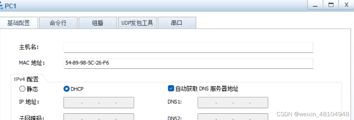
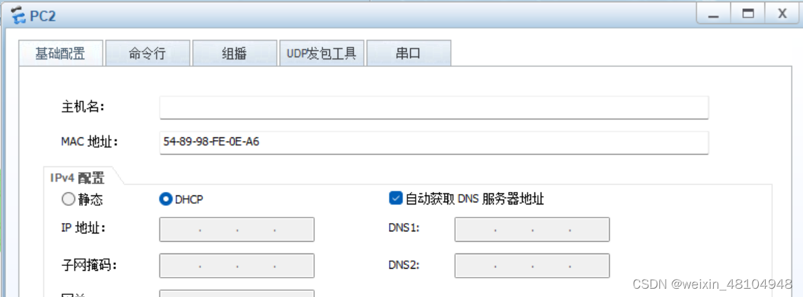
查看是否获取到了IP
PC>ipconfig

Link local IPv6 address...........: fe80::5689:98ff:fe5c:26f6
IPv6 address......................: :: / 128
IPv6 gateway......................: ::
IPv4 address......................: 192.168.1.126
Subnet mask.......................: 255.255.255.224
Gateway...........................: 192.168.1.97
Physical address..................: 54-89-98-5C-26-F6
DNS server........................: 114.114.114.114
                                    8.8.8.8

PC>
PC>ipconfig
Link local IPv6 address...........: fe80::5689:98ff:fefe:ea6
IPv6 address......................: :: / 128
IPv6 gateway......................: ::
IPv4 address......................: 192.168.1.125
Subnet mask.......................: 255.255.255.224
Gateway...........................: 192.168.1.97
Physical address..................: 54-89-98-FE-0E-A6
DNS server........................: 114.114.114.114
8.8.8.8
PC>配置路由
题目要求:用静态,选路最佳,路由表小,不能成环
要路由表小就要想到缺省
先配缺省路由
R5的缺省指向R6

R4的缺省指向R5

R2的缺省指向R4

R1的缺省指向R2和R3

R3的缺省指向R4
先形成一个缺省,这样整个局域网就可以访问到其它网段,也就是互联网,就可以访问到R6后买面无数的地址
<R5>sys
Enter system view, return user view with Ctrl+Z.
[R5]ip rou
[R5]ip route
[R5]ip route-static 0.0.0.0 0 56.1.1.2
[R5]
<R4>sys
Enter system view, return user view with Ctrl+Z.
[R4]ip rou
[R4]ip route
[R4]ip route-static 0.0.0.0 0 192.168.1.18
[R4]ip route-static 0.0.0.0 0 192.168.1.22 preference 61<R3>sys
Enter system view, return user view with Ctrl+Z.
[R3]ip rou
[R3]ip route
[R3]ip route-static 0.0.0.0 0 192.168.1.14
[R3]<R2>sys
Enter system view, return user view with Ctrl+Z.
[R2]ip rou
[R2]ip route
[R2]ip route-static 0.0.0.0 0 192.168.1.10
[R2]<R1>sys
Enter system view, return user view with Ctrl+Z.
[R1]ip rou
[R1]ip route
[R1]ip route-static 0.0.0.0 0 192.168.1.2
[R1]ip route-static 0.0.0.0 0 192.168.1.6
[R1]这样就整个形成了缺省,就可以访问R6以外的网段了,但是缺省路由并不是最佳路由,现在要补上缺省路由不去的路由和缺省路由不是最佳路由的路由
补路由
分析R1

R1配上缺省以后,就可以到右边,但是它的缺省是2个,如果R1 ping R2的环回时,包会从上边走或者从下边绕着走,实际上包走上边是最佳路径,R1到 R2和R4网段同理;所以要给R1在加上2条最佳路由:1,R1到R2的环回;2,R1到R2-R4网段
同理 R1去 R3 和 去R3-R4的这2条路由也要加
一共要给R1加上4条路由
ip route-static 目标地址,目标子网掩码,下一跳。
ip route-static 192.168.1.64 27 192.168.1.2
ip route-static 192.168.1.8 30 192.168.1.2
ip route-static 192.168.1.96 27 192.168.1.6
ip route-static 192.168.1.12 30 192.168.1.6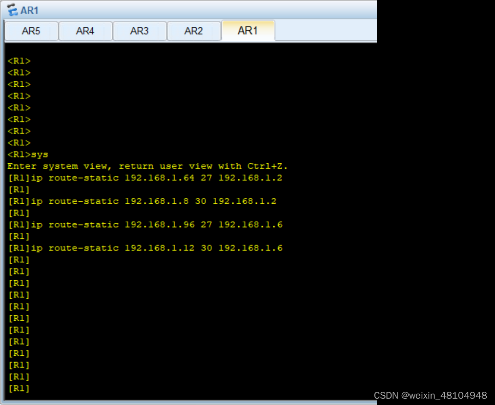
分析R2
R2的缺省的下一跳是R4的 g 0/0/0接口

走缺省,到R4的右边,和到 R3-R4网段是最佳路径

但是 R2 通过缺省  到 R1的环回和 到R1-R3网段 不是最佳路径;到 R3下面的接口 是负载均衡

就要加上
1,R2 到 R1的环回
2,R2 到 R1-R3网段
3,R2 到 R3 的负载均衡--2条


这4条路由

ip route-static 192.168.1.32 27 192.168.1.1
ip route-static 192.168.1.4 30 192.168.1.1
ip route-static 192.168.1.96 27 192.168.1.1
ip route-static 192.168.1.96 27 192.168.1.10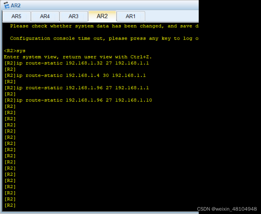
分析R3

还要加
1,3到1环回的路由
2,3到1和2的骨干链路的路由
3,3到2的负载均衡


ip route-static 192.168.1.32 27 192.168.1.5
ip route-static 192.168.1.0 30 192.168.1.5
ip route-static 192.168.1.64 27 192.168.1.5
ip route-static 192.168.1.64 27 192.168.1.14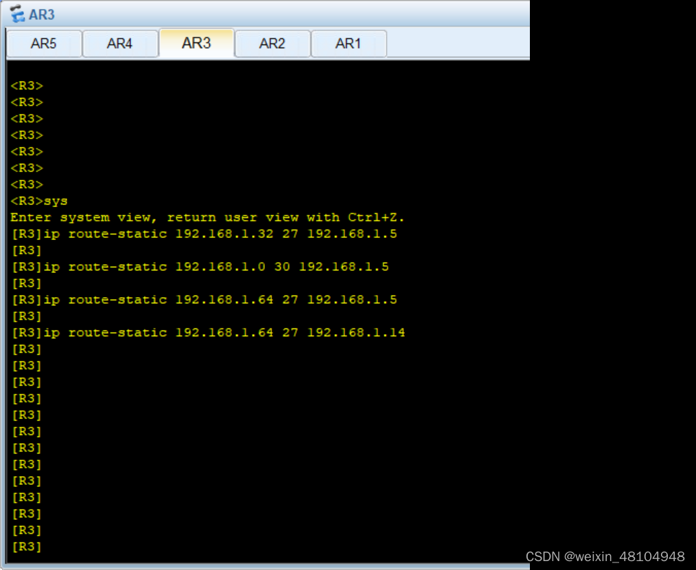
分析R4

R4的缺省是往右的,除了左边和R4直连的2条路,R4到 R2的环回 和到R3的接口 和到 R1-R2, R1-R3,R1的环回都没有路
要加6条路由
ip route-static 192.168.1.64 27 192.168.1.9
ip route-static 192.168.1.0 30 192.168.1.9
ip route-static 192.168.1.96 27 192.168.1.13
ip route-static 192.168.1.4 30 192.168.1.13
ip route-static 192.168.1.32 27 192.168.1.9
ip route-static 192.168.1.32 27 192.168.1.13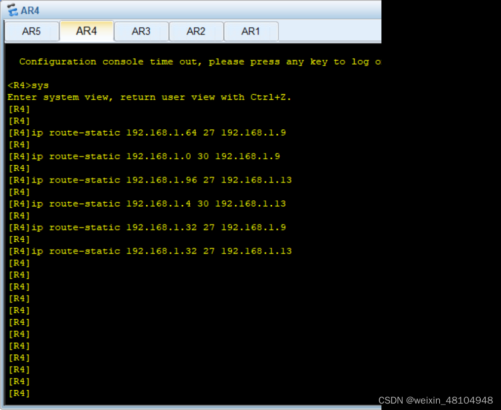
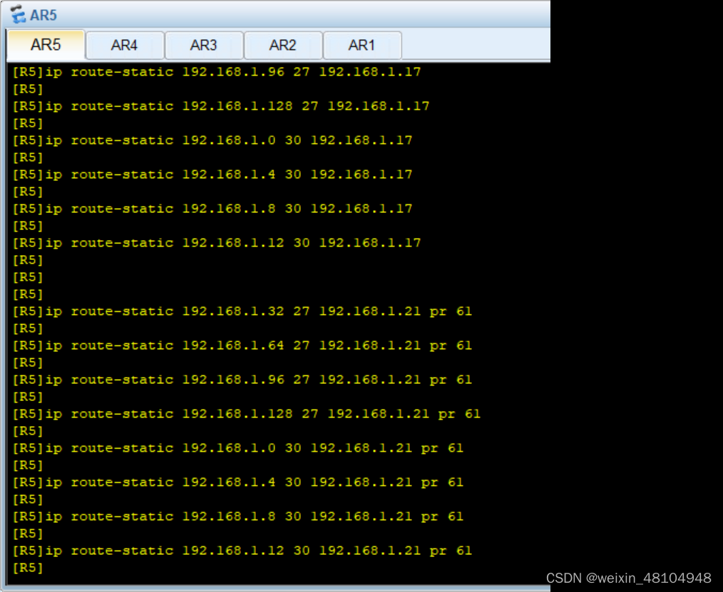
分析R5

R5的环回是到右边的,去左边的的路一条都没有,要加8条路,,再考虑备份链路,一共就是16条链路
要加 到所有环回的路,R3接口,到所有骨干链路的路
ip route-static 192.168.1.32 27 192.168.1.17
ip route-static 192.168.1.64 27 192.168.1.17
ip route-static 192.168.1.96 27 192.168.1.17
ip route-static 192.168.1.128 27 192.168.1.17
ip route-static 192.168.1.0 30 192.168.1.17
ip route-static 192.168.1.4 30 192.168.1.17
ip route-static 192.168.1.8 30 192.168.1.17
ip route-static 192.168.1.12 30 192.168.1.17

ip route-static 192.168.1.32 27 192.168.1.21 pr 61
ip route-static 192.168.1.64 27 192.168.1.21 pr 61
ip route-static 192.168.1.96 27 192.168.1.21 pr 61
ip route-static 192.168.1.128 27 192.168.1.21 pr 61
ip route-static 192.168.1.0 30 192.168.1.21 pr 61
ip route-static 192.168.1.4 30 192.168.1.21 pr 61
ip route-static 192.168.1.8 30 192.168.1.21 pr 61
ip route-static 192.168.1.12 30 192.168.1.21 pr 61
现在整个局域网内都是通的,全网互通,整个R5左边无论是往右还是往左互相ping,都是通的
测试局域网是否通
这里不做演示了
现在真个局域网就算是通了,可以出去,但是回不来,这就需要的是,所有R5左边的,从R5右接口出去,都要变成这个接口的的IP,56.1.1.1
[R5]acl 2000
[R5-acl-basic-2000]rule pe
[R5-acl-basic-2000]rule permit s
[R5-acl-basic-2000]rule permit source 192.168.1.0 0.0.0.255
[R5-acl-basic-2000]q
[R5]int g 0/0/1
[R5-GigabitEthernet0/0/1]nat out
[R5-GigabitEthernet0/0/1]nat outbound 2000
[R5-GigabitEthernet0/0/1]
防环
如果现在R1的这2个环回接口有一个关闭,R2不知道,依然会去找R1,而R1没有这个接口了,此时就会用缺省往回甩,1和2间有缺省,所以有汇总的部分一定要加上空接口
<R1>sys
Enter system view, return user view with Ctrl+Z.
[R1]ip rou
[R1]ip route
[R1]ip route-static 192.168.1.32 27 n
[R1]ip route-static 192.168.1.32 27 NULL 0
[R1]


<R2>sys
Enter system view, return user view with Ctrl+Z.
[R2]ip rou
[R2]ip route
[R2]ip route-static 192.168.1.64 27 n
[R2]ip route-static 192.168.1.64 27 NULL 0
[R2]

<R4>sys
Enter system view, return user view with Ctrl+Z.
[R4]ip rou
[R4]ip route
[R4]ip route-static 192.168.1.128 27 n
[R4]ip route-static 192.168.1.128 27 NULL 0
[R4]
R6 telnet R5 的公有IP时,实际登录到R1上
1,进R1打开telnet服务

2,创建一个账号,账号的作用为telnet

3,在R5上做映射
[R1]aaa
[R1-aaa]loc
[R1-aaa]local-user ppp pr
[R1-aaa]local-user ppp privilege l
[R1-aaa]local-user ppp privilege level 16 pa
[R1-aaa]local-user ppp privilege level 15 pa
[R1-aaa]local-user ppp privilege level 15 password c
[R1-aaa]local-user ppp privilege level 15 password cipher 666666
Info: Add a new user.
[R1-aaa]loc
[R1-aaa]local-user ppp se
[R1-aaa]local-user ppp service-type t
[R1-aaa]local-user ppp service-type telnet
[R1-aaa]q
[R1]user
[R1]user-group
[R1]user-interface
[R1]user-bind
[R1]user-group
[R1]user-interface v
[R1]user-interface vty 0
[R1-ui-vty0]au
[R1-ui-vty0]authentication-mode aaa
[R1-ui-vty0]现在在5上做下映射
<R5>
<R5>sys
Enter system view, return user view with Ctrl+Z.
[R5]int g 0/0/1
[R5-GigabitEthernet0/0/1]nat se
[R5-GigabitEthernet0/0/1]nat server p
[R5-GigabitEthernet0/0/1]nat server protocol t
[R5-GigabitEthernet0/0/1]nat server protocol tcp g
[R5-GigabitEthernet0/0/1]nat server protocol tcp global c
[R5-GigabitEthernet0/0/1]nat server protocol tcp global current-interface in
[R5-GigabitEthernet0/0/1]nat server protocol tcp global current-interface 23 in

[R5-GigabitEthernet0/0/1]nat server protocol tcp global current-interface 23 ins
ide 192.168.1.1 23
Warning:The port 23 is well-known port. If you continue it may cause function fa
ilure.
Are you sure to continue?[Y/N]:y
[R5-GigabitEthernet0/0/1]
The device is running!
<R6>te
<R6>telnet 56.1.1.1
Press CTRL_] to quit telnet mode
Trying 56.1.1.1 ...
Connected to 56.1.1.1 ...
Login authentication
Username:ppp
Password:
-----------------------------------------------------------------------------
User last login information:
-----------------------------------------------------------------------------
Access Type: Telnet
IP-Address : 192.168.1.2
Time : 2022-01-23 17:11:03-08:00
-----------------------------------------------------------------------------
<R1>


 被折叠的 条评论
为什么被折叠?
被折叠的 条评论
为什么被折叠?
 到【灌水乐园】发言


