


 本文详细介绍了如何构建一个具有高冗余性的企业园区网络,采用模块化三层架构,包括接入层、汇聚层和核心层。通过配置VLAN、OSPF和VRRP,确保网络的稳定性和可靠性。具体步骤包括接入层交换机的VLAN划分,汇聚层的链路聚合和网关设置,以及核心层的路由配置,最终实现主备核心路由器的负载均衡和故障切换。
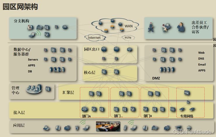
园区网络三层架构
随着企业信息化建设不断深入,企业的生产业务系统、经营管理系统、办公自动化系统均得到大力发展,对于企业园区网的建设要求越来越高。传统园区网建设初期往往面临如下问题:
1、网络架构较为混乱,不便于扩容和维护管理
2、 网络可靠性规划不合理,影响企业生产和经营管理、造成投资浪费
3、网络信息安全存在隐患
4、无法满足日益增长的网络业务需求
5、缺乏简单有效的网络管理系统,企业IT网络运维部门面临很大压力
园区网络结构多趋向于模块化、结构化,接入层按接入人数或者部门划分。
网关多放在汇聚层
接入层
接入层交换机一般部署在楼道的网络机柜中,接入园区网用户(PC机或服务器),提供二层交换机功能,也支持三层接入功能(接入交换机为三层交换机)。
由于接入层交换机直接接园区网用户,根据用户接入信息点数目和类型(GE/FE),对接入交换机的GE/FE接口密度有较高的要求。另外接入交换机部署在楼道网络机柜,数量大,对于成本、功耗和易管理维护等特性要求较高。
汇聚层
园区汇聚层交换机一般部署在楼宇独立的网络汇聚机柜中,汇聚园区接入交换机的流量,一般提供三层交换机功能,汇聚层交换机作为园区网的网关,终结园区网用户的二层流量,进行三层转发。
根据需要,可以在汇聚交换机上集成增值业务板卡(如防火墙,负载均衡器、WLAN AC控制器)或者旁挂独立的增值业务设备,为园区网用户提供增值业务,汇聚交换机需要提供高密度的GE接口,汇聚接入交换机的流量,通过10GE接口接到核心交换。
核心层
园区核心层交换机部署在园区核心机房中,汇聚各楼宇/区域之间的用户流量,提供三层交换机功能,连接园区外部网络到内部用户的“纵向流量”和不同汇聚区域用户之间的“横向流量”要求高密10GE、高转发性能。
出口层
园区出口路由器,连接Internet/WAN广域网和园区内部局域网。
接下来,我们来搭建配置一个园区网络实例,网关在汇聚层,网络高冗余性。
结构拓扑:
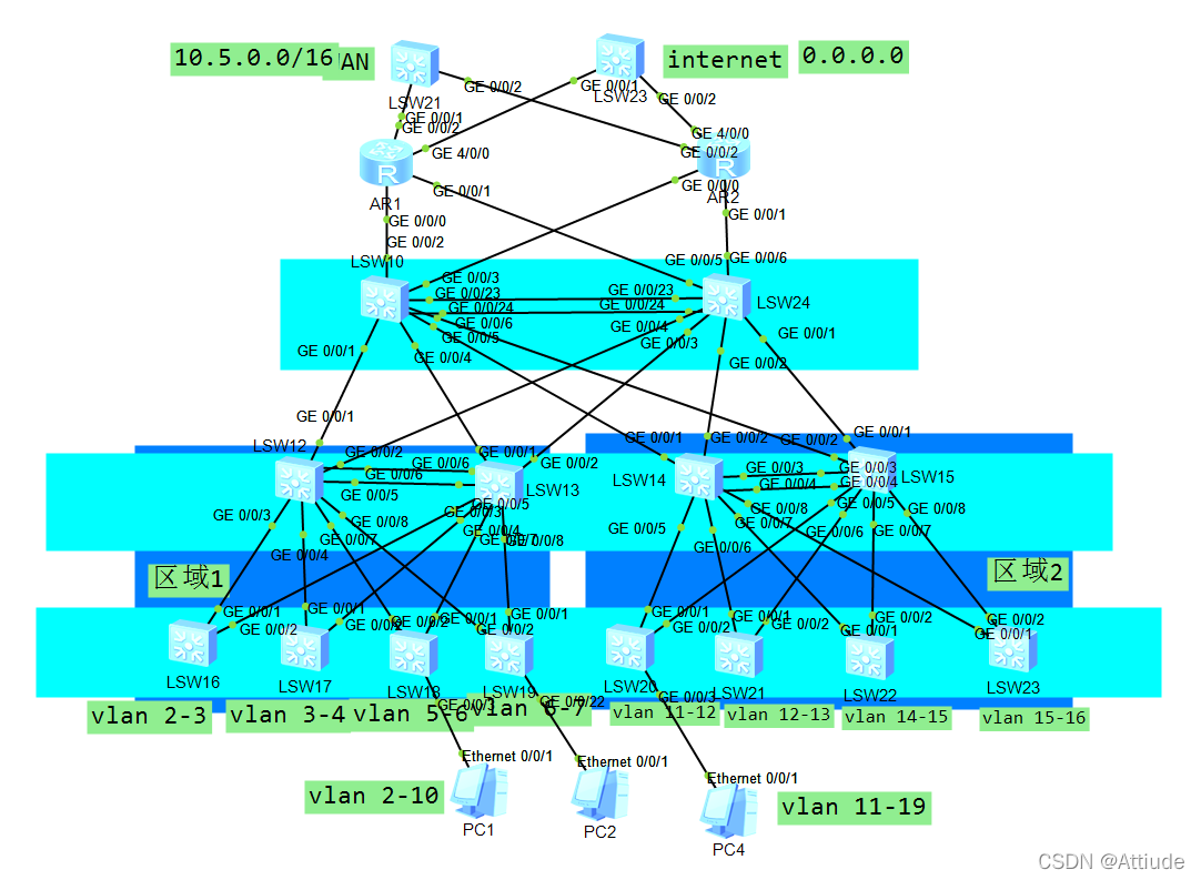
配置思路(以区域2为例):
从接入层开始,先划分vlan
LSW16-LSW19为 vlan 2 - 10 ,LSW20 - LSW23为 vlan 11 - 19,具体vlan划分如图所示。
划分完后,将接入交换机进行逐一配置,把接入层接口划分到vlan中,并配置边缘接口。
vlan batch 11-19  # 以区域二的LSW20为例
port-group group-member g0/0/3 to g0/0/10
	 port link-type access
	 port default vlan 11
 	 stp edged-port enable
port-group group-member g0/0/11 to g0/0/20
	port link-type access
	port default vlan 12
 	stp edged-port enable
port-group group-member g0/0/1 to g0/0/2
 port link-type trunk
 undo port trunk allow-pass vlan 1   #防止环路
 port trunk allow-pass vlan 11 to 12
其余设备根据vlan划分,把自己的接口划分到相对应的vlan中,修改以上的vlan数据即可,此处不作过多赘述。
vlan batch 11-19  # 以区域二的LSW21为例
port-group group-member g0/0/3 to g0/0/10
	 port link-type access
	 port default vlan 12
 	 stp edged-port enable
port-group group-member g0/0/11 to g0/0/20
	port link-type access
	port default vlan 13
 	stp edged-port enable
port-group group-member g0/0/1 to g0/0/2
 port link-type trunk
 undo port trunk allow-pass vlan 1   #防止环路
 port trunk allow-pass vlan 12 to 13
接下来配置二层汇聚层
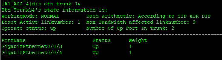
首先把LSW14 和LSW15 两台设备连接做聚合
LSW14:
interface Eth-Trunk34
 port link-type trunk
 undo port trunk allow-pass vlan 1
 port trunk allow-pass vlan 11 to 19
 trunkport GigabitEthernet 0/0/3
 trunkport GigabitEthernet 0/0/4
LSW15:
interface Eth-Trunk34
 port link-type trunk
 undo port trunk allow-pass vlan 1
 port trunk allow-pass vlan 11 to 19 45
 trunkport GigabitEthernet 0/0/3
 trunkport GigabitEthernet 0/0/4
接下来与接入层的设备配置连通
LSW14和LSW15为LSW20-23的负载均衡。
配置如下:
LSW14
interface GigabitEthernet0/0/5
 port link-type trunk
 undo port trunk allow-pass vlan 1
 port trunk allow-pass vlan 11 to 12

interface GigabitEthernet0/0/6
 port link-type trunk
 undo port trunk allow-pass vlan 1
 port trunk allow-pass vlan 12 to 13

interface GigabitEthernet0/0/7
 port link-type trunk
 undo port trunk allow-pass vlan 1
 port trunk allow-pass vlan 14 to 15

interface GigabitEthernet0/0/8
 port link-type trunk
 undo port trunk allow-pass vlan 1
 port trunk allow-pass vlan 15 to 16
LSW15
interface GigabitEthernet0/0/5
 port link-type trunk
 undo port trunk allow-pass vlan 1
 port trunk allow-pass vlan 11 to 12

interface GigabitEthernet0/0/6
 port link-type trunk
 undo port trunk allow-pass vlan 1
 port trunk allow-pass vlan 12 to 13

interface GigabitEthernet0/0/7
 port link-type trunk
 undo port trunk allow-pass vlan 1
 port trunk allow-pass vlan 14 to 15

interface GigabitEthernet0/0/8
 port link-type trunk
 undo port trunk allow-pass vlan 1
 port trunk allow-pass vlan 15 to 16
接下来,配置每个VLAN的网关
LSW14
interface vlan11
 ip address 10.1.3.2 255.255.255.0

interface Vlanif12
 ip address 10.1.12.2 255.255.255.0

interface Vlanif13
 ip address 10.1.13.2 255.255.255.0

interface Vlanif14
 ip address 10.1.14.3 255.255.255.0

interface Vlanif15
 ip address 10.1.15.3 255.255.255.0

interface Vlanif16
 ip address 10.1.16.3 255.255.255.0
LSW15
interface Vlanif11
 ip address 10.1.3.3 255.255.255.0

interface Vlanif12
 ip address 10.1.12.3 255.255.255.0

interface Vlanif13
 ip address 10.1.13.3 255.255.255.0

interface Vlanif14
 ip address 10.1.14.2 255.255.255.0

interface Vlanif15
 ip address 10.1.15.2 255.255.255.0

interface Vlanif16
 ip address 10.1.16.2 255.255.255.0
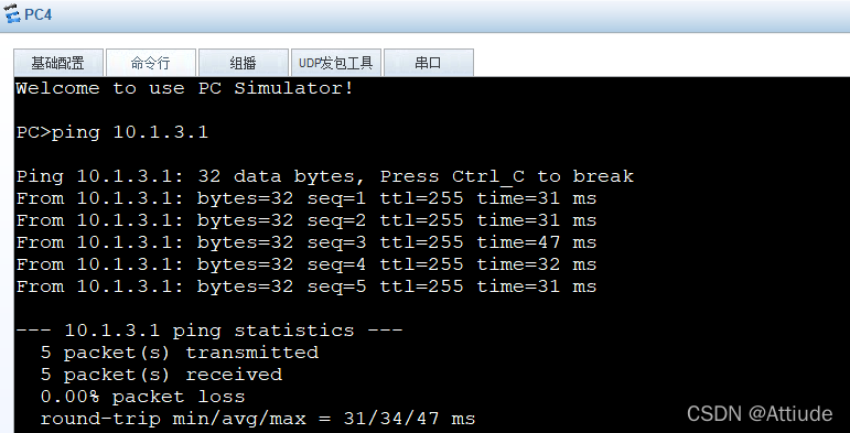
测试用PC4ping网关
接下来,配置汇聚层与核心层部分:
在LSW14上创建vlan 40(LSW24) 和 vlan41(LSW10)
在LSW15上创建vlan 50(LSW24) 和 vlan51(LSW10)
LSW10和LSW24上再创建vlan100
LSW14配置:
vlan batch 40 41
interface GigabitEthernet0/0/1
 port link-type access
 port default vlan 41

interface GigabitEthernet0/0/2
 port link-type access
 port default vlan 40

interface Vlanif41
 ip address 10.0.41.1 255.255.255.0
 interface Vlanif40
 ip address 10.0.40.2 255.255.255.0
LSW15配置:
vlan batch 50 51
interface GigabitEthernet0/0/1
 port link-type access
 port default vlan 50

interface GigabitEthernet0/0/2
 port link-type access
 port default vlan 51

interface Vlanif50
 ip address 10.0.50.1 255.255.255.0
 interface Vlanif51
 ip address 10.0.51.2 255.255.255.0
LSW10配置:
vlan batch 41 51 100
interface Eth-Trunk10
trunkport g0/0/23
trunkport g0/0/24
 port link-type trunk
 port trunk allow-pass vlan 100

interface GigabitEthernet0/0/5
 port link-type access
 port default vlan 41

interface GigabitEthernet0/0/6
 port link-type access
 port default vlan 51

interface Vlanif100
 ip address 10.0.100.1 255.255.255.0

interface Vlanif41
 ip address 10.0.41.1 255.255.255.0

interface Vlanif51
 ip address 10.0.51.1 255.255.255.0
LSW24配置:
vlan batch 40 50 100
interface Eth-Trunk10
trunkport g0/0/23
trunkport g0/0/24
 port link-type trunk
 port trunk allow-pass vlan 100

interface GigabitEthernet0/0/1
 port link-type access
 port default vlan 40

interface GigabitEthernet0/0/2
 port link-type access
 port default vlan 50

interface Vlanif100
 ip address 10.0.100.1 255.255.255.0

interface Vlanif41
 ip address 10.0.40.1 255.255.255.0

interface Vlanif51
 ip address 10.0.50.1 255.255.255.0
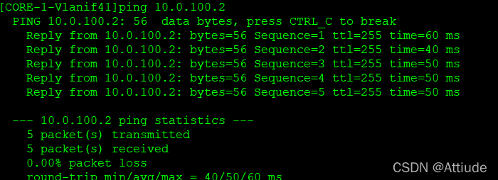
测试用LSW10 ping LSW24:
接下来运行ospf:
我们继续以area2为例:
我们直接在接口运行ospf
LSW10
ospf 2 router-id 7.7.7.7
 area 0.0.0.2

interface Vlanif41
 ospf network-type p2p
 ospf timer hello 1
 ospf enable 2 area 0.0.0.2

interface Vlanif51
 ospf network-type p2p
 ospf timer hello 1
 ospf enable 2 area 0.0.0.2
LSW24
ospf 2 router-id 9.9.9.9
 area 0.0.0.2

interface Vlanif40
 ospf cost 2
 ospf network-type p2p
 ospf timer hello 1
 ospf enable 2 area 0.0.0.2

interface Vlanif50
 ospf cost 2
 ospf network-type p2p
 ospf timer hello 1
 ospf enable 2 area 0.0.0.2
LSW14
ospf 2 router-id 14.14.14.14
 area 0.0.0.2

interface Vlanif41
 ospf cost 2
 ospf network-type p2p
 ospf timer hello 1
 ospf enable 2 area 0.0.0.2

interface Vlanif40
 ospf cost 2
 ospf network-type p2p
 ospf timer hello 1
 ospf enable 2 area 0.0.0.2

interface Vlanif45
 ospf cost 2
 ospf network-type p2p
 ospf timer hello 1
 ospf enable 2 area 0.0.0.2
LSW15
ospf 2 router-id 8.8.8.8
 area 0.0.0.2

interface Vlanif51
 ospf cost 2
 ospf network-type p2p
 ospf timer hello 1
 ospf enable 2 area 0.0.0.2

interface Vlanif50
 ospf cost 2
 ospf network-type p2p
 ospf timer hello 1
 ospf enable 2 area 0.0.0.2

interface Vlanif45
 ospf cost 2
 ospf network-type p2p
 ospf timer hello 1
 ospf enable 2 area 0.0.0.2
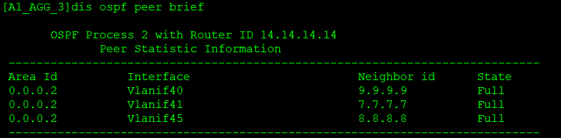
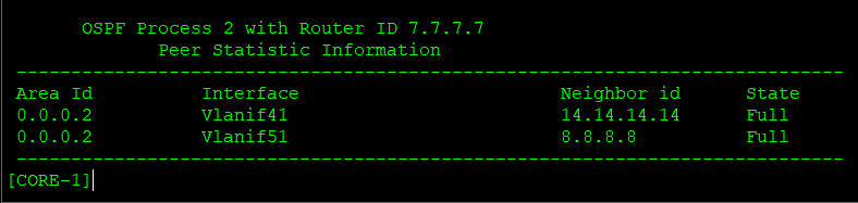
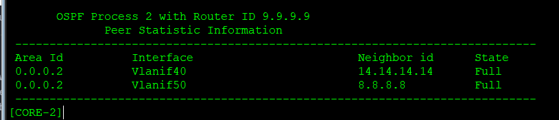
OSPF配置完成后,我们来看邻居建立情况
LSW14
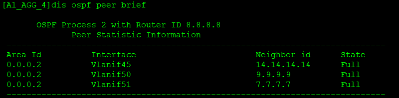
LSW15
LSW10
LSW24
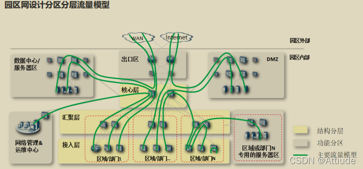
最后,根据流量图设计,我们做以调整
LSW12和 LSW13以LSW10为主核心,以LSW24为备核心
LSW14和 LSW15以LSW24为主核心,以LSW10为备核心
接下来进行配置:
LSW14:
interface vlan11
 vrrp vrid 1 virtual-ip 10.1.3.1
 vrrp vrid 1 priority 120
 vrrp vrid 1 track interface GigabitEthernet0/0/1 reduced 15
 vrrp vrid 1 track interface GigabitEthernet0/0/2 reduced 15
 vrrp vrid 1 authentication-mode md5 123456

interface Vlanif12
 vrrp vrid 1 virtual-ip 10.1.12.1
 vrrp vrid 1 priority 120
 vrrp vrid 1 track interface GigabitEthernet0/0/1 reduced 15
 vrrp vrid 1 track interface GigabitEthernet0/0/2 reduced 15
 vrrp vrid 1 authentication-mode md5 123456

interface vlan13
 vrrp vrid 1 virtual-ip 10.1.13.1
 vrrp vrid 1 priority 120
 vrrp vrid 1 track interface GigabitEthernet0/0/1 reduced 15
 vrrp vrid 1 track interface GigabitEthernet0/0/2 reduced 15
 vrrp vrid 1 authentication-mode md5 123456

interface vlan14
 vrrp vrid 1 virtual-ip 10.1.14.1
 vrrp vrid 1 authentication-mode md5 123456

interface vlan15
 vrrp vrid 1 virtual-ip 10.1.15.1
 vrrp vrid 1 authentication-mode md5 123456

interface vlan16
 vrrp vrid 1 virtual-ip 10.1.16.1
 vrrp vrid 1 authentication-mode md5 123456
LSW15
interface 11
vrrp vrid 1 virtual-ip 10.1.3.1
 vrrp vrid 1 authentication-mode md5 123456

interface 12
 vrrp vrid 1 virtual-ip 10.1.12.1
 vrrp vrid 1 authentication-mode md5 123456

interface 13
 vrrp vrid 1 virtual-ip 10.1.13.1
 vrrp vrid 1 authentication-mode md5 123456

interface 14
 vrrp vrid 1 virtual-ip 10.1.14.1
 vrrp vrid 1 priority 120
 vrrp vrid 1 track interface GigabitEthernet0/0/1 reduced 15
 vrrp vrid 1 track interface GigabitEthernet0/0/2 reduced 15
 vrrp vrid 1 authentication-mode md5 123456

interface 15
 vrrp vrid 1 virtual-ip 10.1.15.1
 vrrp vrid 1 priority 120
 vrrp vrid 1 track interface GigabitEthernet0/0/1 reduced 15
 vrrp vrid 1 track interface GigabitEthernet0/0/2 reduced 15
 vrrp vrid 1 authentication-mode md5 123456

interface 16
 vrrp vrid 1 virtual-ip 10.1.16.1
 vrrp vrid 1 priority 120
 vrrp vrid 1 track interface GigabitEthernet0/0/1 reduced 15
 vrrp vrid 1 track interface GigabitEthernet0/0/2 reduced 15
 vrrp vrid 1 authentication-mode md5 123456


 2042
2042

 被折叠的 条评论
为什么被折叠?
被折叠的 条评论
为什么被折叠?
 到【灌水乐园】发言


