


实验一(远程登录)
1.配置R1的Console登录管理账号和密码(huawei/Admin@123)
[Huawei]sys R1 ##更改名称
[R1]user-interface console 0 ##进入Console口
[R1-ui-console0]authentication-mode aaa ##设置Console的登录模式
[R1-ui-console0]aaa ##进入aaa
[R1-aaa]loc
[R1-aaa]local-user huawei password ?
[R1-aaa]local-user huawei password cipher Admin@123 ##创建用户名密码
Info: Add a new user.
[R1-aaa]local-user admin privilege level 15 ##设置用户优先级
[R1-aaa]local-user admin service-type terminal ##开启登录终端
[R1-aaa]q
[R1]q
<R1>save ##保存
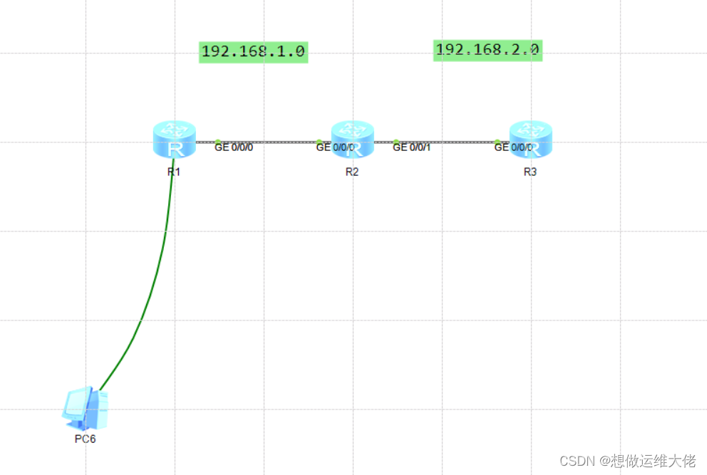
2.R1远程登录管理R2(telnet)
需要在R1,R2,R3上配置IP
R1 G 0 192.168.1.1
R2 G 0 192.168.1.2
R2 G 1 192.168.2.3
R3 G 0 192.168.2.4
[R2]user-interface vty 0 4 ##远程登录用户数量
[R2-ui-vty0-4]authentication-mode password ##远程登录模式
Please configure the login password (maximum length 16):123456
[R2-ui-vty0-4]user privilege level 15 ##远程登录用户优先级
[R2-ui-vty0-4]q

3.R2远程加密登录R3(SSH)
[R3]stelnet server enable
Info: Succeeded in starting the STELNET server.
[R3]user-interface vty 0 4
[R3-ui-vty0-4]authentication-mode aaa
[R3-ui-vty0-4]protocol inbound ssh
[R3-ui-vty0-4]quit
[R3]aaa
[R3-aaa]local-user ssh1 password cipher Admin@123
Info: Add a new user.
[R3-aaa]local-user ssh1 service-type ssh
[R3-aaa]local-user ssh1 privilege level 15
[R3-aaa]
[R3-aaa]
[R3-aaa]rs
[R3-aaa]rsloc
[R3-aaa]rsa
[R3-aaa]q
[R3]rsa local-key-pair create
The key name will be: Host
% RSA keys defined for Host already exist.
Confirm to replace them? (y/n)[n]:y
The range of public key size is (512 ~ 2048).
NOTES: If the key modulus is greater than 512,
It will take a few minutes.
Input the bits in the modulus[default = 512]:
Generating keys...
.................++++++++++++
.....++++++++++++
.++++++++
..++++++++
[R3]ssh user ssh1 authentication-type password
Authentication type setted, and will be in effect next time
[R2]ssh client first-time enable
[R2]stelnet 192.168.2.4
Please input the username:ssh1
Trying 192.168.2.4 ...
Press CTRL+K to abort
Connected to 192.168.2.4 ...
The server is not authenticated. Continue to access it? (y/n)[n]:y
Mar 28 2024 00:20:32-08:00 R2 %%01SSH/4/CONTINUE_KEYEXCHANGE(l)[0]:The server ha
d not been authenticated in the process of exchanging keys. When deciding whethe
r to continue, the user chose Y.
Save the server's public key? (y/n)[n]:y
The server's public key will be saved with the name 192.168.2.4. Please wait...
Mar 28 2024 00:20:35-08:00 R2 %%01SSH/4/SAVE_PUBLICKEY(l)[1]:When deciding wheth
er to save the server's public key 192.168.2.4, the user chose Y.
[R2]
Enter password:
<R3>
实验二 CIDR(无类域间路由汇总)+防环+模拟网段
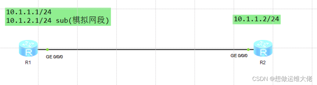
1.sub模拟网段
<Huawei>sys
Enter system view, return user view with Ctrl+Z.
[Huawei]sys R1
[R1]int g 0/0/0
[R1-GigabitEthernet0/0/0]ip address 10.1.1.1 24
[R1-GigabitEthernet0/0/0]ip address 10.1.2.1 24 sub
[R1-GigabitEthernet0/0/0]ping 10.1.1.2
PING 10.1.1.2: 56 data bytes, press CTRL_C to break
Reply from 10.1.1.2: bytes=56 Sequence=1 ttl=255 time=30 ms
Reply from 10.1.1.2: bytes=56 Sequence=2 ttl=255 time=20 ms
Reply from 10.1.1.2: bytes=56 Sequence=3 ttl=255 time=20 ms--- 10.1.1.2 ping statistics ---
3 packet(s) transmitted
3 packet(s) received
0.00% packet loss
round-trip min/avg/max = 20/23/30 ms[R1-GigabitEthernet0/0/0]
<Huawei>sys
Enter system view, return user view with Ctrl+Z.
[Huawei]sys R2
[R2]int g 0/0/0
[R2-GigabitEthernet0/0/0]ip add
[R2-GigabitEthernet0/0/0]ip address 10.1.1.2 24
Apr 1 2024 21:47:51-08:00 R2 %%01IFNET/4/LINK_STATE(l)[0]:The line protocol IP
on the interface GigabitEthernet0/0/0 has entered the UP state.
[R2-GigabitEthernet0/0/0]ping 10.1.1.1
PING 10.1.1.1: 56 data bytes, press CTRL_C to break
Reply from 10.1.1.1: bytes=56 Sequence=1 ttl=255 time=80 ms
Reply from 10.1.1.1: bytes=56 Sequence=2 ttl=255 time=20 ms
Reply from 10.1.1.1: bytes=56 Sequence=3 ttl=255 time=20 ms
Reply from 10.1.1.1: bytes=56 Sequence=4 ttl=255 time=20 ms--- 10.1.1.1 ping statistics ---
4 packet(s) transmitted
4 packet(s) received
0.00% packet loss
round-trip min/avg/max = 20/35/80 ms
[R2-GigabitEthernet0/0/0]ping 10.1.2.1
PING 10.1.2.1: 56 data bytes, press CTRL_C to break
Request time out
Request time out--- 10.1.2.1 ping statistics ---
2 packet(s) transmitted
0 packet(s) received
100.00% packet loss[R2-GigabitEthernet0/0/0]
结论:sub(模拟网段需要配置路由才能访问)
2.CIDR(无类域间路由汇总)
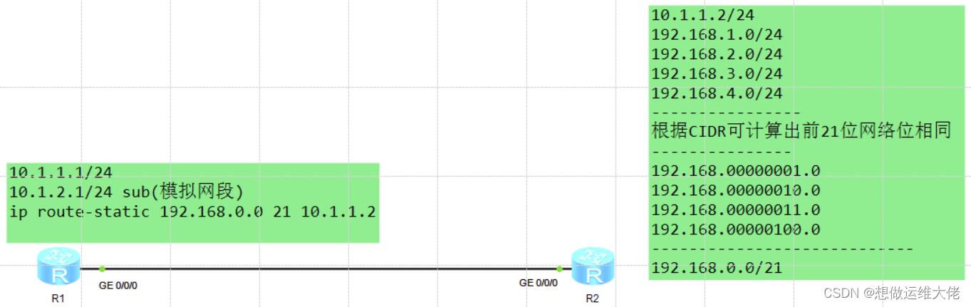
[R2]interface LoopBack 0 ##进入环回接口进行配置
[R2-LoopBack0]ip address 192.168.1.1 24
[R2-LoopBack0]ip address 192.168.2.1 24 sub
[R2-LoopBack0]ip address 192.168.3.1 24 sub
[R2-LoopBack0]ip address 192.168.4.1 24 sub
[R1]ip route-static 192.168.0.0 21 10.1.1.2 ##配置路由
[R1]ping 192.168.1.1
PING 192.168.1.1: 56 data bytes, press CTRL_C to break
Reply from 192.168.1.1: bytes=56 Sequence=1 ttl=255 time=60 ms
Reply from 192.168.1.1: bytes=56 Sequence=2 ttl=255 time=10 ms
Reply from 192.168.1.1: bytes=56 Sequence=3 ttl=255 time=30 ms--- 192.168.1.1 ping statistics ---
3 packet(s) transmitted
3 packet(s) received
0.00% packet loss
round-trip min/avg/max = 10/33/60 ms[R1]ping 192.168.2.1
PING 192.168.2.1: 56 data bytes, press CTRL_C to break
Reply from 192.168.2.1: bytes=56 Sequence=1 ttl=255 time=20 ms
Reply from 192.168.2.1: bytes=56 Sequence=2 ttl=255 time=20 ms
Reply from 192.168.2.1: bytes=56 Sequence=3 ttl=255 time=20 ms
Reply from 192.168.2.1: bytes=56 Sequence=4 ttl=255 time=20 ms--- 192.168.2.1 ping statistics ---
4 packet(s) transmitted
4 packet(s) received
0.00% packet loss
round-trip min/avg/max = 20/20/20 ms
3.防环

[R2]ip route-static 0.0.0.0 0 10.1.1.1
[R1]tracert 192.168.5.1
traceroute to 192.168.5.1(192.168.5.1), max hops: 30 ,packet length: 40,press
CTRL_C to break1 10.1.1.2 20 ms 10 ms 10 ms
2 10.1.1.1 10 ms 20 ms 10 ms
3 10.1.1.2 20 ms 20 ms 20 ms
4 10.1.1.1 20 ms 20 ms 10 ms
5 10.1.1.2 20 ms 30 ms 30 ms
6 10.1.1.1 20 ms 20 ms 20 ms
7 10.1.1.2 30 ms 40 ms 30 ms
8 10.1.1.1 20 ms 20 ms 30 ms
 配置一条黑洞接口
[R1]tracert 192.168.5.1
traceroute to 192.168.5.1(192.168.5.1), max hops: 30 ,packet length: 40,press
CTRL_C to break1 * * *
2 * * *
3 * * *
4 * * *
5 *
实验三 静态路由配置(全网可达)

R1配置
<Huawei>sys
Enter system view, return user view with Ctrl+Z.
[Huawei]SYS R1
[R1]int g 0/0/1
[R1-GigabitEthernet0/0/1]ip add
[R1-GigabitEthernet0/0/1]ip address 12.1.1.2 24
Apr 7 2024 04:40:10-08:00 R1 %%01IFNET/4/LINK_STATE(l)[2]:The line protocol IP
on the interface GigabitEthernet0/0/1 has entered the UP state.
[R1-GigabitEthernet0/0/1]int g 0/0/0
[R1-GigabitEthernet0/0/0]ip address 12.1.1.1 24
Apr 7 2024 04:44:05-08:00 R1 %%01IFNET/4/LINK_STATE(l)[4]:The line protocol IP
on the interface GigabitEthernet0/0/0 has entered the UP state.
[R1-GigabitEthernet0/0/0]int g 0/0/1
[R1-GigabitEthernet0/0/1]ip address 10.1.1.2 24
[R1]ip route-static 10.1.2.0 24 12.1.1.2
[R1]ip route-static 23.1.1.0 24 12.1.1.2
[R1]ip route-static 34.1.1.0 24 12.1.1.2
R2配置
<Huawei>sys
Enter system view, return user view with Ctrl+Z.
[Huawei]sys R2
[R2]int g 0/0/0
[R2-GigabitEthernet0/0/0]ip add
[R2-GigabitEthernet0/0/0]ip address 12.1.1.2 24
Apr 7 2024 04:45:52-08:00 R2 %%01IFNET/4/LINK_STATE(l)[2]:The line protocol IP
on the interface GigabitEthernet0/0/0 has entered the UP state.
[R2-GigabitEthernet0/0/0]int g 0/0/1
[R2-GigabitEthernet0/0/1]ip address 23.1.1.2 24
Apr 7 2024 04:46:33-08:00 R2 %%01IFNET/4/LINK_STATE(l)[3]:The line protocol IP
on the interface GigabitEthernet0/0/1 has entered the UP state.
[R2-GigabitEthernet0/0/1]
[R2]ip route-static 10.1.2.0 24 23.1.1.3
[R2]ip route-static 10.1.1.0 24 12.1.1.1
[R2]ip route-static 34.1.1.10 24 23.1.1.3
R3配置
<Huawei> sys
Enter system view, return user view with Ctrl+Z.
[Huawei]sys R3
[R3]int g 0/0/0
[R3-GigabitEthernet0/0/0]ip add
[R3-GigabitEthernet0/0/0]ip address 23.1.1.3 24
Apr 7 2024 04:47:17-08:00 R3 %%01IFNET/4/LINK_STATE(l)[1]:The line protocol IP
on the interface GigabitEthernet0/0/0 has entered the UP state.
[R3-GigabitEthernet0/0/0]int g 0/0/1
[R3-GigabitEthernet0/0/1]ip add
[R3-GigabitEthernet0/0/1]ip address 34.1.1.3 24
Apr 7 2024 04:47:57-08:00 R3 %%01IFNET/4/LINK_STATE(l)[2]:The line protocol IP
on the interface GigabitEthernet0/0/1 has entered the UP state.
[R3]ip route-static 10.1.1.0 24 23.1.1.2
[R3]ip route-static 10.1.2.0 24 34.1.1.4
[R3]ip route-static 12.1.1.0 24 23.1.1.2
R4配置
<Huawei>sys
Enter system view, return user view with Ctrl+Z.
[Huawei]sys R4
[R4]int g 0/0/0
[R4-GigabitEthernet0/0/0]ip add 34.1.1.4 24
Apr 7 2024 04:48:51-08:00 R4 %%01IFNET/4/LINK_STATE(l)[2]:The line protocol IP
on the interface GigabitEthernet0/0/0 has entered the UP state.
[R4-GigabitEthernet0/0/0]int g 0/0/1
[R4-GigabitEthernet0/0/1]ip address 10.1.2.2 24
Apr 7 2024 04:50:04-08:00 R4 %%01IFNET/4/LINK_STATE(l)[3]:The line protocol IP
on the interface GigabitEthernet0/0/1 has entered the UP state.
[R4]ip route-static 10.1.1.0 24 34.1.1.3
[R4]ip route-static 12.1.1.0 24 34.1.1.3
[R4]ip route-static 23.1.1.0 24 34.1.1.3
实验四 单臂路由(Hybird配置)

<Huawei>sys
Enter system view, return user view with Ctrl+Z.
[Huawei]sys SW1
[SW1]vlan batch
[SW1]vlan batch 10 20
Info: This operation may take a few seconds. Please wait for a moment...done.
[SW1-Ethernet0/0/1]port hybrid pvid vlan 10
[SW1-Ethernet0/0/1]port hybrid
[SW1-port-group-hybrid]port hybrid untagged vlan 10
Error: Unrecognized command found at '^' position.
[SW1-port-group-hybrid]q
[SW1]int e 0/0/3
[SW1-Ethernet0/0/3]port hybrid tagged vlan 10 20
[SW1-Ethernet0/0/3]int e 0/0/2
[SW1-Ethernet0/0/2]port hybrid pvid vlan 20
[SW1-Ethernet0/0/2]port hybrid untagged vlan 20
<Huawei>sys
Enter system view, return user view with Ctrl+Z.
[Huawei]sys R1
[R1]int GigabitEthernet 0/0/0.10
[R1-GigabitEthernet0/0/0.10]dot1q termination vid 10
[R1-GigabitEthernet0/0/0.10]ip address 192.168.10.254 24
[R1-GigabitEthernet0/0/0.10]arp broadcast enable
[R1-GigabitEthernet0/0/0.10]display this
[V200R003C00]
#
interface GigabitEthernet0/0/0.10
dot1q termination vid 10
ip address 192.168.10.254 255.255.255.0
arp broadcast enable
#
return
[R1]int g 0/0/0.20
[R1-GigabitEthernet0/0/0.20]dot1q termination vid 20
[R1-GigabitEthernet0/0/0.20]ip address 192.168.20.254 24
[R1-GigabitEthernet0/0/0.20]arp broadcast enable
[R1-GigabitEthernet0/0/0.20]display this
[V200R003C00]
#
interface GigabitEthernet0/0/0.20
dot1q termination vid 20
ip address 192.168.20.254 255.255.255.0
arp broadcast enable
#
return
[R1]dis arp all
IP ADDRESS MAC ADDRESS EXPIRE(M) TYPE INTERFACE VPN-INSTANCE
VLAN/CEVLAN PVC
------------------------------------------------------------------------------
192.168.10.254 00e0-fc27-175f I - GE0/0/0.10
192.168.20.254 00e0-fc27-175f I - GE0/0/0.20
------------------------------------------------------------------------------
Total:2 Dynamic:0 Static:0 Interface:2
[R1]dis
[R1]display ar
[R1]display arp all
IP ADDRESS MAC ADDRESS EXPIRE(M) TYPE INTERFACE VPN-INSTANCE
VLAN/CEVLAN PVC
------------------------------------------------------------------------------
192.168.10.254 00e0-fc27-175f I - GE0/0/0.10
192.168.10.1 5489-98d4-4e9d 20 D-0 GE0/0/0.10
10/-
192.168.20.254 00e0-fc27-175f I - GE0/0/0.20
192.168.20.1 5489-9839-6d3b 20 D-0 GE0/0/0.20
20/-
------------------------------------------------------------------------------
Total:4 Dynamic:2 Static:0 Interface:2
##通过pc1 ping pc2触发 arp关系表构建映射
实验五 ACL流量访问控制+通配符应用

R1配置
<Huawei>sys
[Huawei]sys R1
[R1]int g 0/0/0
[R1-GigabitEthernet0/0/0]ip address 12.1.1.1 24
[R1-GigabitEthernet0/0/0]ospf 1
[R1-ospf-1]area 0
[R1-ospf-1-area-0.0.0.0]network 12.1.1.0 255.255.255.0
[R1]interface LoopBack 0
[R1-LoopBack0]ip address 192.168.2.1 32
[R1-LoopBack0]ospf enable 1 area 0
R2配置
<Huawei>sys
[Huawei]sys R2
[R2]int g 0/0/0
[R2-GigabitEthernet0/0/0]ip address 12.1.1.2 24
[R2-GigabitEthernet0/0/0]int g 0/0/1
[R2-GigabitEthernet0/0/1]ip address 23.1.1.2 24
[R2-GigabitEthernet0/0/1]ospf 1
[R2-ospf-1]area 0
[R2-ospf-1-area-0.0.0.0]network 12.1.1.0 255.255.255.0
[R2-ospf-1-area-0.0.0.0]network 23.1.1.0 255.255.255.0
[R2]acl 2000
[R2-acl-basic-2000]rule deny source 192.168.1.1 0.0.0.6
[R2-acl-basic-2000]q
[R2]int g 0/0/1
[R2-GigabitEthernet0/0/1]traffic-filter inbound acl 2000
R3配置
<Huawei>sys
[Huawei]sys R3
[R3]int GigabitEthernet 0/0/0
[R3-GigabitEthernet0/0/0]ip address 23.1.1.3 24
[R3-GigabitEthernet0/0/0]q
[R3]interface LoopBack 0
[R3-LoopBack0]ip address 192.168.1.0 32
[R3-LoopBack0]ip address 192.168.1.1 32 sub
[R3-LoopBack0]ip address 192.168.1.2 32 sub
[R3-LoopBack0]ip address 192.168.1.3 32 sub
[R3-LoopBack0]ip address 192.168.1.4 32 sub
[R3-LoopBack0]ip address 192.168.1.5 32 sub
[R3-LoopBack0]ip address 192.168.1.6 32 sub
[R3-LoopBack0]ip address 192.168.1.7 32 sub
[R3-LoopBack0]q
[R3]ospf 1
[R3-ospf-1]area 0
[R3-ospf-1-area-0.0.0.0]network 23.1.1.0 255.255.255.0
[R3]int LoopBack 0
[R3-LoopBack0]ospf enable 1 area 0
验证:
[R1-LoopBack0]ping 192.168.1.1
PING 192.168.1.1: 56 data bytes, press CTRL_C to break
Request time out
Request time out
Request time out
Request time out
Request time out--- 192.168.1.1 ping statistics ---
5 packet(s) transmitted
0 packet(s) received
100.00% packet loss[R1-LoopBack0]ping 192.168.1.0
PING 192.168.1.0: 56 data bytes, press CTRL_C to break
Reply from 192.168.1.0: bytes=56 Sequence=1 ttl=254 time=30 ms
Reply from 192.168.1.0: bytes=56 Sequence=2 ttl=254 time=20 ms
Reply from 192.168.1.0: bytes=56 Sequence=3 ttl=254 time=30 ms
Reply from 192.168.1.0: bytes=56 Sequence=4 ttl=254 time=20 ms
Reply from 192.168.1.0: bytes=56 Sequence=5 ttl=254 time=20 ms--- 192.168.1.0 ping statistics ---
5 packet(s) transmitted
5 packet(s) received
0.00% packet loss
round-trip min/avg/max = 20/24/30 ms


 1716
1716


 被折叠的 条评论
为什么被折叠?
被折叠的 条评论
为什么被折叠?
 到【灌水乐园】发言


