


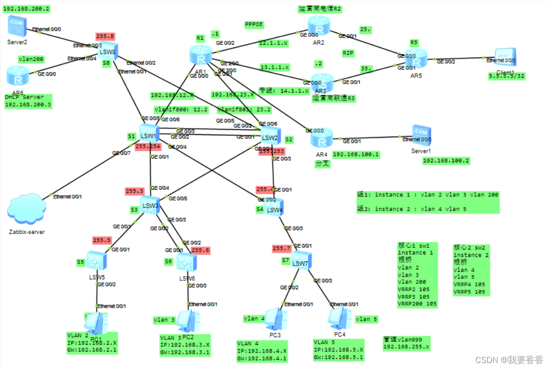
该拓扑架构是我部署zabbix用来做测试的网络拓扑,涉及到DHCP,VLAN,链路聚合,MSTP+VRRP,路由,BFD,NAT,ISP,ACL,分支机构,WEB服务器等;配置完成后可通过接入zabbix进行网络监控,下文会讲解如何通过zabbix监控网络拓扑;
实验配置:
接入交换机链路配置:
[S5]配置:
vlan batch 2 to 5 200 999
#
interface GigabitEthernet0/0/1
 port link-type trunk
 port trunk allow-pass vlan 2 999
#
interface GigabitEthernet0/0/2
 port link-type access
 port default vlan 2
----------------------------------

[S6]配置:
vlan batch 2 to 5 200 999
#
interface Eth-Trunk1
 mode lacp-static
 trunkport GigabitEthernet 0/0/1
 trunkport GigabitEthernet 0/0/2
 port link-type trunk
 port trunk allow-pass vlan 3 999
#
interface GigabitEthernet0/0/3
 port link-type access
 port default vlan 3
---------------------------------
[S7]配置:
vlan batch 2 to 5 200 999
#
interface GigabitEthernet0/0/1
 port link-type trunk
 port trunk allow-pass vlan 4 to 5 999
#
interface GigabitEthernet0/0/2
 port link-type access
 port default vlan 4
#
interface GigabitEthernet0/0/3
 port link-type access
 port default vlan 5
---------------------------------

[s8]配置:
vlan batch 2 to 5 200 999
#
interface Ethernet0/0/1
 port link-type trunk
 port trunk allow-pass vlan 200 999
#
interface Ethernet0/0/2
 port link-type trunk
 port trunk allow-pass vlan 200 999
#
interface Ethernet0/0/3
 port link-type access
 port default vlan 200
#
interface Ethernet0/0/4
 port link-type access
 port default vlan 200
汇聚交换机链路配置:
[S3]配置:
vlan batch 2 to 5 200 999
#
interface Eth-Trunk1
 mode lacp-static
 trunkport GigabitEthernet 0/0/2
 trunkport GigabitEthernet 0/0/3
 port link-type trunk
 port trunk allow-pass vlan 3 999
#
interface GigabitEthernet0/0/1
 port link-type trunk
 port trunk allow-pass vlan 2 999
#
interface GigabitEthernet0/0/4
 port link-type trunk
 port trunk allow-pass vlan 2 to 3 999
#
interface GigabitEthernet0/0/5
 port link-type trunk
 port trunk allow-pass vlan 2 to 3 999
---------------------------------------

[S4]配置:
vlan batch 2 to 5 200 999
#
interface GigabitEthernet0/0/1
 port link-type trunk
 port trunk allow-pass vlan 4 to 5 999
#
interface GigabitEthernet0/0/2
 port link-type trunk
 port trunk allow-pass vlan 4 to 5 999
#
interface GigabitEthernet0/0/3
 port link-type trunk
 port trunk allow-pass vlan 4 to 5 999
核心交换机链路配置:
[S1]配置:
vlan batch 2 to 5 88 200 800 999
#
interface Eth-Trunk2
 trunkport GigabitEthernet 0/0/2
 trunkport GigabitEthernet 0/0/3
 mode lacp-static
 port link-type trunk
 port trunk allow-pass vlan 2 to 5 200 999
#
interface GigabitEthernet0/0/1
 port link-type trunk
 port trunk allow-pass vlan 2 to 3 999
#
interface GigabitEthernet0/0/4
 port link-type trunk
 port trunk allow-pass vlan 4 to 5 999
#
interface GigabitEthernet0/0/5
 port link-type trunk
 port trunk allow-pass vlan 200 999
----------------------------------------------

[S2]配置:
vlan batch 2 to 5 88 200 800 999
#
interface Eth-Trunk2
 trunkport GigabitEthernet 0/0/1
 trunkport GigabitEthernet 0/0/2
 mode lacp-static
 port link-type trunk
 port trunk allow-pass vlan 2 to 5 200 999
#
interface GigabitEthernet0/0/3
 port link-type trunk
 port trunk allow-pass vlan 4 to 5 999
#
interface GigabitEthernet0/0/4
 port link-type trunk
 port trunk allow-pass vlan 2 to 3 999
#
interface GigabitEthernet0/0/5
 port link-type trunk
 port trunk allow-pass vlan 200 999
阶段小结:
接入交换机配置所属区域vlan,与pc端配access,与交换机端配trunk;配链路捆绑,模式lacp;
汇聚交换机配所有vlan,与接入交换机配trunk,配链路捆绑,模式lacp,与核心交换机配trunk,仅允许所在区域vlan通过;
核心交换机配链路捆绑,模式lacp,允许所有vlan通过;
即s3通往核心仅vlan 2 3 999
s4通往核心仅vlan 4 5 999
s8通往核心仅vlan 200 999
s1和s2之间vlan2 to 5 200 999
MSTP配置:(所有汇聚核心交换机都要配置)
#所有汇聚核心交换机配置,实现流量负载分担
stp region-configuration
 region-name aa
 revision-level 1
 instance 1 vlan 2 to 3 200
 instance 2 vlan 4 to 5
 active region-configuration
-------------------------------------
[S1]stp instance 1 root primary
[S1]stp instance 2 root secondary

[S2]stp instance 2 root primary
[S2]stp instance 1 root secondary
VRRP配置:
[S1]配置:
interface Vlanif2
 ip address 192.168.2.254 255.255.255.0
 vrrp vrid 2 virtual-ip 192.168.2.1
 vrrp vrid 2 priority 105
#
interface Vlanif3
 ip address 192.168.3.254 255.255.255.0
 vrrp vrid 3 virtual-ip 192.168.3.1
 vrrp vrid 3 priority 105
#
interface Vlanif4
 ip address 192.168.4.254 255.255.255.0
 vrrp vrid 4 virtual-ip 192.168.4.1
#
interface Vlanif5
 ip address 192.168.5.254 255.255.255.0
 vrrp vrid 5 virtual-ip 192.168.5.1
#
interface Vlanif200
 ip address 192.168.200.254 255.255.255.0
 vrrp vrid 200 virtual-ip 192.168.200.1
 vrrp vrid 200 priority 105

-----------------------------------------
[S2]配置:
interface Vlanif2
 ip address 192.168.2.253 255.255.255.0
 vrrp vrid 2 virtual-ip 192.168.2.1
#
interface Vlanif3
 ip address 192.168.3.253 255.255.255.0
 vrrp vrid 3 virtual-ip 192.168.3.1
#
interface Vlanif4
 ip address 192.168.4.253 255.255.255.0
 vrrp vrid 4 virtual-ip 192.168.4.1
 vrrp vrid 4 priority 105
#
interface Vlanif5
 ip address 192.168.5.253 255.255.255.0
 vrrp vrid 5 virtual-ip 192.168.5.1
 vrrp vrid 5 priority 105
#
interface Vlanif200
 ip address 192.168.200.253 255.255.255.0
 vrrp vrid 200 virtual-ip 192.168.200.1
BFD配置:使用vrrp track bfd
#实现核心交换机和出口路由器的bfd功能
#检测隐藏假死的状态

#注意先将接口ip配置再配置BFD


[R1]配置:
interface GigabitEthernet0/0/0
 ip address 192.168.12.1 255.255.255.0
#
interface GigabitEthernet0/0/1
 ip address 192.168.23.1 255.255.255.0
#
bfd bb bind peer-ip 192.168.12.2 source-ip 192.168.12.1 auto
 commit
#
bfd cc bind peer-ip 192.168.23.2 source-ip 192.168.23.1 auto
 commit
#
-----------------------------------------------------------
#此时vrrp不仅要track上面的口,底下的接口也要track到
#因为如果底下接口不track,如果它down了,心跳是正常的不能切换
#所有要track接口跟踪

[S1]配置:
interface Vlanif800
 ip address 192.168.12.2 255.255.255.0
#
interface GigabitEthernet0/0/6
 port link-type access
 port default vlan 800
#
bfd bb bind peer-ip 192.168.12.1 source-ip 192.168.12.2 auto
 commit
#
int vlanif 2
 vrrp vrid 2 track bfd-session session-name bb
 vrrp vrid 2 track interface GigabitEthernet0/0/1
#
int vlanif 3
 vrrp vrid 3 track bfd-session session-name bb
 vrrp vrid 3 track interface GigabitEthernet0/0/1
#
int vlanif 200
 vrrp vrid 200 track bfd-session session-name bb
 vrrp vrid 200 track interface GigabitEthernet0/0/1
-----------------------------------------------------------
[S2]配置:
interface Vlanif801
 ip address 192.168.23.2 255.255.255.0
#
interface GigabitEthernet0/0/6
 port link-type access
 port default vlan 801
#
bfd cc bind peer-ip 192.168.23.1 source-ip 192.168.23.2 auto
 commit
#
interface Vlanif4
 vrrp vrid 4 track interface GigabitEthernet0/0/3
 vrrp vrid 4 track bfd-session session-name cc
#
interface Vlanif5
 vrrp vrid 5 track interface GigabitEthernet0/0/3
 vrrp vrid 5 track bfd-session session-name cc
配置ospf:R1,S1,S2,R4运行ospf,宣告网络,建立邻居
[S1]配置:
ospf 1
 area 0.0.0.0
  network 192.168.12.0 0.0.0.255
  network 192.168.2.0 0.0.0.255
  network 192.168.3.0 0.0.0.255
  network 192.168.4.0 0.0.0.255
  network 192.168.5.0 0.0.0.255
  network 192.168.200.0 0.0.0.255

[S2]配置:
ospf 1
 area 0.0.0.0
  network 192.168.23.0 0.0.0.255
  network 192.168.2.0 0.0.0.255
  network 192.168.3.0 0.0.0.255
  network 192.168.4.0 0.0.0.255
  network 192.168.5.0 0.0.0.255
  network 192.168.200.0 0.0.0.255

[R1]配置:
interface GigabitEthernet3/0/0
 ip address 14.1.1.1 255.255.255.0
#
ospf 1
 area 0.0.0.0
  network 14.1.1.0 0.0.0.255
  network 192.168.12.0 0.0.0.255
  network 192.168.23.0 0.0.0.255

[R4]配置:
interface GigabitEthernet0/0/0
 ip address 14.1.1.2 255.255.255.0
#
interface GigabitEthernet0/0/1
 ip address 192.168.100.1 255.255.255.0
#
ospf 1
 area 0.0.0.0
  network 14.1.1.0 0.0.0.255
  network 192.168.100.0 0.0.0.255
R2,R3,R5 rip(模拟运营商网络) 配置:
[R2]配置:
rip 1
version 2
network 12.0.0.0
network 25.0.0.0
[R3]配置:
rip 1
version 2
network 13.0.0.0
network 35.0.0.0
[R5]配置:
rip 1
version 2
network 25.0.0.0
network 35.0.0.0
出口路由器配置NAT:
#配置静态路由,指向R1
[S1]ip route-static 0.0.0.0 0 192.168.12.1
[S1]ip route-static 0.0.0.0 0 192.168.23.1 preference 65
[S2]ip route-static 0.0.0.0 0 192.168.23.1
[S2]ip route-static 0.0.0.0 0 192.168.12.1 preference 65

#配置ACL,端口转换
[R1]ip route-static 0.0.0.0 0 13.1.1.2
[R1]acl 2000
[R1-acl-basic-2000]rule permit source 192.168.0.0 0.0.255.255
[R1-acl-basic-2000]int g2/0/0
[R1-GigabitEthernet2/0/0]nat outbound 2000


#ospf cost值调整,确保来回路径一致:
#否则会不满足防火墙安全策略,回包是基于会话来回包的,即在S1,S2上进入vlan改ospf开销值;
[S1]int vlanif 4
[S1-Vlanif4]ospf cost 4
[S1-Vlanif4]int vlanif 5
[S1-Vlanif5]ospf cost 4

[S2]int vlanif 2
[S2-Vlanif2]ospf cost 4
[S2-Vlanif2]int vlanif 3
[S2-Vlanif3]ospf cost 4
[S2-Vlanif3]int vlan 200
[S2-Vlanif200]ospf cost 4
DHCP配置 :
#冗余型网络拓扑分配地址可以用核心交换机也可以用dhcp服务器;
#如果用核心交换机分配地址要注意地址重复性(如果地址池范围相同可能分配重复);
#为保持地址唯一性,两个核心交换机地址池范围应不同;
#用户数量多可用服务器分配,减少服务器压力,若一台核心挂了或链路故障依然能够分配ip地址;

DHCP服务器配置:

dhcp enable
#
ip pool vlan2
 gateway-list 192.168.2.1
 network 192.168.2.0 mask 255.255.255.0
 excluded-ip-address 192.168.2.249 192.168.2.254   #去除部分地址,避免分配重复
 dns-list 114.114.114.114 8.8.8.8
#
ip pool vlan3
 gateway-list 192.168.3.1
 network 192.168.3.0 mask 255.255.255.0
 excluded-ip-address 192.168.3.249 192.168.3.254
 dns-list 114.114.114.114 8.8.8.8
#
ip pool vlan4
 gateway-list 192.168.4.1
 network 192.168.4.0 mask 255.255.255.0
 excluded-ip-address 192.168.4.249 192.168.4.254
 dns-list 114.114.114.114 8.8.8.8
#
ip pool vlan5
 gateway-list 192.168.5.1
 network 192.168.5.0 mask 255.255.255.0
 excluded-ip-address 192.168.5.249 192.168.5.254
 dns-list 114.114.114.114 8.8.8.8
#
interface GigabitEthernet0/0/0
 ip address 192.168.200.3 255.255.255.0
 dhcp select global
#
ip route-static 0.0.0.0 0.0.0.0 192.168.200.1
--------------------------------------------------------------------------

#此时三层设备将dhcp的广播隔离了,应使用dhcp中继技术,在S1,S2上配置dhcp中继,配置内容相同
dhcp enable
#
int vlanif 2
 dhcp select relay
 dhcp relay server-ip 192.168.200.3
#
int vlanif 3
 dhcp select relay
 dhcp relay server-ip 192.168.200.3
#
int vlanif 4
 dhcp select relay
 dhcp relay server-ip 192.168.200.3
#
int vlanif 5
 dhcp select relay
 dhcp relay server-ip 192.168.200.3
--------------------------------------------------------------------------
#如果不去除部分地址,pc端虽获取到地址但是不能用,华为dhcp分配地址默认从254开始分配,
#此时网络中已有.254,.253,应更改地址池;可留几个地址做静态分配,
#即剔除地址池中几个地址,因为不剔除的话dhcp不知道地址已被分配则会造成地址冲突,
#即保留部分地址不分配;

#此时再在pc端选择dhcp, 命令端ipconfig /renew即可,
PPPOE配置:
拨号上网,家用用户选择,带宽稳定性不如企业光纤通信;实际工作中可通过web界面配置
客户端R1配置:
acl number 2001
 rule 5 permit source 192.168.0.0 0.0.255.255
#
interface Dialer1
 link-protocol ppp
 ppp pap local-user 0513 password simple 123456
 mtu 1492
 ip address ppp-negotiate
 dialer user 0513
 dialer bundle 2
 nat outbound 2001
#
int g0/0/2
pppoe-client dial-bundle-number 2

#添加缺省路由:将pppoe做备份链路
ip route-static 0.0.0.0 0 Dialer1 preference 85
----------------------------------------------------
服务端R2配置:

ip pool pool1
 gateway-list 12.1.1.2
 network 12.1.1.0 mask 255.255.255.0
#
aaa
local-user 0513 password cipher 123456
local-user 0513 service-type ppp
#
interface Virtual-Template1
 ppp authentication-mode pap
 remote address pool pool1
 ip address 12.1.1.2 255.255.255.0
#
interface GigabitEthernet0/0/0
 pppoe-server bind Virtual-Template 1
端口映射配置:
方便外网用户通过公网地址访问服务器server2;
R1配置:

interface GigabitEthernet2/0/0
 nat server protocol tcp global current-interface www inside 192.168.200.2 www

#先将服务器server2开启http server服务,再在client访问端口转换后的公网地址;
拒绝vlan5访问外网配置:
R1配置:
acl number 3000
 rule 5 permit ip source 192.168.5.0 0.0.0.255 destination 192.168.0.0 0.0.255.2
55
 rule 10 deny ip source 192.168.5.0 0.0.0.255
#
interface GigabitEthernet0/0/0
 traffic-filter inbound acl 3000
#
interface GigabitEthernet0/0/1
 traffic-filter inbound acl 3000

#此时不能将acl应用在出口,因为做了nat
接入汇聚交换机配置ip地址,实现远程管理telnet:
所有网络设备(路由器,交换机)配置:
aaa
 local-user hcie privilege level 3
 local-user hcie password cipher 123
 local-user hcie service-type telnet
#
user-interface vty 0 4
 authentication-mode aaa

#需规划一个管理vlan,在企业网的设计中通常让管理流量和用户业务流量进行区分,
#将管理流量划分在特定vlan隧道里面,

#管理网段:192.168.255.x,192.168.255.1所有交换机管理的网关
#即接入和汇聚全都要有一条缺省路由指向虚拟网关,主要为管理流量进行回包的,
#不承载业务流量,即缺省路由就是管理流量的回包路由

核心交换机S1,S2配置:
[S1]配置
int vlanif 999
 ip add 192.168.255.254 24
 vrrp vrid 255 virtual-ip 192.168.255.1
[S2]配置
int vlanif 999
 ip add 192.168.255.253 24
 vrrp vrid 255 virtual-ip 192.168.255.1

接入汇聚交换机配置:
ip route-static 0.0.0.0 0 192.168.255.1
int vlanif 999
ip add 192.168.255.x

# x可根据拓扑图中橙色ip配置

#模拟器pc不支持telnet,可换台路由器进行测试telnet;
总结:
配置完成后,测试拓扑高可靠可通过ping 5.5.5.5 -t ,然后任意断开核心交换机链接汇聚或出口的一根线,都会自动切换线路,保证业务正常运行;有疑问欢迎指出。


 2881
2881


 被折叠的 条评论
为什么被折叠?
被折叠的 条评论
为什么被折叠?
 到【灌水乐园】发言


