


实验要求:
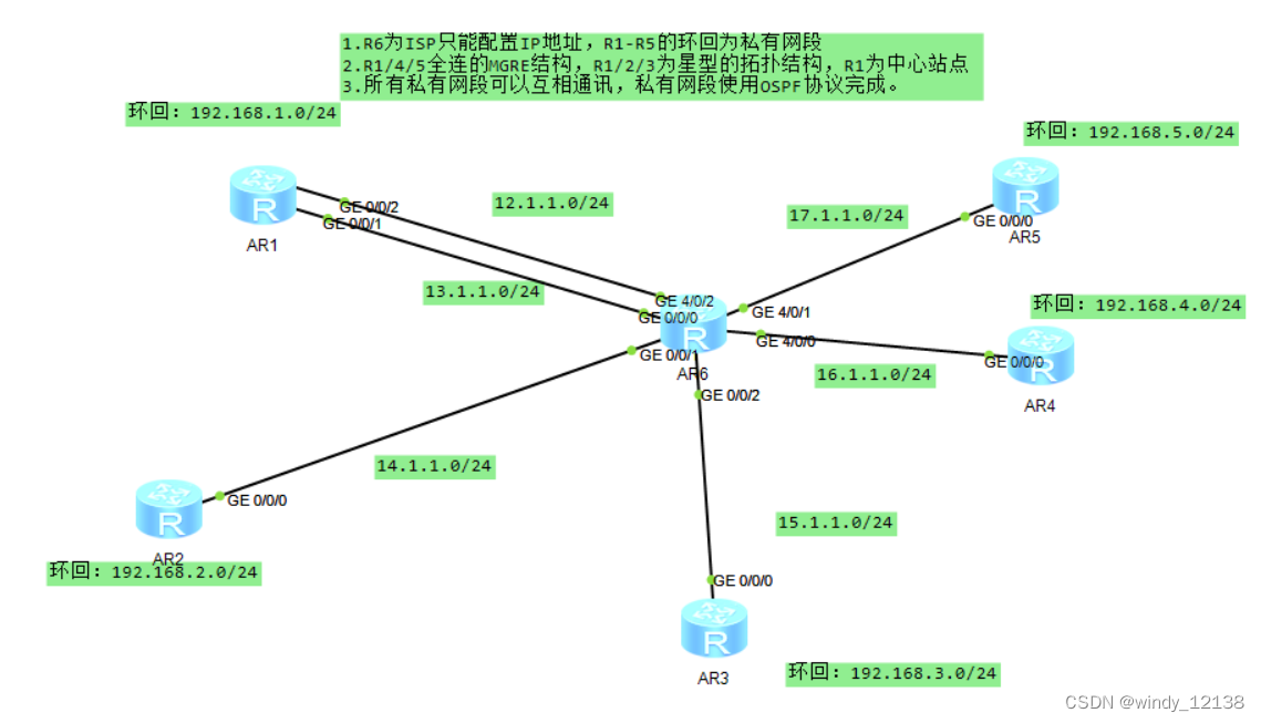
1.R6为ISP只能配置IP地址,R1-R5的环回为私有网段
2.R1/4/5全连的MGRE结构,R1/2/3为星型的拓扑结构,R1为中心站点
3.所有私有网段可以互相通讯,私有网段使用OSPF协议完成。
实验步骤:
首先:对各个路由器的ip地址进行配置 虚拟接口都规划好。
拓扑图如下:
首先:
我们先配置R1对R2 R3的基本要求:
interface Tunnel0/0/0
ip address 10.1.1.1 255.255.255.0
tunnel-protocol gre p2mp
source 13.1.1.1
ospf network-type broadcast
nhrp entry multicast dynamic
nhrp network-id 100
在R2中:
interface Tunnel0/0/0
ip address 10.1.1.2 255.255.255.0
tunnel-protocol gre p2mp
source GigabitEthernet0/0/0
ospf network-type broadcast
ospf dr-priority 0
nhrp network-id 100
nhrp entry 10.1.1.1 13.1.1.1 register
在R3中:
interface Tunnel0/0/0
ip address 10.1.1.3 255.255.255.0
tunnel-protocol gre p2mp
source GigabitEthernet0/0/0
ospf network-type broadcast
ospf dr-priority 0
nhrp network-id 100
nhrp entry 10.1.1.1 13.1.1.1 register
在R4中:
interface Tunnel0/0/1
ip address 11.1.1.2 255.255.255.0
tunnel-protocol gre p2mp
source 16.1.1.1 本地物理接口
ospf network-type broadcast 使用broadcast
nhrp entry multicast dynamic 声明中心
nhrp network-id 100
nhrp entry 11.1.1.1 12.1.1.1 register 去哪个地方注册 前ip是虚拟的 后ip是真实的
nhrp entry 11.1.1.3 17.1.1.1 register
在R5中:
interface Tunnel0/0/1
ip address 11.1.1.3 255.255.255.0
tunnel-protocol gre p2mp
source 17.1.1.1
ospf network-type broadcast
nhrp entry multicast dynamic
nhrp network-id 100
nhrp entry 11.1.1.1 12.1.1.1 register
在R6中:
interface GigabitEthernet0/0/0
ip address 13.1.1.2 255.255.255.0
#
interface GigabitEthernet0/0/1
ip address 14.1.1.2 255.255.255.0
#
interface GigabitEthernet0/0/2
ip address 15.1.1.2 255.255.255.0
#
interface GigabitEthernet4/0/0
ip address 16.1.1.2 255.255.255.0
#
interface GigabitEthernet4/0/1
ip address 17.1.1.2 255.255.255.0
#
interface GigabitEthernet4/0/2
ip address 12.1.1.2 255.255.255.0
当我们在配置完成之后,就会在
R1中显示:
[r1]ospf 1 router-id 1.1.1.1
[r1-ospf-1]area 0
[r1-ospf-1-area-0.0.0.0]display this
network 10.1.1.1 0.0.0.0 这是声明虚拟接口的
network 11.1.1.1 0.0.0.0
network 192.168.1.1 0.0.0.0 声明环回地址
使用ospf进行接口上的宣告
R2
[r2]ospf 1 router-id 2.2.2.2
[r2-ospf-1]area 0
[r2-ospf-1-area-0.0.0.0]display this
area 0.0.0.0
network 10.1.1.2 0.0.0.0
network 192.168.2.1 0.0.0.0
对R2的接口进行宣告
R3
[r3]ospf 1 router-id 3.3.3.3
[r3-ospf-1]area 0
[r3-ospf-1-area-0.0.0.0]display this
area 0.0.0.0
network 10.1.1.3 0.0.0.0
network 190.168.3.1 0.0.0.0
对R3的接口进行宣告
R4
[r4]ospf 1 router-id 4.4.4.4
[r4-ospf-1]area 0
[r4-ospf-1-area-0.0.0.0]display this
area 0.0.0.0
network 11.1.1.2 0.0.0.0
network 192.168.4.1 0.0.0.0
对R4的接口进行宣告
R5
[r5]ospf 1 router-id 5.5.5.5
[r5-ospf-1]area 0
[r5-ospf-1-area-0.0.0.0]display this
area 0.0.0.0
network 11.1.1.3 0.0.0.0
network 192.168.5.1 0.0.0.0
对R5的接口进行宣告
其中R1R2R3中是星型拓扑
这其中就需要对R2R3的DR进行优化不抢占 R1的DR
命令就是:
[r2-Tunnel0/0/0]ospf dr-priority 0
[r3-Tunnel0/0/0]ospf dr-priority 0
接下来就是对ospf的广播方式从P2P 到broadcast
[r1-Tunnel0/0/0]ospf network-type broadcast
[r2-Tunnel0/0/0]ospf network-type broadcast
[r3-Tunnel0/0/0]ospf network-type broadcast
其次,R1 R4 R5之间是MGRE结构,R1 自然是认证点,R4 R5也需要相互认证
所以其中R4就需要在R5上再进行认证一次
具体命令如下:
int tunnel 0/0/1
nhrp entry multicast dynamic
nhrp entry 11.1.1.3 17.1.1.1 register
这样就大致完成了
接下来看看结果
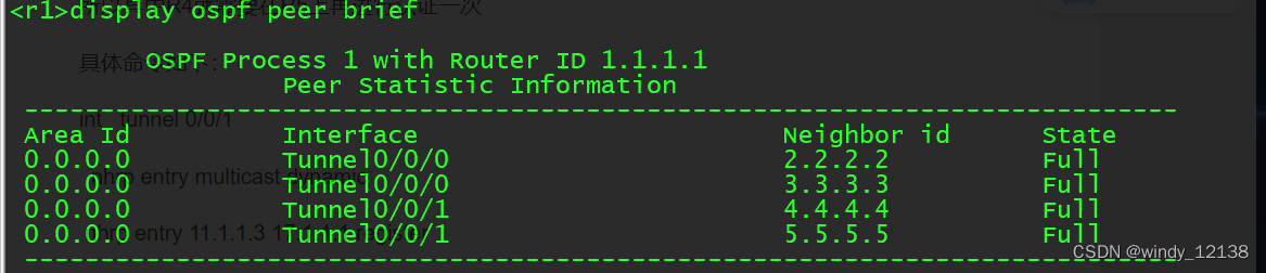
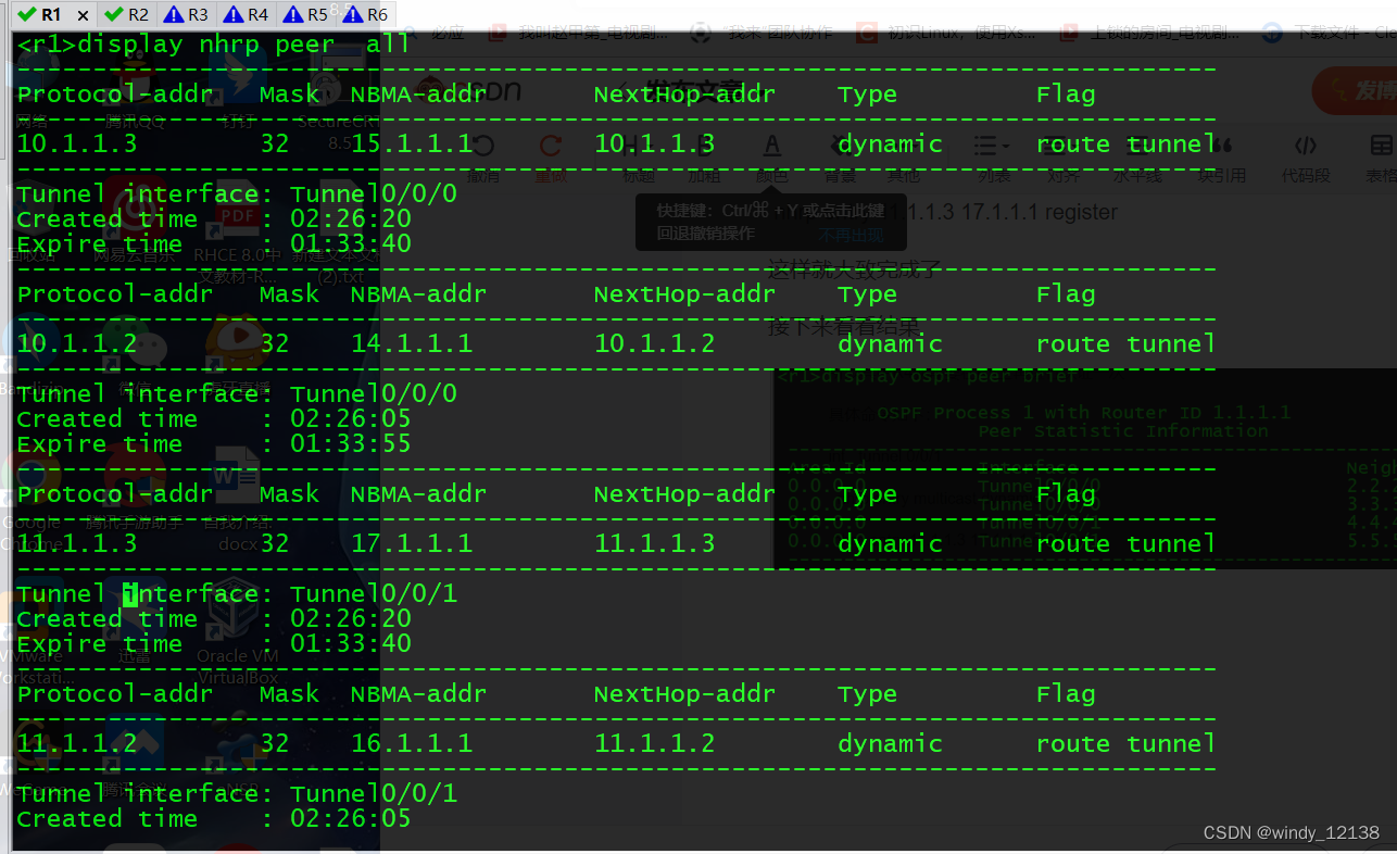
到这儿已经算是配置完成了
现在我们用任意的一个环回地址去ping其他的环回地址
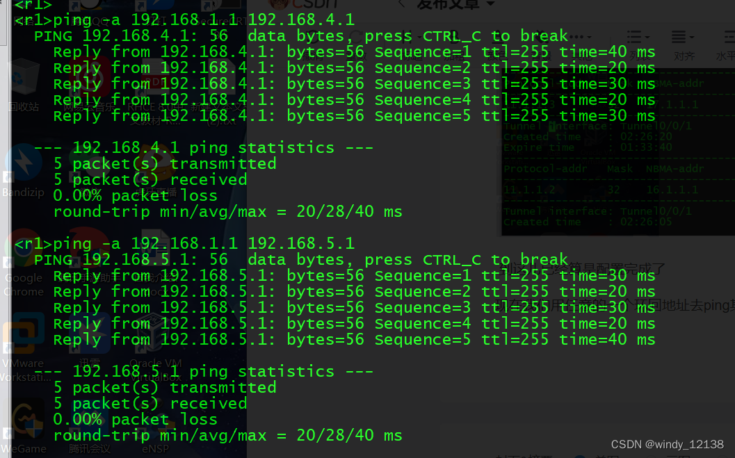

到目前,我们已经做完了
这个主要就是对于我们在上课时讲到的ospf中的星型结构 还有全连的MGRE的结构的综合实验。
整体实验还是比较基础,需要耐心的去完成即可。


 211
211


 被折叠的 条评论
为什么被折叠?
被折叠的 条评论
为什么被折叠?
 到【灌水乐园】发言


