


前段时间在闲着无聊时,学习了STM32HAL,对比起标准库,HAL用顺手之后更加快捷。
红外测温GY906,它与STM32通过IIC进行连接,接线引脚可以自己定义
在这里我的接线如下:
VCC->3.3V
GND->GND
SCL->PB8
SDA->PB9
直接上程序
GY906.c
#include "GY906.h"
#define ACK 0
#define NACK 1
#define SA 0x00
#define RAM_ACCESS 0x00
#define EEPROM_ACCESS 0x20
#define RAM_TOBJ1 0x07
#define SMBUS_SCK_H() HAL_GPIO_WritePin(GY_906_SCL_GPIO_Port,GY_906_SCL_Pin,GPIO_PIN_SET)
#define SMBUS_SCK_L() HAL_GPIO_WritePin(GY_906_SCL_GPIO_Port,GY_906_SCL_Pin,GPIO_PIN_RESET)
#define SMBUS_SDA_H() HAL_GPIO_WritePin(GY_906_SDA_GPIO_Port,GY_906_SDA_Pin,GPIO_PIN_SET)
#define SMBUS_SDA_L() HAL_GPIO_WritePin(GY_906_SDA_GPIO_Port,GY_906_SDA_Pin,GPIO_PIN_RESET)
#define SMBUS_SDA_PIN() HAL_GPIO_ReadPin(GY_906_SDA_GPIO_Port,GY_906_SDA_Pin)
void SMBus_StartBit(void)
{
SMBUS_SDA_H(); // Set SDA line
SMBus_Delay(5); // Wait a few microseconds
SMBUS_SCK_H(); // Set SCL line
SMBus_Delay(5); // Generate bus free time between Stop
SMBUS_SDA_L(); // Clear SDA line
SMBus_Delay(5); // Hold time after (Repeated) Start
SMBUS_SCK_L(); // Clear SCL line
SMBus_Delay(5); // Wait a few microseconds
}
void SMBus_StopBit(void)
{
SMBUS_SCK_L(); // Clear SCL line
SMBus_Delay(5); // Wait a few microseconds
SMBUS_SDA_L(); // Clear SDA line
SMBus_Delay(5); // Wait a few microseconds
SMBUS_SCK_H(); // Set SCL line
SMBus_Delay(5); // Stop condition setup time(Tsu:sto=4.0us min)
SMBUS_SDA_H(); // Set SDA line?úSCK=1ê±£??ì2aμ?SDAóé0μ?1±íê?í¨D??áê?£¨é?éy??£?
}
u8 SMBus_SendByte(u8 Tx_buffer)
{
u8 Bit_counter;
u8 Ack_bit;
u8 bit_out;
for(Bit_counter=8; Bit_counter; Bit_counter--)
{
if (Tx_buffer&0x80)
{
bit_out=1; // If the current bit of Tx_buffer is 1 set bit_out
}
else
{
bit_out=0; // else clear bit_out
}
SMBus_SendBit(bit_out); // Send the current bit on SDA
Tx_buffer<<=1; // Get next bit for checking
}
Ack_bit=SMBus_ReceiveBit(); // Get acknowledgment bit
return Ack_bit;
}
void SMBus_SendBit(u8 bit_out)
{
if(bit_out==0)
{
SMBUS_SDA_L();
}
else
{
SMBUS_SDA_H();
}
SMBus_Delay(2); // Tsu:dat = 250ns minimum
SMBUS_SCK_H(); // Set SCL line
SMBus_Delay(6); // High Level of Clock Pulse
SMBUS_SCK_L(); // Clear SCL line
SMBus_Delay(3); // Low Level of Clock Pulse
// SMBUS_SDA_H(); // Master release SDA line ,
return;
}
u8 SMBus_ReceiveBit(void)
{
u8 Ack_bit;
SMBUS_SDA_H(); //òy????ía2?μ?×èé?à-£?μ±×÷ê?è?
SMBus_Delay(2); // High Level of Clock Pulse
SMBUS_SCK_H(); // Set SCL line
SMBus_Delay(5); // High Level of Clock Pulse
if (SMBUS_SDA_PIN())
{
Ack_bit=1;
}
else
{
Ack_bit=0;
}
SMBUS_SCK_L(); // Clear SCL line
SMBus_Delay(3); // Low Level of Clock Pulse
return Ack_bit;
}
u8 SMBus_ReceiveByte(u8 ack_nack)
{
u8 RX_buffer;
u8 Bit_Counter;
for(Bit_Counter=8; Bit_Counter; Bit_Counter--)
{
if(SMBus_ReceiveBit()) // Get a bit from the SDA line
{
RX_buffer <<= 1; // If the bit is HIGH save 1 in RX_buffer
RX_buffer |=0x01;
}
else
{
RX_buffer <<= 1; // If the bit is LOW save 0 in RX_buffer
RX_buffer &=0xfe;
}
}
SMBus_SendBit(ack_nack); // Sends acknowledgment bit
return RX_buffer;
}
void SMBus_Delay(u32 time)
{
Coarse_delay_us(time);
}
void SMBus_Init()
{
SMBUS_SCK_H();
SMBUS_SDA_H();
}
u16 SMBus_ReadMemory(u8 slaveAddress, u8 command)
{
u16 data; // Data storage (DataH:DataL)
u8 Pec; // PEC byte storage
u8 DataL=0; // Low data byte storage
u8 DataH=0; // High data byte storage
u8 arr[6]; // Buffer for the sent bytes
u8 PecReg; // Calculated PEC byte storage
u8 ErrorCounter; // Defines the number of the attempts for communication with MLX90614
ErrorCounter=0x00; // Initialising of ErrorCounter
slaveAddress <<= 1; //2-7??±íê?′ó?úμ??·
do
{
repeat:
SMBus_StopBit(); //If slave send NACK stop comunication
--ErrorCounter; //Pre-decrement ErrorCounter
if(!ErrorCounter) //ErrorCounter=0?
{
break; //Yes,go out from do-while{}
}
SMBus_StartBit(); //Start condition
if(SMBus_SendByte(slaveAddress))//Send SlaveAddress ×?μí??Wr=0±íê??ó??à′D′?üá?
{
goto repeat; //Repeat comunication again
}
if(SMBus_SendByte(command)) //Send command
{
goto repeat; //Repeat comunication again
}
SMBus_StartBit(); //Repeated Start condition
if(SMBus_SendByte(slaveAddress+1)) //Send SlaveAddress ×?μí??Rd=1±íê??ó??à′?áêy?Y
{
goto repeat; //Repeat comunication again
}
DataL = SMBus_ReceiveByte(ACK); //Read low data,master must send ACK
DataH = SMBus_ReceiveByte(ACK); //Read high data,master must send ACK
Pec = SMBus_ReceiveByte(NACK); //Read PEC byte, master must send NACK
SMBus_StopBit(); //Stop condition
arr[5] = slaveAddress; //
arr[4] = command; //
arr[3] = slaveAddress+1; //Load array arr
arr[2] = DataL; //
arr[1] = DataH; //
arr[0] = 0; //
PecReg=PEC_Calculation(arr);//Calculate CRC
}
while(PecReg != Pec); //If received and calculated CRC are equal go out from do-while{}
data = (DataH<<8) | DataL; //data=DataH:DataL
return data;
}
u8 PEC_Calculation(u8 pec[])
{
u8 crc[6];
u8 BitPosition=47;
u8 shift;
u8 i;
u8 j;
u8 temp;
do
{
/*Load pattern value 0x000000000107*/
crc[5]=0;
crc[4]=0;
crc[3]=0;
crc[2]=0;
crc[1]=0x01;
crc[0]=0x07;
/*Set maximum bit position at 47 ( six bytes byte5...byte0,MSbit=47)*/
BitPosition=47;
/*Set shift position at 0*/
shift=0;
/*Find first "1" in the transmited message beginning from the MSByte byte5*/
i=5;
j=0;
while((pec[i]&(0x80>>j))==0 && i>0)
{
BitPosition--;
if(j<7)
{
j++;
}
else
{
j=0x00;
i--;
}
}/*End of while */
/*Get shift value for pattern value*/
shift=BitPosition-8;
/*Shift pattern value */
while(shift)
{
for(i=5; i<0xFF; i--)
{
if((crc[i-1]&0x80) && (i>0))
{
temp=1;
}
else
{
temp=0;
}
crc[i]<<=1;
crc[i]+=temp;
}/*End of for*/
shift--;
}/*End of while*/
/*Exclusive OR between pec and crc*/
for(i=0; i<=5; i++)
{
pec[i] ^=crc[i];
}/*End of for*/
}
while(BitPosition>8); /*End of do-while*/
return pec[0];
}
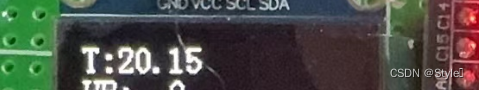
float SMBus_ReadTemp(void)
{
float temp;
temp = SMBus_ReadMemory(SA, RAM_ACCESS|RAM_TOBJ1)*0.02-273.15;
return temp;
}
在主函数里初始化后在while里直接读取就可以,最后结果如下
心率血氧传感器在测试花了很多时间,最后在大佬的指导下成功测出,推荐大家去学习 ,下面附上链接基于STM32以及HAL库的MAX30102模块使用+OLED显示(资源下载免费,在博主我的资源下载处)-CSDN博客z
接线如下
VVC->3.3
GND->GND
SCL->PB6
SDA->PB7
IM->PB4
#include "max30102.h"
#include "myiic.h"
#include "gpio.h"


uint32_t aun_ir_buffer[500]; //IR LED sensor data
int32_t n_ir_buffer_length;    //data length
uint32_t aun_red_buffer[500];    //Red LED sensor data
int32_t n_sp02; //SPO2 value
int8_t ch_spo2_valid;   //indicator to show if the SP02 calculation is valid
int32_t n_heart_rate;   //heart rate value
int8_t  ch_hr_valid;    //indicator to show if the heart rate calculation is valid
uint8_t uch_dummy;

//variables to calculate the on-board LED brightness that reflects the heartbeats
uint32_t un_min, un_max, un_prev_data;
int i;
int32_t n_brightness;
float f_temp;
uint8_t temp_num=0;
uint8_t temp[6];
uint8_t str[100];
uint8_t dis_hr=0,dis_spo2=0;
int flag1=0;
uint16_t sum[12];
uint16_t sum1[12];
int j,l,temp1,temp2;
int progess,flag3=0;
#define MAX_BRIGHTNESS 255


uint8_t max30102_Bus_Write(uint8_t Register_Address, uint8_t Word_Data)
{

	/* 采用串行EEPROM随即读取指令序列,连续读取若干字节 */

	/* 第1步:发起I2C总线启动信号 */
	IIC_Start();

	/* 第2步:发起控制字节,高7bit是地址,bit0是读写控制位,0表示写,1表示读 */
	IIC_Send_Byte(max30102_WR_address | I2C_WR);	/* 此处是写指令 */

	/* 第3步:发送ACK */
	if (IIC_Wait_Ack() != 0)
	{
		goto cmd_fail;	/* EEPROM器件无应答 */
	}

	/* 第4步:发送字节地址 */
	IIC_Send_Byte(Register_Address);
	if (IIC_Wait_Ack() != 0)
	{
		goto cmd_fail;	/* EEPROM器件无应答 */
	}

	/* 第5步:开始写入数据 */
	IIC_Send_Byte(Word_Data);

	/* 第6步:发送ACK */
	if (IIC_Wait_Ack() != 0)
	{
		goto cmd_fail;	/* EEPROM器件无应答 */
	}

	/* 发送I2C总线停止信号 */
	IIC_Stop();
	return 1;	/* 执行成功 */

cmd_fail: /* 命令执行失败后,切记发送停止信号,避免影响I2C总线上其他设备 */
	/* 发送I2C总线停止信号 */
	IIC_Stop();
	return 0;
}


uint8_t max30102_Bus_Read(uint8_t Register_Address)
{
	uint8_t  data;


	/* 第1步:发起I2C总线启动信号 */
	IIC_Start();

	/* 第2步:发起控制字节,高7bit是地址,bit0是读写控制位,0表示写,1表示读 */
	IIC_Send_Byte(max30102_WR_address | I2C_WR);	/* 此处是写指令 */

	/* 第3步:发送ACK */
	if (IIC_Wait_Ack() != 0)
	{
		goto cmd_fail;	/* EEPROM器件无应答 */
	}

	/* 第4步:发送字节地址, */
	IIC_Send_Byte((uint8_t)Register_Address);
	if (IIC_Wait_Ack() != 0)
	{
		goto cmd_fail;	/* EEPROM器件无应答 */
	}


	/* 第6步:重新启动I2C总线。下面开始读取数据 */
	IIC_Start();

	/* 第7步:发起控制字节,高7bit是地址,bit0是读写控制位,0表示写,1表示读 */
	IIC_Send_Byte(max30102_WR_address | I2C_RD);	/* 此处是读指令 */

	/* 第8步:发送ACK */
	if (IIC_Wait_Ack() != 0)
	{
		goto cmd_fail;	/* EEPROM器件无应答 */
	}

	/* 第9步:读取数据 */
	{
		data = IIC_Read_Byte(0);	/* 读1个字节 */

		IIC_NAck();	/* 最后1个字节读完后,CPU产生NACK信号(驱动SDA = 1) */
	}
	/* 发送I2C总线停止信号 */
	IIC_Stop();
	return data;	/* 执行成功 返回data值 */

cmd_fail: /* 命令执行失败后,切记发送停止信号,避免影响I2C总线上其他设备 */
	/* 发送I2C总线停止信号 */
	IIC_Stop();
	return 0;
}


void max30102_FIFO_ReadWords(uint8_t Register_Address,uint16_t Word_Data[][2],uint8_t count)
{
	uint8_t i=0;
	uint8_t no = count;
	uint8_t data1, data2;
	/* 第1步:发起I2C总线启动信号 */
	IIC_Start();

	/* 第2步:发起控制字节,高7bit是地址,bit0是读写控制位,0表示写,1表示读 */
	IIC_Send_Byte(max30102_WR_address | I2C_WR);	/* 此处是写指令 */

	/* 第3步:发送ACK */
	if (IIC_Wait_Ack() != 0)
	{
		goto cmd_fail;	/* EEPROM器件无应答 */
	}

	/* 第4步:发送字节地址, */
	IIC_Send_Byte((uint8_t)Register_Address);
	if (IIC_Wait_Ack() != 0)
	{
		goto cmd_fail;	/* EEPROM器件无应答 */
	}


	/* 第6步:重新启动I2C总线。下面开始读取数据 */
	IIC_Start();

	/* 第7步:发起控制字节,高7bit是地址,bit0是读写控制位,0表示写,1表示读 */
	IIC_Send_Byte(max30102_WR_address | I2C_RD);	/* 此处是读指令 */

	/* 第8步:发送ACK */
	if (IIC_Wait_Ack() != 0)
	{
		goto cmd_fail;	/* EEPROM器件无应答 */
	}

	/* 第9步:读取数据 */
	while (no)
	{
		data1 = IIC_Read_Byte(0);
		IIC_Ack();
		data2 = IIC_Read_Byte(0);
		IIC_Ack();
		Word_Data[i][0] = (((uint16_t)data1 << 8) | data2);  //


		data1 = IIC_Read_Byte(0);
		IIC_Ack();
		data2 = IIC_Read_Byte(0);
		if(1==no)
			IIC_NAck();	/* 最后1个字节读完后,CPU产生NACK信号(驱动SDA = 1) */
		else
			IIC_Ack();
		Word_Data[i][1] = (((uint16_t)data1 << 8) | data2);

		no--;
		i++;
	}
	/* 发送I2C总线停止信号 */
	IIC_Stop();

cmd_fail: /* 命令执行失败后,切记发送停止信号,避免影响I2C总线上其他设备 */
	/* 发送I2C总线停止信号 */
	IIC_Stop();
}

void max30102_FIFO_ReadBytes(uint8_t Register_Address,uint8_t* Data)
{
	max30102_Bus_Read(REG_INTR_STATUS_1);
	max30102_Bus_Read(REG_INTR_STATUS_2);

	/* 第1步:发起I2C总线启动信号 */
	IIC_Start();

	/* 第2步:发起控制字节,高7bit是地址,bit0是读写控制位,0表示写,1表示读 */
	IIC_Send_Byte(max30102_WR_address | I2C_WR);	/* 此处是写指令 */

	/* 第3步:发送ACK */
	if (IIC_Wait_Ack() != 0)
	{
		goto cmd_fail;	/* EEPROM器件无应答 */
	}

	/* 第4步:发送字节地址, */
	IIC_Send_Byte((uint8_t)Register_Address);
	if (IIC_Wait_Ack() != 0)
	{
		goto cmd_fail;	/* EEPROM器件无应答 */
	}


	/* 第6步:重新启动I2C总线。下面开始读取数据 */
	IIC_Start();

	/* 第7步:发起控制字节,高7bit是地址,bit0是读写控制位,0表示写,1表示读 */
	IIC_Send_Byte(max30102_WR_address | I2C_RD);	/* 此处是读指令 */

	/* 第8步:发送ACK */
	if (IIC_Wait_Ack() != 0)
	{
		goto cmd_fail;	/* EEPROM器件无应答 */
	}

	/* 第9步:读取数据 */
	Data[0] = IIC_Read_Byte(1);
	Data[1] = IIC_Read_Byte(1);
	Data[2] = IIC_Read_Byte(1);
	Data[3] = IIC_Read_Byte(1);
	Data[4] = IIC_Read_Byte(1);
	Data[5] = IIC_Read_Byte(0);
	/* 最后1个字节读完后,CPU产生NACK信号(驱动SDA = 1) */
	/* 发送I2C总线停止信号 */
	IIC_Stop();

cmd_fail: /* 命令执行失败后,切记发送停止信号,避免影响I2C总线上其他设备 */
	/* 发送I2C总线停止信号 */
	IIC_Stop();

//	uint8_t i;
//	uint8_t fifo_wr_ptr;
//	uint8_t firo_rd_ptr;
//	uint8_t number_tp_read;
//	//Get the FIFO_WR_PTR
//	fifo_wr_ptr = max30102_Bus_Read(REG_FIFO_WR_PTR);
//	//Get the FIFO_RD_PTR
//	firo_rd_ptr = max30102_Bus_Read(REG_FIFO_RD_PTR);
//
//	number_tp_read = fifo_wr_ptr - firo_rd_ptr;
//
//	//for(i=0;i<number_tp_read;i++){
//	if(number_tp_read>0){
//		IIC_ReadBytes(max30102_WR_address,REG_FIFO_DATA,Data,6);
//	}

	//max30102_Bus_Write(REG_FIFO_RD_PTR,fifo_wr_ptr);
}

void max30102_init(void)
{
//	GPIO_InitTypeDef GPIO_InitStructure;

// 	RCC_APB2PeriphClockCmd(RCC_APB2Periph_GPIOB,ENABLE);
//	GPIO_InitStructure.GPIO_Pin  = GPIO_Pin_14;
//	GPIO_InitStructure.GPIO_Mode = GPIO_Mode_IPU;
// 	GPIO_Init(GPIOB, &GPIO_InitStructure);

//	IIC_Init();

	max30102_reset();

//	max30102_Bus_Write(REG_MODE_CONFIG, 0x0b);  //mode configuration : temp_en[3]      MODE[2:0]=010 HR only enabled    011 SP02 enabled
//	max30102_Bus_Write(REG_INTR_STATUS_2, 0xF0); //open all of interrupt
//	max30102_Bus_Write(REG_INTR_STATUS_1, 0x00); //all interrupt clear
//	max30102_Bus_Write(REG_INTR_ENABLE_2, 0x02); //DIE_TEMP_RDY_EN
//	max30102_Bus_Write(REG_TEMP_CONFIG, 0x01); //SET   TEMP_EN

//	max30102_Bus_Write(REG_SPO2_CONFIG, 0x47); //SPO2_SR[4:2]=001  100 per second    LED_PW[1:0]=11  16BITS

//	max30102_Bus_Write(REG_LED1_PA, 0x47);
//	max30102_Bus_Write(REG_LED2_PA, 0x47);


	max30102_Bus_Write(REG_INTR_ENABLE_1,0xc0);	// INTR setting
	max30102_Bus_Write(REG_INTR_ENABLE_2,0x00);
	max30102_Bus_Write(REG_FIFO_WR_PTR,0x00);  	//FIFO_WR_PTR[4:0]
	max30102_Bus_Write(REG_OVF_COUNTER,0x00);  	//OVF_COUNTER[4:0]
	max30102_Bus_Write(REG_FIFO_RD_PTR,0x00);  	//FIFO_RD_PTR[4:0]
	max30102_Bus_Write(REG_FIFO_CONFIG,0x0f);  	//sample avg = 1, fifo rollover=false, fifo almost full = 17
	max30102_Bus_Write(REG_MODE_CONFIG,0x03);  	//0x02 for Red only, 0x03 for SpO2 mode 0x07 multimode LED
	max30102_Bus_Write(REG_SPO2_CONFIG,0x27);  	// SPO2_ADC range = 4096nA, SPO2 sample rate (100 Hz), LED pulseWidth (400uS)
	max30102_Bus_Write(REG_LED1_PA,0x24);   	//Choose value for ~ 7mA for LED1
	max30102_Bus_Write(REG_LED2_PA,0x24);   	// Choose value for ~ 7mA for LED2
	max30102_Bus_Write(REG_PILOT_PA,0x7f);   	// Choose value for ~ 25mA for Pilot LED


//	// Interrupt Enable 1 Register. Set PPG_RDY_EN (data available in FIFO)
//	max30102_Bus_Write(0x2, 1<<6);

//	// FIFO configuration register
//	// SMP_AVE: 16 samples averaged per FIFO sample
//	// FIFO_ROLLOVER_EN=1
//	//max30102_Bus_Write(0x8,  1<<4);
//	max30102_Bus_Write(0x8, (0<<5) | 1<<4);

//	// Mode Configuration Register
//	// SPO2 mode
//	max30102_Bus_Write(0x9, 3);

//	// SPO2 Configuration Register
//	max30102_Bus_Write(0xa,
//			(3<<5)  // SPO2_ADC_RGE 2 = full scale 8192 nA (LSB size 31.25pA); 3 = 16384nA
//			| (1<<2) // sample rate: 0 = 50sps; 1 = 100sps; 2 = 200sps
//			| (3<<0) // LED_PW 3 = 411μs, ADC resolution 18 bits
//	);

//	// LED1 (red) power (0 = 0mA; 255 = 50mA)
//	max30102_Bus_Write(0xc, 0xb0);

//	// LED (IR) power
//	max30102_Bus_Write(0xd, 0xa0);

}

void max30102_reset(void)
{
	max30102_Bus_Write(REG_MODE_CONFIG,0x40);
	max30102_Bus_Write(REG_MODE_CONFIG,0x40);
}


void maxim_max30102_write_reg(uint8_t uch_addr, uint8_t uch_data)
{
//  char ach_i2c_data[2];
//  ach_i2c_data[0]=uch_addr;
//  ach_i2c_data[1]=uch_data;
//
//  IIC_WriteBytes(I2C_WRITE_ADDR, ach_i2c_data, 2);
	IIC_Write_One_Byte(I2C_WRITE_ADDR,uch_addr,uch_data);
}

void maxim_max30102_read_reg(uint8_t uch_addr, uint8_t *puch_data)
{
//  char ch_i2c_data;
//  ch_i2c_data=uch_addr;
//  IIC_WriteBytes(I2C_WRITE_ADDR, &ch_i2c_data, 1);
//
//  i2c.read(I2C_READ_ADDR, &ch_i2c_data, 1);
//
//   *puch_data=(uint8_t) ch_i2c_data;

	IIC_Read_One_Byte(I2C_WRITE_ADDR,uch_addr,puch_data);
}

void maxim_max30102_read_fifo(uint32_t *pun_red_led, uint32_t *pun_ir_led)
{

	unsigned char uch_temp;
	char ach_i2c_data[6];
	*pun_red_led=0;
	*pun_ir_led=0;


  //read and clear status register
  maxim_max30102_read_reg(REG_INTR_STATUS_1, &uch_temp);
  maxim_max30102_read_reg(REG_INTR_STATUS_2, &uch_temp);

  IIC_ReadBytes(I2C_WRITE_ADDR,REG_FIFO_DATA,(uint8_t *)ach_i2c_data,6);

  un_temp=(unsigned char) ach_i2c_data[0];
  un_temp<<=16;
  *pun_red_led+=un_temp;
  un_temp=(unsigned char) ach_i2c_data[1];
  un_temp<<=8;
  *pun_red_led+=un_temp;
  un_temp=(unsigned char) ach_i2c_data[2];
  *pun_red_led+=un_temp;

  un_temp=(unsigned char) ach_i2c_data[3];
  un_temp<<=16;
  *pun_ir_led+=un_temp;
  un_temp=(unsigned char) ach_i2c_data[4];
  un_temp<<=8;
  *pun_ir_led+=un_temp;
  un_temp=(unsigned char) ach_i2c_data[5];
  *pun_ir_led+=un_temp;
  *pun_red_led&=0x03FFFF;  //Mask MSB [23:18]
  *pun_ir_led&=0x03FFFF;  //Mask MSB [23:18]
}


void dis_DrawCurve(uint32_t* data,uint8_t x)
{
	uint16_t i;
	uint32_t max=0,min=262144;
	uint32_t temp;
	uint32_t compress;

	for(i=0;i<128*2;i++)
	{
		if(data[i]>max)
		{
			max = data[i];
		}
		if(data[i]<min)
		{
			min = data[i];
		}
	}

	compress = (max-min)/20;

	for(i=0;i<128;i++)
	{
		temp = data[i*2] + data[i*2+1];
		temp/=2;
		temp -= min;
		temp/=compress;
		if(temp>20)temp=20;
	}
}


void MAX30102_data_set()
{
//	printf("\r\n MAX30102  init  \r\n");

	un_min=0x3FFFF;
	un_max=0;

	n_ir_buffer_length=500; //buffer length of 100 stores 5 seconds of samples running at 100sps
	//read the first 500 samples, and determine the signal range
    for(i=0;i<n_ir_buffer_length;i++)
    {
       while(MAX30102_INT==1);   //wait until the interrupt pin asserts

		max30102_FIFO_ReadBytes(REG_FIFO_DATA,temp);
		aun_red_buffer[i] =  (long)((long)((long)temp[0]&0x03)<<16) | (long)temp[1]<<8 | (long)temp[2];    // Combine values to get the actual number
		aun_ir_buffer[i] = (long)((long)((long)temp[3] & 0x03)<<16) |(long)temp[4]<<8 | (long)temp[5];   // Combine values to get the actual number

        if(un_min>aun_red_buffer[i])
            un_min=aun_red_buffer[i];    //update signal min
        if(un_max<aun_red_buffer[i])
            un_max=aun_red_buffer[i];    //update signal max
    }
	un_prev_data=aun_red_buffer[i];
	//calculate heart rate and SpO2 after first 500 samples (first 5 seconds of samples)
    maxim_heart_rate_and_oxygen_saturation(aun_ir_buffer, n_ir_buffer_length, aun_red_buffer, &n_sp02, &ch_spo2_valid, &n_heart_rate, &ch_hr_valid);
}


void MAX30102_get(uint8_t *hr,uint8_t *spo2)
{
	    i=0;
        un_min=0x3FFFF;
        un_max=0;

		//dumping the first 100 sets of samples in the memory and shift the last 400 sets of samples to the top
        for(i=100;i<500;i++)
        {
            aun_red_buffer[i-100]=aun_red_buffer[i];
            aun_ir_buffer[i-100]=aun_ir_buffer[i];

            //update the signal min and max
            if(un_min>aun_red_buffer[i])
            un_min=aun_red_buffer[i];
            if(un_max<aun_red_buffer[i])
            un_max=aun_red_buffer[i];
        }
		//take 100 sets of samples before calculating the heart rate.
        for(i=400;i<500;i++)
        {
            un_prev_data=aun_red_buffer[i-1];
            while(MAX30102_INT==1);

            max30102_FIFO_ReadBytes(REG_FIFO_DATA,temp);
			aun_red_buffer[i] =  (long)((long)((long)temp[0]&0x03)<<16) | (long)temp[1]<<8 | (long)temp[2];    // Combine values to get the actual number
			aun_ir_buffer[i] = (long)((long)((long)temp[3] & 0x03)<<16) |(long)temp[4]<<8 | (long)temp[5];   // Combine values to get the actual number

            if(aun_red_buffer[i]>un_prev_data)
            {
                f_temp=aun_red_buffer[i]-un_prev_data;
                f_temp/=(un_max-un_min);
                f_temp*=MAX_BRIGHTNESS;
                n_brightness-=(int)f_temp;
                if(n_brightness<0)
                    n_brightness=0;
            }
            else
            {
                f_temp=un_prev_data-aun_red_buffer[i];
                f_temp/=(un_max-un_min);
                f_temp*=MAX_BRIGHTNESS;
                n_brightness+=(int)f_temp;
                if(n_brightness>MAX_BRIGHTNESS)
                    n_brightness=MAX_BRIGHTNESS;
            }


			if(ch_hr_valid == 1 && n_heart_rate<150&&n_heart_rate>60&&aun_red_buffer[i]>50000&&ch_spo2_valid==1&&aun_ir_buffer[i]>120000)
			{
				 sum[j] = n_heart_rate;
                 sum1[j]=n_sp02;
		    }

			if(j==11)
			{
				for(j = 1;j <10;j++)
				{
					for(l = j+1;l <10;l++)
					{
						if(sum[l] < sum[j])
						{
							temp1 = sum[j];
							sum[j] = sum[l];
							sum[l] = temp1;
						}
							if(sum1[l] < sum1[j])
						{
							temp2 = sum1[j];
							sum1[j] = sum1[l];
							sum1[l] = temp2;
						}
					}
				}
				dis_hr=sum[1];
				dis_spo2=sum1[8];
				j = 0;
			 }

     	    *hr = dis_hr;
			*spo2 = dis_spo2;

			if(progess==100)
			flag3=1;

		}

        if(sum[j]!=0)
		{
			if(progess!=100&&j!=0)
	        progess+=10;

			j++;
		}
        maxim_heart_rate_and_oxygen_saturation(aun_ir_buffer, n_ir_buffer_length, aun_red_buffer, &n_sp02, &ch_spo2_valid, &n_heart_rate, &ch_hr_valid);
		//send samples and calculation result to terminal program through UART


		//显示刷新
//		LED0=0;
		if(dis_hr == 0 && dis_spo2 == 0)  //**dis_hr == 0 && dis_spo2 == 0
		{
			sprintf((char *)str,"HR:--- SpO2:--- ");//**HR:--- SpO2:---
		}
		else{
			sprintf((char *)str,"HR:%3d SpO2:%3d ",dis_hr,dis_spo2);//**HR:%3d SpO2:%3d
		}

		//红光在上,红外在下
		dis_DrawCurve(aun_red_buffer,20);
		dis_DrawCurve(aun_ir_buffer,0);


}
结果如下
![]()
如有错误,欢迎各位大佬指导学习
其中OLED和DS1302的程序后面更新


 4002
4002


 被折叠的 条评论
为什么被折叠?
被折叠的 条评论
为什么被折叠?
 到【灌水乐园】发言


