


概述
VPN(Virtual Private Network,虚拟专用网络)指的是在一个公共网络中实现虚拟的专用网络,从而使得用户能够基于该专用网络实现通信的技术。MPLS VPN也是VPN技术中的一种。本文特指BGP/MPLS IP VPN。
BGP/MPLS IP VPN网络一般由运营商搭建,VPN用户购买VPN服务来实现用户网络之间的路由传递、数据互通等。MPLS VPN的骨干网也可以由企业自行搭建,技术层面与运营商搭建基本一致。
MPLS VPN使用BGP在运营商骨干网(IP网络)上发布VPN路由,使用MPLS在运营商骨干网上转发VPN报文。BGP/MPLS IP VPN又被简称为MPLS VPN,是一种常见的L3VPN(Layer 3 VPN)技术。
网络架构
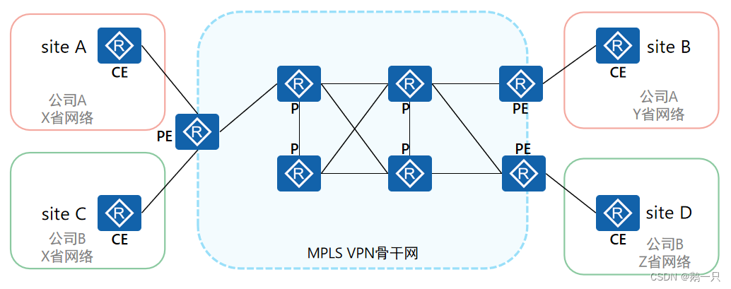
MPLS VPN网络架构由三部分组成:
CE(Customer Edge):用户网络边缘设备,有接口直接与运营商网络相连。CE可以是路由器或交换机,也可以是一台主机。通常情况下,CE“感知”不到VPN的存在,也不需要支持MPLS。
PE(Provider Edge):运营商边缘路由器,是运营商网络的边缘设备,与CE直接相连。在MPLS网络中,对VPN的所有处理都发生在PE上,对PE性能要求较高。
P(Provider):运营商网络中的骨干路由器,不与CE直接相连。P设备只需要具备基本MPLS转发能力,不维护VPN相关信息。
站点(site)就是MPLS VPN的用户,由CE和其他用户设备构成。站点的特性是相互之间具备IP连通性的一组IP系统,并且这组IP系统的IP连通性不需通过运营商网络实现。
技术架构
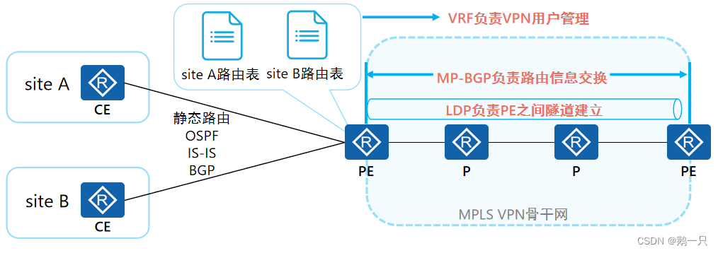
MPLS VPN是多种技术结合的综合解决方案,主要包含:
MP-BGP(MultiProtocol BGP):负责在PE与PE之间传递站点内的路由信息。
LDP:负责PE与PE之间的隧道建立
VRF:负责PE的VPN用户管理。
静态路由、IGP、BGP:负责PE与CE之间的路由信息交换。
常见组网方案
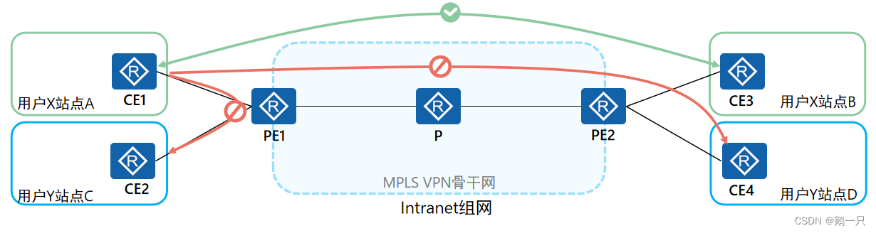
Intranet:一个VPN中的所有用户形成闭合用户群,同一VPN站点之间可以互访,不同VPN站点间不能互访。Intranet组网是最简单也是最典型的MPLS VPN组网方案。可以通过配置单个RD来实现Intranet组网方案。
Extranet:适用于一个VPN用户希望提供部分本VPN的站点资源给其他VPN的用户访问的场景。可以通过配置多个RD来实现Extranet组网方案。
Hub&Spoke:如果希望在VPN中设置中心访问控制设备,其它用户的互访都通过中心访问控制设备进行,可采用Hub&Spoke组网方案。
路由交互
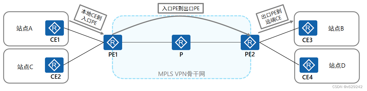
若想实现同一个VPN的不同站点之间的通信,首先需要完成不同站点之间的路由交互。在基本MPLS VPN组网中,VPN路由信息的发布涉及CE和PE,P路由器只维护骨干网的路由,不需要了解任何VPN路由信息。VPN路由信息的发布过程包括三部分: 1、本地CE到入口PE 2、入口PE到出口PE 3、出口PE到远端CE
CE与PE之间的路由信息交换
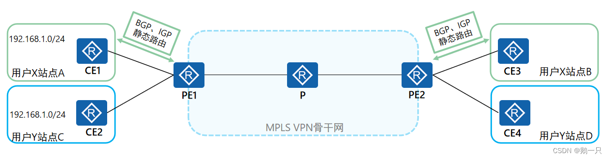
CE与PE之间可以使用静态路由、OSPF、IS-IS或BGP交换路由信息。无论使用哪种路由协议,CE和PE之间交换的都是标准的IPv4路由。
本地CE到入口PE和出口PE到远端CE的路由信息交换原理完全相同。
VRF

VRF(Virtual Routing and Forwarding,虚拟路由转发),又称VPN实例,是MPLS VPN架构中的关键技术,每个VPN实例使用独立的路由转发表项,实现VPN之间的逻辑隔离。解决了不同的用户使用重叠IP地址空间的问题。
相关命令
开启VPN实例功能并进入视图
[PE1]ip vpn-instance VPN1在接口下绑定VPN实例
[PE1-GigabitEthernet0/0/1]ip binding vpn-instance VPN1RD
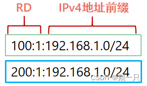
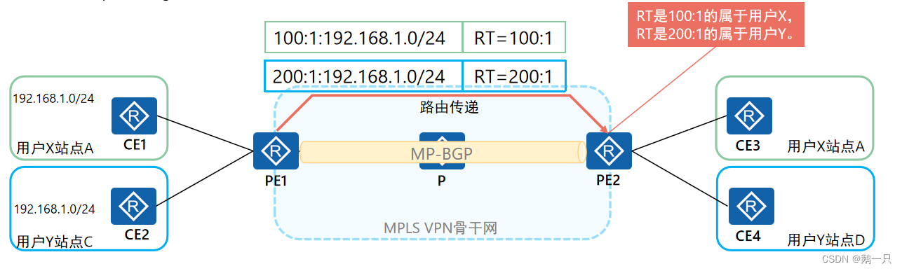
PE收到不同VPN的CE发来的IPv4地址前缀,本地根据VPN实例配置去区分这些地址前缀。但是VPN实例只是一个本地的概念,PE无法将VPN实例信息传递到对端PE,故有了RD(Route Distinguisher,路由标识符)。
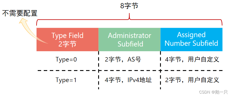
RD长8字节,用于区分使用相同地址空间的IPv4前缀。
PE从CE接收到IPv4路由后,在IPv4前缀前加上RD,转换为全局唯一的VPN-IPv4路由。
RD的配置格式有四种,常用的两种如下:
16bits自治系统号:32bits用户自定义数字(例如:100:1)。
32bits IPv4地址:16bits用户自定义数字(例如:172.1.1.1:1)。
相关命令
配置RD(VPN实例视图)
[PE1-vpn-instance-VPN1]route-distinguisher 100:1VPN-IPv4地址
VPN-IPv4地址又被称为VPNv4地址:VPNv4地址共有12个字节,包括8字节的路由标识符RD(Route Distinguisher)和4字节的IPv4地址前缀。
MP-BGP
为了正确处理VPN路由,MPLS VPN使用RFC2858(Multiprotocol Extensions for BGP-4)中规定的MP-BGP,即BGP-4的多协议扩展。 MP-BGP采用地址族(Address Family)来区分不同的网络层协议,既可以支持传统的IPv4地址族,又可以支持其它地址族(比如VPN-IPv4地址族、IPv6地址族等)。
相关命令
在MP-BGP中开启vpnv4功能(用来转换VPN-IPv4地址)
[PE1-bgp]ipv4-family vpnv4在MP-BGP的vpn4视图下指定对等体
[PE1-bgp-af-vpnv4]peer 3.3.3.3 enable 在MP-BGP中开启VPN实例(用来在CE与PE之间建立邻居关系)
[PE1-bgp]ipv4-family vpn-instance VPN1在MP-BGP的VPN实例视图下引入直连路由
[PE1-bgp-VPN1]import-routeMP-BGP新增了两种路径属性
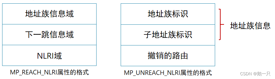
MP_REACH_NLRI:Multiprotocol Reachable NLRI,多协议可达NLRI。用于发布可达路由及下一跳信息。
MP_UNREACH_NLRI:Multiprotocol Unreachable NLRI,多协议不可达NLRI。用于撤销不可达路由。
地址族信息(Address Family Information)域:由2字节的地址族标识AFI(Address Family Identifier)和1字节的子地址族标识SAFI(Subsequent Address Family Identifier)组成。 AFI标识网络层协议,对应RFC3232的“Address Family Number”所定义的地址族值。例如IPv4的值是1,IPv6的值是2。 SAFI表示NLRI的类型。AFI值为1,SAFI值为128表示NLRI中的地址为MPLS-labeled VPN-IPv4地址。
下一跳信息(Next Hop Network Address Information)域:由一字节的下一跳网络地址长度和可变长度的下一跳网络地址组成。
网络层可达性信息(NLRI)域:由一个或多个三元组<长度、标签、前缀>组成 。
RT
MPLS VPN使用BGP扩展团体属性-VPN Target(也称为Route Target)来控制VPN路由信息的发布与接收。
在PE上,每一个VPN实例都会与一个或多个VPN Target属性绑定,有两类VPN Target属性:
Export Target(ERT):本地PE从直接相连站点学到IPv4路由后,转换为VPN IPv4路由,并为这些路由添加Export Target属性。Export Target属性作为BGP的扩展团体属性随路由发布。
Import Target(IRT):PE收到其它PE发布的VPN-IPv4路由时,检查其Export Target属性。当此属性与PE上某个VPN实例的Import Target匹配时,PE就把路由加入到该VPN实例的路由表。
配置VPN-Target时,只需要指定VPN-Target的Administrator子字段和Assigned Number子字段。VPN-Target的配置格式与RD格式一致。
相关命令
配置RT(VPN实例试图)
[PE1-vpn-instance-VPN1]vpn-target 100:100 ?
  STRING<3-21>         X.X.X.X:number<0-65535> or
                       number<0-65535>:number<0-4294967295> or
                       number<0-65535>.number<0-65535>:number<0-65535> or
                       <65536-4294967295>:<0-65535> but not support 0:0 and
                       0.0:0
  both                 Set export VPN-Target and import VPN-Target
  export-extcommunity  Set export VPN-Target
  import-extcommunity  Set import VPN-Target
  <cr>                 Please press ENTER to execute command
路由交互过程
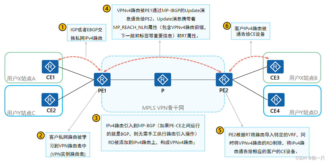
1 私网路由通过路由协议从CE传导到入口PE的VPN实例中。
2 VPN实例通过MP-BGP协议将路由从入口PE传导到出口PE。
3 PE之间通过MPLS LDP协议以及作为桥接的P设备进行标签转发。
配置举例:MPLS VPN地址重复(Intranet)
需求
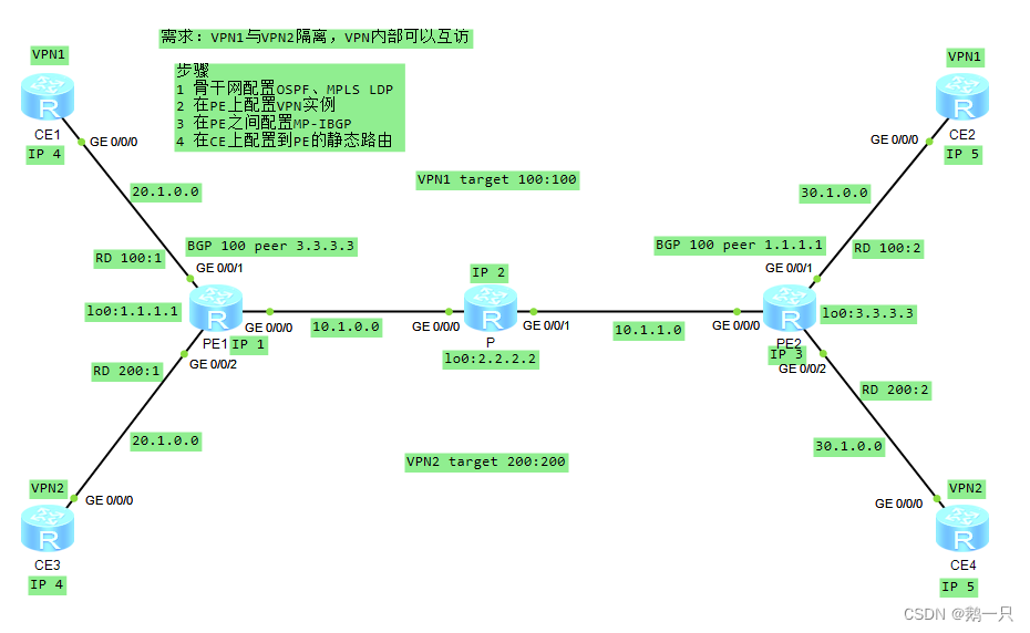
VPN1与VPN2隔离,VPN内部可以互访
步骤
1 骨干网配置OSPF、MPLS LDP
2 在PE上配置VPN实例
3 在PE之间配置MP-IBGP
4 在CE上配置到PE的静态路由
具体配置
PE1配置
#
 sysname PE1
#
ip vpn-instance VPN1                         \\配置VPN实例(包括RD、target等)
 ipv4-family
  route-distinguisher 100:1                  \\配置RD
  vpn-target 100:100 export-extcommunity     \\配置RT
  vpn-target 100:100 import-extcommunity
#
ip vpn-instance VPN2
 ipv4-family
  route-distinguisher 200:1
  vpn-target 200:200 export-extcommunity
  vpn-target 200:200 import-extcommunity
#
mpls lsr-id 1.1.1.1
mpls
#
mpls ldp                                    \\配置MPLS LDP(包括全局和接口)
#
interface GigabitEthernet0/0/0
 ip address 10.1.0.1 255.255.255.0
 ospf enable 1 area 0.0.0.0
 mpls
 mpls ldp
#
interface GigabitEthernet0/0/1
 ip binding vpn-instance VPN1               \\绑定VPN实例
 ip address 20.1.0.1 255.255.255.0
#
interface GigabitEthernet0/0/2
 ip binding vpn-instance VPN2
 ip address 20.1.0.1 255.255.255.0
#
interface LoopBack0
 ip address 1.1.1.1 255.255.255.255
 ospf enable 1 area 0.0.0.0
#
bgp 100                                     \\配置MP-IBGP(包括指定对等体、更新源接口)
 peer 3.3.3.3 as-number 100
 peer 3.3.3.3 connect-interface LoopBack0
 #
 ipv4-family unicast
  undo synchronization
  peer 3.3.3.3 enable
 #
 ipv4-family vpnv4                          \\在BGP中开启vpn4协议
  policy vpn-target                         \\此项如果undo,与对等体PE之间的路由交换将不受限
                                              也VPN之间也不受隔离,既没有RT的存在
  peer 3.3.3.3 enable
 #
 ipv4-family vpn-instance VPN1              \\在BGP中开启VPN实例
  import-route direct                       \\引入直连路由以便对等体访问
 #
 ipv4-family vpn-instance VPN2
  import-route direct
#
ospf 1 router-id 1.1.1.1
 area 0.0.0.0
#
PE2配置
#
 sysname PE2
#
ip vpn-instance VPN1
 ipv4-family
  route-distinguisher 100:2
  vpn-target 100:100 export-extcommunity
  vpn-target 100:100 import-extcommunity
#
ip vpn-instance VPN2
 ipv4-family
  route-distinguisher 200:2
  vpn-target 200:200 export-extcommunity
  vpn-target 200:200 import-extcommunity
#
mpls lsr-id 3.3.3.3
mpls
#
mpls ldp
#
interface GigabitEthernet0/0/0
 ip address 10.1.1.3 255.255.255.0
 ospf enable 1 area 0.0.0.0
 mpls
 mpls ldp
#
interface GigabitEthernet0/0/1
 ip binding vpn-instance VPN1
 ip address 30.1.0.3 255.255.255.0
#
interface GigabitEthernet0/0/2
 ip binding vpn-instance VPN2
 ip address 30.1.0.3 255.255.255.0
#
interface LoopBack0
 ip address 3.3.3.3 255.255.255.255
 ospf enable 1 area 0.0.0.0
#
bgp 100
 peer 1.1.1.1 as-number 100
 peer 1.1.1.1 connect-interface LoopBack0
 #
 ipv4-family unicast
  undo synchronization
  peer 1.1.1.1 enable
 #
 ipv4-family vpnv4
  policy vpn-target
  peer 1.1.1.1 enable
 #
 ipv4-family vpn-instance VPN1
  import-route direct
 #
 ipv4-family vpn-instance VPN2
  import-route direct
#
ospf 1 router-id 3.3.3.3
 area 0.0.0.0
#
P配置
#
 sysname P
#
mpls lsr-id 2.2.2.2
mpls
#
mpls ldp
#
interface GigabitEthernet0/0/0
 ip address 10.1.0.2 255.255.255.0
 mpls
 mpls ldp
#
interface GigabitEthernet0/0/1
 ip address 10.1.1.2 255.255.255.0
 mpls
 mpls ldp
#
interface LoopBack0
 ip address 2.2.2.2 255.255.255.255
#
ospf 1
 area 0.0.0.0
  network 0.0.0.0 255.255.255.255
#
CE1配置
#
 sysname CE1
#
interface GigabitEthernet0/0/0
 ip address 20.1.0.4 255.255.255.0
#
ip route-static 0.0.0.0 0.0.0.0 GigabitEthernet0/0/0 20.1.0.1  \\配置到PE的静态路由
#
CE2配置
#
 sysname CE2
#
interface GigabitEthernet0/0/0
 ip address 30.1.0.5 255.255.255.0
#
ip route-static 0.0.0.0 0.0.0.0 GigabitEthernet0/0/0 30.1.0.3
#
CE3配置
#
 sysname CE3
#
interface GigabitEthernet0/0/0
 ip address 20.1.0.4 255.255.255.0
#
ip route-static 0.0.0.0 0.0.0.0 GigabitEthernet0/0/0 20.1.0.1
#
CE4配置
#
 sysname CE4
#
interface GigabitEthernet0/0/0
 ip address 30.1.0.5 255.255.255.0
#
ip route-static 0.0.0.0 0.0.0.0 GigabitEthernet0/0/0 30.1.0.3
#
验证结果
查看MPLS LDP的建立情况
<PE1>display mpls ldp session

 LDP Session(s) in Public Network
 Codes: LAM(Label Advertisement Mode), SsnAge Unit(DDDD:HH:MM)
 A '*' before a session means the session is being deleted.
 ------------------------------------------------------------------------------
 PeerID             Status      LAM  SsnRole  SsnAge      KASent/Rcv
 ------------------------------------------------------------------------------
 2.2.2.2:0          Operational DU   Passive  0000:00:28  114/114
 ------------------------------------------------------------------------------
 TOTAL: 1 session(s) Found.


<PE1>display mpls ldp lsp

 LDP LSP Information
 -------------------------------------------------------------------------------
 DestAddress/Mask   In/OutLabel    UpstreamPeer    NextHop         OutInterface
 -------------------------------------------------------------------------------

 1.1.1.1/32         3/NULL         2.2.2.2         127.0.0.1       InLoop0
*1.1.1.1/32         Liberal/1024                   DS/2.2.2.2
 2.2.2.2/32         NULL/3         -               10.1.0.2        GE0/0/0
 2.2.2.2/32         1024/3         2.2.2.2         10.1.0.2        GE0/0/0
 3.3.3.3/32         NULL/1025      -               10.1.0.2        GE0/0/0
 3.3.3.3/32         1025/1025      2.2.2.2         10.1.0.2        GE0/0/0
 -------------------------------------------------------------------------------
 TOTAL: 5 Normal LSP(s) Found.
 TOTAL: 1 Liberal LSP(s) Found.
 TOTAL: 0 Frr LSP(s) Found.
 A '*' before an LSP means the LSP is not established
 A '*' before a Label means the USCB or DSCB is stale
 A '*' before a UpstreamPeer means the session is stale
 A '*' before a DS means the session is stale
 A '*' before a NextHop means the LSP is FRR LSP
查看VPN实例的配置情况
<PE1>display ip vpn-instance verbose
 Total VPN-Instances configured      : 2
 Total IPv4 VPN-Instances configured : 2
 Total IPv6 VPN-Instances configured : 0

 VPN-Instance Name and ID : VPN1, 1
  Interfaces : GigabitEthernet0/0/1
 Address family ipv4
  Create date : 2023/02/03 16:16:10 UTC-08:00
  Up time : 0 days, 00 hours, 32 minutes and 25 seconds
  Route Distinguisher : 100:1
  Export VPN Targets :  100:100
  Import VPN Targets :  100:100
  Label Policy : label per route
  Log Interval : 5

 VPN-Instance Name and ID : VPN2, 2
  Interfaces : GigabitEthernet0/0/2
 Address family ipv4
  Create date : 2023/02/03 16:16:10 UTC-08:00
  Up time : 0 days, 00 hours, 32 minutes and 25 seconds
  Route Distinguisher : 200:1
  Export VPN Targets :  200:200
  Import VPN Targets :  200:200
  Label Policy : label per route
  Log Interval : 5
查看BGP的建立状态
<PE1>display bgp peer

 BGP local router ID : 10.1.0.1
 Local AS number : 100
 Total number of peers : 1		  Peers in established state : 1

  Peer            V          AS  MsgRcvd  MsgSent  OutQ  Up/Down       State Pre
fRcv

  3.3.3.3         4         100       46       47     0 00:42:08 Established
   0
查看VPN实例路由表
<PE1>display ip routing-table vpn-instance VPN1
Route Flags: R - relay, D - download to fib
------------------------------------------------------------------------------
Routing Tables: VPN1
         Destinations : 5        Routes : 5

Destination/Mask    Proto   Pre  Cost      Flags NextHop         Interface

       20.1.0.0/24  Direct  0    0           D   20.1.0.1        GigabitEthernet
0/0/1
       20.1.0.1/32  Direct  0    0           D   127.0.0.1       GigabitEthernet
0/0/1
     20.1.0.255/32  Direct  0    0           D   127.0.0.1       GigabitEthernet
0/0/1
       30.1.0.0/24  IBGP    255  0          RD   3.3.3.3         GigabitEthernet
0/0/0
255.255.255.255/32  Direct  0    0           D   127.0.0.1       InLoopBack0


<PE1>display ip routing-table vpn-instance VPN2
Route Flags: R - relay, D - download to fib
------------------------------------------------------------------------------
Routing Tables: VPN2
         Destinations : 5        Routes : 5

Destination/Mask    Proto   Pre  Cost      Flags NextHop         Interface

       20.1.0.0/24  Direct  0    0           D   20.1.0.1        GigabitEthernet
0/0/2
       20.1.0.1/32  Direct  0    0           D   127.0.0.1       GigabitEthernet
0/0/2
     20.1.0.255/32  Direct  0    0           D   127.0.0.1       GigabitEthernet
0/0/2
       30.1.0.0/24  IBGP    255  0          RD   3.3.3.3         GigabitEthernet
0/0/0
255.255.255.255/32  Direct  0    0           D   127.0.0.1       InLoopBack0
查看VPN实例路由的详细信息、标签
<PE1>display bgp vpnv4 vpn-instance VPN1 routing-table 30.1.0.0

 BGP local router ID : 10.1.0.1
 Local AS number : 100

 VPN-Instance VPN1, Router ID 10.1.0.1:
 Paths:   1 available, 1 best, 1 select
 BGP routing table entry information of 30.1.0.0/24:
 Label information (Received/Applied): 1026/NULL
 From: 3.3.3.3 (10.1.1.3)
 Route Duration: 00h54m01s
 Relay Tunnel Out-Interface: GigabitEthernet0/0/0
 Relay token: 0x3
 Original nexthop: 3.3.3.3
 Qos information : 0x0
 Ext-Community:RT <100 : 100>
 AS-path Nil, origin incomplete, MED 0, localpref 100, pref-val 0, valid, intern
al, best, select, active, pre 255, IGP cost 2
 Not advertised to any peer yet
测试从PE到各CE的连通性
<PE1>ping -vpn-instance VPN1 20.1.0.4
  PING 20.1.0.4: 56  data bytes, press CTRL_C to break
    Reply from 20.1.0.4: bytes=56 Sequence=1 ttl=255 time=20 ms
    Reply from 20.1.0.4: bytes=56 Sequence=2 ttl=255 time=10 ms
    Reply from 20.1.0.4: bytes=56 Sequence=3 ttl=255 time=10 ms
    Reply from 20.1.0.4: bytes=56 Sequence=4 ttl=255 time=20 ms
    Reply from 20.1.0.4: bytes=56 Sequence=5 ttl=255 time=20 ms

  --- 20.1.0.4 ping statistics ---
    5 packet(s) transmitted
    5 packet(s) received
    0.00% packet loss
    round-trip min/avg/max = 10/16/20 ms

<PE1>ping -vpn-instance VPN1 30.1.0.5
  PING 30.1.0.5: 56  data bytes, press CTRL_C to break
    Reply from 30.1.0.5: bytes=56 Sequence=1 ttl=253 time=40 ms
    Reply from 30.1.0.5: bytes=56 Sequence=2 ttl=253 time=40 ms
    Reply from 30.1.0.5: bytes=56 Sequence=3 ttl=253 time=30 ms
    Reply from 30.1.0.5: bytes=56 Sequence=4 ttl=253 time=30 ms
    Reply from 30.1.0.5: bytes=56 Sequence=5 ttl=253 time=30 ms

  --- 30.1.0.5 ping statistics ---
    5 packet(s) transmitted
    5 packet(s) received
    0.00% packet loss
    round-trip min/avg/max = 30/34/40 ms

<PE1>ping -vpn-instance VPN2 20.1.0.4
  PING 20.1.0.4: 56  data bytes, press CTRL_C to break
    Reply from 20.1.0.4: bytes=56 Sequence=1 ttl=255 time=20 ms
    Reply from 20.1.0.4: bytes=56 Sequence=2 ttl=255 time=20 ms
    Reply from 20.1.0.4: bytes=56 Sequence=3 ttl=255 time=20 ms
    Reply from 20.1.0.4: bytes=56 Sequence=4 ttl=255 time=20 ms
    Reply from 20.1.0.4: bytes=56 Sequence=5 ttl=255 time=30 ms

  --- 20.1.0.4 ping statistics ---
    5 packet(s) transmitted
    5 packet(s) received
    0.00% packet loss
    round-trip min/avg/max = 20/22/30 ms

<PE1>ping -vpn-instance VPN2 30.1.0.5
  PING 30.1.0.5: 56  data bytes, press CTRL_C to break
    Reply from 30.1.0.5: bytes=56 Sequence=1 ttl=253 time=50 ms
    Reply from 30.1.0.5: bytes=56 Sequence=2 ttl=253 time=20 ms
    Reply from 30.1.0.5: bytes=56 Sequence=3 ttl=253 time=30 ms
    Reply from 30.1.0.5: bytes=56 Sequence=4 ttl=253 time=20 ms
    Reply from 30.1.0.5: bytes=56 Sequence=5 ttl=253 time=30 ms

  --- 30.1.0.5 ping statistics ---
    5 packet(s) transmitted
    5 packet(s) received
    0.00% packet loss
    round-trip min/avg/max = 20/30/50 ms
CE接入入口PE配置方法
一 静态路由
1 在CE上配置到PE的默认路由
2 在PE上配置到CE的静态路由
3 在PE的BGP的VPN实例视图中引入静态路由
注意:在PE的BGP的VPN实例视图中,默认路由无法引入,如果要两端CE能够通过默认路由互通,那么除了目的路由器,沿途所有PE和CE都要配置默认路由。
相关命令
在PE上配置到CE的静态路由
[PE2]ip route-static vpn-instance VPN2 5.5.5.5 32 30.1.0.5将静态路由引入到BGP中
[PE2-bgp-VPN2]import-route static 二 OSPF
配置过程
1 在CE上配置普通的OSPF进程
2 在PE上配置绑定VPN实例的OSPF进程
3 在PE上配置OSPF进程引入到BGP中的VPN实例
4 在PE上配置BGP引入到OSPF进程中
相关命令
配置绑定VPN实例的OSPF进程
[PE1]ospf 2 router-id 20.1.0.1 vpn-instance VPN1将BGP引入到OSPF进程中
[PE1-ospf-2]import-route bgp type1将OSPF路由引入到BGP中
[PE1-bgp-VPN1]import-route ospf 2三 ISIS
配置过程(类似OSPF)
1 在CE上配置普通的ISIS进程
2 在PE上配置绑定VPN实例的ISIS进程
3 在PE上配置ISIS进程引入到BGP中的VPN实例
4 在PE上配置BGP引入到ISIS进程中
相关命令
开启ISIS进程并绑定VPN实例
[PE2]isis 2 vpn-instance VPN1在ISIS下引入BGP路由
[PE2-isis-2]import-route bgp 在BGP的VPN实例下引入ISIS路由
[PE2-bgp-VPN1]import-route isis 2四 EBGP
配置过程
1 在CE上配置EBGP,指定对等体为PE
2 在CE的EBGP中引入直连路由
3 在PE上的EBGP的VPN实例下指定对等体为CE
4 在PE上的EBGP的VPN实例下引入直连路由
相关命令
创建对等体
[PE1-bgp-vpn1]peer 10.1.0.9 as-number 65001配置BGP引入直连路由
[PE1-bgp-vpn1]import-route direct配置举例:CE接入入口PE配置方法Intranet(静态路由、OSPF、ISIS、EBGP)
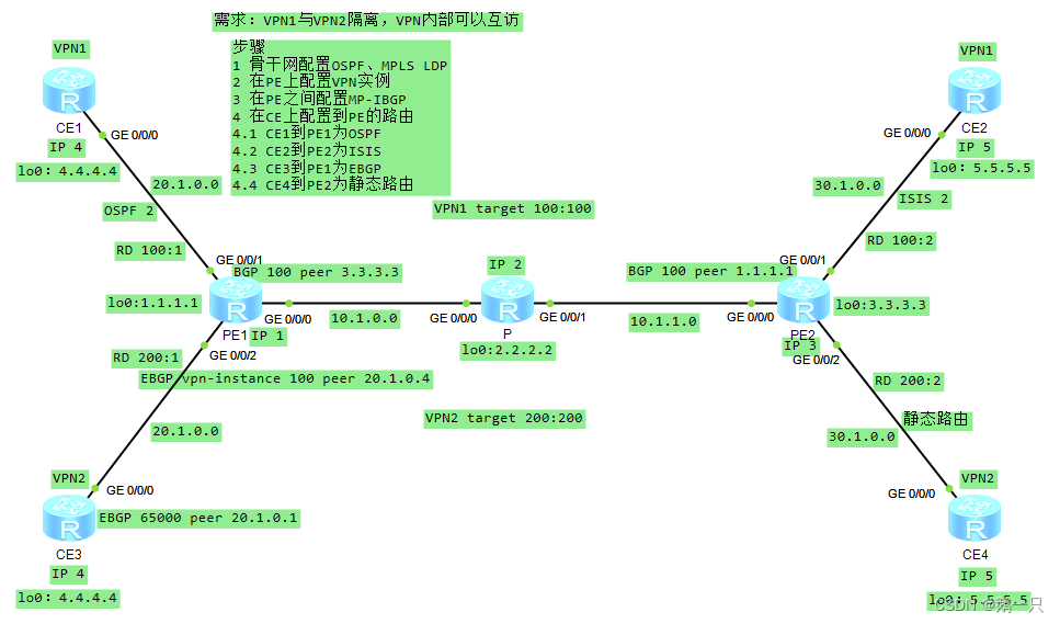
以之前的实验拓扑为例
需求:VPN1与VPN2隔离,VPN内部可以互访
CE1到PE1为OSPF
CE2到PE2为ISIS
CE3到PE1为EBGP
CE4到PE2为静态路由
PE1配置
#
 sysname PE1
#
ip vpn-instance VPN1
 ipv4-family
  route-distinguisher 100:1
  vpn-target 100:100 export-extcommunity
  vpn-target 100:100 import-extcommunity
#
ip vpn-instance VPN2
 ipv4-family
  route-distinguisher 200:1
  vpn-target 200:200 export-extcommunity
  vpn-target 200:200 import-extcommunity
#
mpls lsr-id 1.1.1.1
mpls
#
mpls ldp
#
interface GigabitEthernet0/0/0
 ip address 10.1.0.1 255.255.255.0
 ospf enable 1 area 0.0.0.0
 mpls
 mpls ldp
#
interface GigabitEthernet0/0/1
 ip binding vpn-instance VPN1
 ip address 20.1.0.1 255.255.255.0
 ospf enable 2 area 0.0.0.0            //在连接CE1的接口上开启OSPF进程2
#
interface GigabitEthernet0/0/2
 ip binding vpn-instance VPN2
 ip address 20.1.0.1 255.255.255.0
#
interface LoopBack0
 ip address 1.1.1.1 255.255.255.255
 ospf enable 1 area 0.0.0.0
#
bgp 100
 peer 3.3.3.3 as-number 100
 peer 3.3.3.3 connect-interface LoopBack0
 #
 ipv4-family unicast
  undo synchronization
  peer 3.3.3.3 enable
 #
 ipv4-family vpnv4
  policy vpn-target
  peer 3.3.3.3 enable
 #
 ipv4-family vpn-instance VPN1
  import-route ospf 2                //引入OSPF进程2路由到到BGP
 #
 ipv4-family vpn-instance VPN2
  import-route direct                      //引入直连路由到BGP
  peer 20.1.0.4 as-number 65000            //指定CE2的接口和AS号建立EBGP
#
ospf 1 router-id 1.1.1.1
 area 0.0.0.0
#
ospf 2 router-id 20.1.0.1 vpn-instance VPN1     //配置OSPF进程2绑定VPN实例
 import-route bgp type 1                        //引入BGP路由到OSPF
 area 0.0.0.0
#
PE2配置
#
 sysname PE2
#
ip vpn-instance VPN1
 ipv4-family
  route-distinguisher 100:2
  vpn-target 100:100 export-extcommunity
  vpn-target 100:100 import-extcommunity
#
ip vpn-instance VPN2
 ipv4-family
  route-distinguisher 200:2
  vpn-target 200:200 export-extcommunity
  vpn-target 200:200 import-extcommunity
#
mpls lsr-id 3.3.3.3
mpls
#
mpls ldp
#
isis 2 vpn-instance VPN1                     //配置ISIS进程2并绑定VPN实例
 is-level level-2
 cost-style wide
 network-entity 49.0001.0000.0003.00
 import-route bgp                            //引入BGP路由到ISIS进程2
#
interface GigabitEthernet0/0/0
 ip address 10.1.1.3 255.255.255.0
 ospf enable 1 area 0.0.0.0
 mpls
 mpls ldp
#
interface GigabitEthernet0/0/1
 ip binding vpn-instance VPN1
 ip address 30.1.0.3 255.255.255.0
 isis enable 2                              //在连接CE2的接口上开启ISIS进程2
#
interface GigabitEthernet0/0/2
 ip binding vpn-instance VPN2
 ip address 30.1.0.3 255.255.255.0
#
interface LoopBack0
 ip address 3.3.3.3 255.255.255.255
 ospf enable 1 area 0.0.0.0
#
bgp 100
 peer 1.1.1.1 as-number 100
 peer 1.1.1.1 connect-interface LoopBack0
 #
 ipv4-family unicast
  undo synchronization
  import-route static
  peer 1.1.1.1 enable
 #
 ipv4-family vpnv4
  policy vpn-target
  peer 1.1.1.1 enable
 #
 ipv4-family vpn-instance VPN1
  import-route isis 2                     //将ISIS路由引入到BGP的VPN实例中
 #
 ipv4-family vpn-instance VPN2
  import-route direct                     //引入直连路由到BGP
  import-route static                     //引入静态路由到BGP
#
ospf 1 router-id 3.3.3.3
 area 0.0.0.0
#
//配置VPN实例下的静态路由到CE4
ip route-static vpn-instance VPN2 5.5.5.5 255.255.255.255 30.1.0.5
#
P配置
#
 sysname P
#
mpls lsr-id 2.2.2.2
mpls
#
mpls ldp
#
interface GigabitEthernet0/0/0
 ip address 10.1.0.2 255.255.255.0
 mpls
 mpls ldp
#
interface GigabitEthernet0/0/1
 ip address 10.1.1.2 255.255.255.0
 mpls
 mpls ldp
#
interface LoopBack0
 ip address 2.2.2.2 255.255.255.255
#
ospf 1
 area 0.0.0.0
  network 0.0.0.0 255.255.255.255
#
CE1配置
#
 sysname CE1
#
interface GigabitEthernet0/0/0
 ip address 20.1.0.4 255.255.255.0
 ospf enable 2 area 0.0.0.0
#
interface LoopBack0
 ip address 4.4.4.4 255.255.255.255
 ospf enable 2 area 0.0.0.0
#
ospf 2 router-id 4.4.4.4               //CE1配置OSPF协议
 area 0.0.0.0
#
CE2配置
#
 sysname CE2
#
isis 2                                    //CE2配置ISIS协议
 cost-style wide
 network-entity 49.0001.0000.0005.00
#
firewall zone Local
 priority 15
#
interface GigabitEthernet0/0/0
 ip address 30.1.0.5 255.255.255.0
 isis enable 2
#
interface LoopBack0
 ip address 5.5.5.5 255.255.255.255
 isis enable 2
#
CE3配置
#
 sysname CE3
#
interface GigabitEthernet0/0/0
 ip address 20.1.0.4 255.255.255.0
#
interface LoopBack0
 ip address 4.4.4.4 255.255.255.255
#
bgp 65000                              //CE3配置EBGP协议
 peer 20.1.0.1 as-number 100
 #
 ipv4-family unicast
  undo synchronization
  import-route direct
  peer 20.1.0.1 enable
#
CE4配置
#
 sysname CE4
#
interface GigabitEthernet0/0/0
 ip address 30.1.0.5 255.255.255.0
#
interface LoopBack0
 ip address 5.5.5.5 255.255.255.255
#
ip route-static 0.0.0.0 0.0.0.0 GigabitEthernet0/0/0 30.1.0.3  //CE4配置静态路由协议
#
验证:查看CE路由表
<CE1>display ip routing-table
Route Flags: R - relay, D - download to fib
------------------------------------------------------------------------------
Routing Tables: Public
         Destinations : 10       Routes : 10

Destination/Mask    Proto   Pre  Cost      Flags NextHop         Interface

        4.4.4.4/32  Direct  0    0           D   127.0.0.1       LoopBack0
        5.5.5.5/32  O_ASE   150  11          D   20.1.0.1        GigabitEthernet
0/0/0
       20.1.0.0/24  Direct  0    0           D   20.1.0.4        GigabitEthernet
0/0/0
       20.1.0.4/32  Direct  0    0           D   127.0.0.1       GigabitEthernet
0/0/0
     20.1.0.255/32  Direct  0    0           D   127.0.0.1       GigabitEthernet
0/0/0
       30.1.0.0/24  O_ASE   150  2           D   20.1.0.1        GigabitEthernet
0/0/0
      127.0.0.0/8   Direct  0    0           D   127.0.0.1       InLoopBack0
      127.0.0.1/32  Direct  0    0           D   127.0.0.1       InLoopBack0
127.255.255.255/32  Direct  0    0           D   127.0.0.1       InLoopBack0
255.255.255.255/32  Direct  0    0           D   127.0.0.1       InLoopBack0


<CE2>display ip routing-table
Route Flags: R - relay, D - download to fib
------------------------------------------------------------------------------
Routing Tables: Public
         Destinations : 10       Routes : 10

Destination/Mask    Proto   Pre  Cost      Flags NextHop         Interface

        4.4.4.4/32  ISIS-L2 15   10          D   30.1.0.3        GigabitEthernet
0/0/0
        5.5.5.5/32  Direct  0    0           D   127.0.0.1       LoopBack0
       20.1.0.0/24  ISIS-L2 15   10          D   30.1.0.3        GigabitEthernet
0/0/0
       30.1.0.0/24  Direct  0    0           D   30.1.0.5        GigabitEthernet
0/0/0
       30.1.0.5/32  Direct  0    0           D   127.0.0.1       GigabitEthernet
0/0/0
     30.1.0.255/32  Direct  0    0           D   127.0.0.1       GigabitEthernet
0/0/0
      127.0.0.0/8   Direct  0    0           D   127.0.0.1       InLoopBack0
      127.0.0.1/32  Direct  0    0           D   127.0.0.1       InLoopBack0
127.255.255.255/32  Direct  0    0           D   127.0.0.1       InLoopBack0
255.255.255.255/32  Direct  0    0           D   127.0.0.1       InLoopBack0


<CE3>display ip routing-table
Route Flags: R - relay, D - download to fib
------------------------------------------------------------------------------
Routing Tables: Public
         Destinations : 10       Routes : 10

Destination/Mask    Proto   Pre  Cost      Flags NextHop         Interface

        4.4.4.4/32  Direct  0    0           D   127.0.0.1       LoopBack0
        5.5.5.5/32  EBGP    255  0           D   20.1.0.1        GigabitEthernet
0/0/0
       20.1.0.0/24  Direct  0    0           D   20.1.0.4        GigabitEthernet
0/0/0
       20.1.0.4/32  Direct  0    0           D   127.0.0.1       GigabitEthernet
0/0/0
     20.1.0.255/32  Direct  0    0           D   127.0.0.1       GigabitEthernet
0/0/0
       30.1.0.0/24  EBGP    255  0           D   20.1.0.1        GigabitEthernet
0/0/0
      127.0.0.0/8   Direct  0    0           D   127.0.0.1       InLoopBack0
      127.0.0.1/32  Direct  0    0           D   127.0.0.1       InLoopBack0
127.255.255.255/32  Direct  0    0           D   127.0.0.1       InLoopBack0
255.255.255.255/32  Direct  0    0           D   127.0.0.1       InLoopBack0


<CE4>display ip routing-table
Route Flags: R - relay, D - download to fib
------------------------------------------------------------------------------
Routing Tables: Public
         Destinations : 9        Routes : 9

Destination/Mask    Proto   Pre  Cost      Flags NextHop         Interface

        0.0.0.0/0   Static  60   0           D   30.1.0.3        GigabitEthernet
0/0/0
        5.5.5.5/32  Direct  0    0           D   127.0.0.1       LoopBack0
       30.1.0.0/24  Direct  0    0           D   30.1.0.5        GigabitEthernet
0/0/0
       30.1.0.5/32  Direct  0    0           D   127.0.0.1       GigabitEthernet
0/0/0
     30.1.0.255/32  Direct  0    0           D   127.0.0.1       GigabitEthernet
0/0/0
      127.0.0.0/8   Direct  0    0           D   127.0.0.1       InLoopBack0
      127.0.0.1/32  Direct  0    0           D   127.0.0.1       InLoopBack0
127.255.255.255/32  Direct  0    0           D   127.0.0.1       InLoopBack0
255.255.255.255/32  Direct  0    0           D   127.0.0.1       InLoopBack0
在各CE上都有到达对端的路由以及相应的协议。
特殊场景下的BGP配置
AS号替换
在MPLS VPN场景中,若PE与CE之间运行EBGP交互路由信息,则可能会出现两个站点的AS号相同的情况。

若CE1通过EBGP向PE1发送一条私网路由,并经过PE2发送到CE2,则CE2会由于AS号重复丢弃这条路由,导致属于同一VPN的Site 1和Site 2之间无法连通。
可以在PE上执行peer substitute-as命令使能AS号替换功能,即PE用本地AS号替换收到的私网路由中CE所在VPN站点的AS号,这样对端CE就不会因为AS号重复而丢弃路由了。
相关命令
AS号替换
[PE1-bgp-VPN1]peer 30.1.0.5 substitute-as SoO
在CE多归属场景,若使能了BGP的AS号替换功能,可能会引起路由环路,需要SoO(Site of Origin)特性来避免环路。
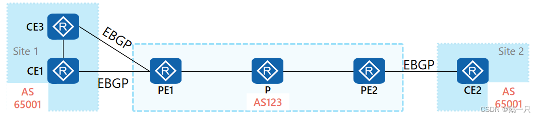
CE1与CE3处于同一个VPN站点1,CE2位于站点Site2,Site1和Site2站点所在的AS号都为65001。PE与CE之间运行的都是EBGP路由协议,为了Site 1和Site 2之间的路由可以正常学习,需要在PE1和PE2上配置AS号替换功能。
CE1传递站点内的路由给PE1,PE1传递该路由给CE3,由于配置AS号替换,CE3会接收该路由,可能会导致产生路由环路。
配置了BGP邻居的SoO后: 接收到该邻居的BGP路由时,会在路径属性中携带该SoO属性并通告给其他BGP邻居。 向该邻居通告BGP路由时,会检查路由中的SoO属性是否与配置的SoO值相同,若相同则不通告,避免引起环路。
相关命令
配置SoO属性
[PE1-bgp-VPN1]peer 30.1.0.5 soo 200:1
[PE1-bgp-VPN1]peer 30.1.1.6 soo 200:1
Hub&Spoke组网
上面演示了Intranet组网,在配置上是通过配置单个RT来实现。
而Extranet则是在同个VPN实例下配置多个RT来实现。

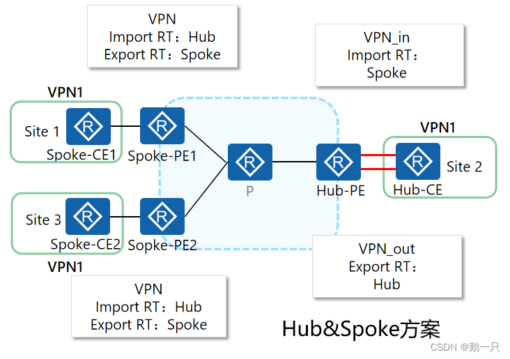
当采用Hub&Spoke方案时,可以将多个站点中的一个站点设置为Hub(中心)站点,其余站点为Spoke(辐射)站点。站点间的互访必须通过Hub站点,通过Hub站点集中管控站点间的数据传输。
Hub&Spoke特性
Spoke站点需要把路由发布给Hub站点,再通过Hub站点发布给其他Spoke站点。Spoke站点之间不直接交互路由信息。
Spoke-PE需要设置Export Target为“Spoke”,Import Target为“Hub”;
Hub-PE上需要使用两个接口或子接口(创建两个VPN实例),一个用于接收Spoke-PE发来的路由,其VPN实例的Import Target为“Spoke”;另一个用于向Spoke-PE发布路由,其VPN实例的Export Target为“Hub”。
Hub&Spoke组网方案
1:Hub-CE与Hub-PE,Spoke-PE与Spoke-CE使用EBGP
2:Hub-CE与Hub-PE,Spoke-PE与Spoke-CE使用IGP
3:Hub-CE与Hub-PE使用EBGP,Spoke-PE与Spoke-CE使用IGP
配置举例:CE与PE都使用EBGP
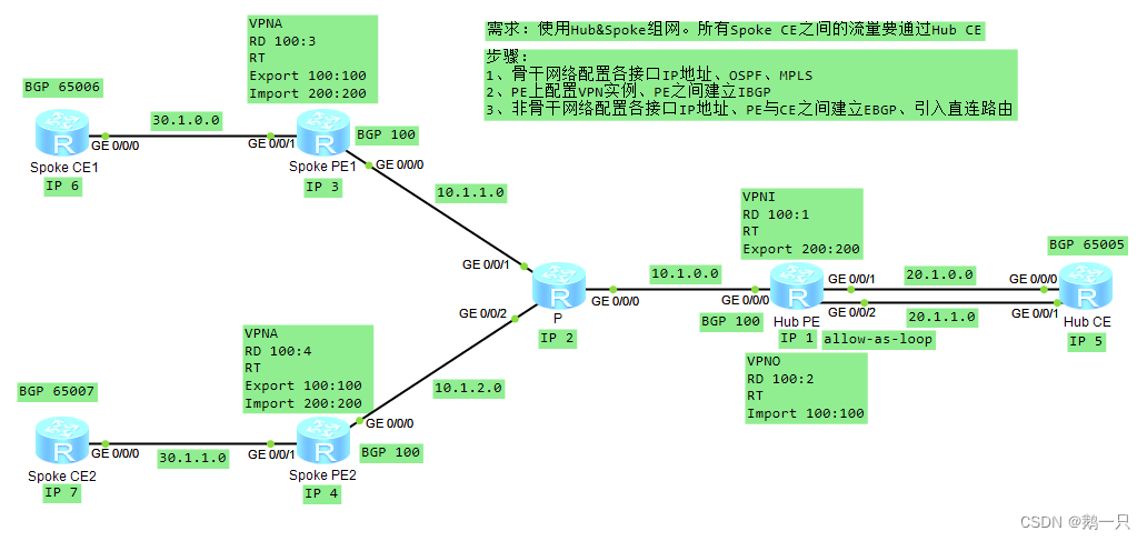
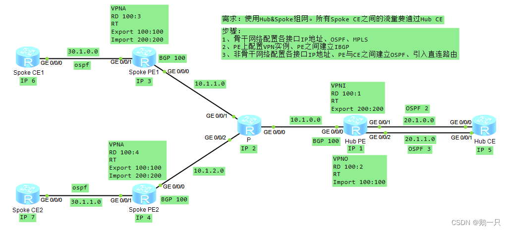
需求:使用Hub&Spoke组网。所有Spoke CE之间的流量要通过Hub CE。
步骤:
1、骨干网络配置各接口IP地址、OSPF、MPLS
2、PE上配置VPN实例、PE之间建立IBGP
3、非骨干网络配置各接口IP地址、PE与CE之间建立EBGP、引入直连路由
Spoke CE1配置
#
 sysname Spoke CE1
#
interface GigabitEthernet0/0/0
 ip address 30.1.0.6 255.255.255.0
#
interface LoopBack0
 ip address 6.6.6.6 255.255.255.255
#
bgp 65006                          //配置与Spoke PE1之间的EBGP
 peer 30.1.0.3 as-number 100
 #
 ipv4-family unicast
  undo synchronization
  import-route direct
  peer 30.1.0.3 enable
#
Spoke PE1配置
#
 sysname Spoke PE1
#
ip vpn-instance VPNA
 ipv4-family
  route-distinguisher 100:3
  vpn-target 100:100 export-extcommunity          //配置不同的进出RT
  vpn-target 200:200 import-extcommunity
#
mpls lsr-id 3.3.3.3
mpls
#
mpls ldp
#
interface GigabitEthernet0/0/0
 ip address 10.1.1.3 255.255.255.0
 ospf enable 1 area 0.0.0.0
 mpls
 mpls ldp
#
interface GigabitEthernet0/0/1
 ip binding vpn-instance VPNA
 ip address 30.1.0.3 255.255.255.0
#
interface LoopBack0
 ip address 3.3.3.3 255.255.255.255
 ospf enable 1 area 0.0.0.0
#
bgp 100
 peer 1.1.1.1 as-number 100
 peer 1.1.1.1 connect-interface LoopBack0
 #
 ipv4-family unicast
  undo synchronization
  peer 1.1.1.1 enable
 #
 ipv4-family vpnv4
  policy vpn-target
  peer 1.1.1.1 enable
 #
 ipv4-family vpn-instance VPNA
  import-route direct
  peer 30.1.0.6 as-number 65006             //配置与Spoke CE1之间的EBGP
#
ospf 1 router-id 3.3.3.3
 area 0.0.0.0
#
P配置
#
 sysname P
#
mpls lsr-id 2.2.2.2
mpls
#
mpls ldp
#
interface GigabitEthernet0/0/0
 ip address 10.1.0.2 255.255.255.0
 mpls
 mpls ldp
#
interface GigabitEthernet0/0/1
 ip address 10.1.1.2 255.255.255.0
 mpls
 mpls ldp
#
interface GigabitEthernet0/0/2
 ip address 10.1.2.2 255.255.255.0
 mpls
 mpls ldp
#
interface LoopBack0
 ip address 2.2.2.2 255.255.255.255
#
ospf 1 router-id 2.2.2.2
 area 0.0.0.0
  network 0.0.0.0 255.255.255.255
#
Hub PE配置
#
 sysname Hub PE
#
ip vpn-instance VPNI                          //配置入方向的VPN实例
 ipv4-family
  route-distinguisher 100:1
  vpn-target 100:100 import-extcommunity     //使用与Spoke CE不同的方向RT方向
#
ip vpn-instance VPNO                         //配置出方向的VPN实例
 ipv4-family
  route-distinguisher 100:2
  vpn-target 200:200 export-extcommunity     //使用与Spoke CE不同的方向RT方向
#
mpls lsr-id 1.1.1.1
mpls
#
mpls ldp
#
interface GigabitEthernet0/0/0
 ip address 10.1.0.1 255.255.255.0
 ospf enable 1 area 0.0.0.0
 mpls
 mpls ldp
#
interface GigabitEthernet0/0/1
 ip binding vpn-instance VPNI
 ip address 20.1.0.1 255.255.255.0
#
interface GigabitEthernet0/0/2
 ip binding vpn-instance VPNO
 ip address 20.1.1.1 255.255.255.0
#
interface LoopBack0
 ip address 1.1.1.1 255.255.255.255
 ospf enable 1 area 0.0.0.0
#
bgp 100
 peer 3.3.3.3 as-number 100
 peer 3.3.3.3 connect-interface LoopBack0
 peer 4.4.4.4 as-number 100
 peer 4.4.4.4 connect-interface LoopBack0
 #
 ipv4-family unicast
  undo synchronization
  peer 3.3.3.3 enable
  peer 4.4.4.4 enable
 #
 ipv4-family vpnv4
  policy vpn-target
  peer 3.3.3.3 enable
  peer 4.4.4.4 enable
 #
 ipv4-family vpn-instance VPNI          //配置与Hub CE之间的BGP,有两个方向
  import-route direct
  peer 20.1.0.5 as-number 65005
 #
 ipv4-family vpn-instance VPNO
  import-route direct
  peer 20.1.1.5 as-number 65005
  peer 20.1.1.5 allow-as-loop          //在出方向上的BGP实例下允许本地AS编号重复
#
ospf 1 router-id 1.1.1.1
 area 0.0.0.0
#
Hub CE配置
#
 sysname Hub CE
#
interface GigabitEthernet0/0/0
 ip address 20.1.0.5 255.255.255.0
#
interface GigabitEthernet0/0/1
 ip address 20.1.1.5 255.255.255.0
#
interface LoopBack0
 ip address 5.5.5.5 255.255.255.255
#
bgp 65005                             //配置与Hub PE之间的BGP
 peer 20.1.0.1 as-number 100
 peer 20.1.1.1 as-number 100
 #
 ipv4-family unicast
  undo synchronization
  import-route direct
  peer 20.1.0.1 enable
  peer 20.1.1.1 enable
#
Spoke PE2配置
#
 sysname Spoke PE2
#
ip vpn-instance VPNA
 ipv4-family
  route-distinguisher 100:4
  vpn-target 100:100 export-extcommunity     //配置不同的RT,同Spoke PE1
  vpn-target 200:200 import-extcommunity
#
mpls lsr-id 4.4.4.4
mpls
#
mpls ldp
#
interface GigabitEthernet0/0/0
 ip address 10.1.2.4 255.255.255.0
 ospf enable 1 area 0.0.0.0
 mpls
 mpls ldp
#
interface GigabitEthernet0/0/1
 ip binding vpn-instance VPNA
 ip address 30.1.1.4 255.255.255.0
#
interface LoopBack0
 ip address 4.4.4.4 255.255.255.255
 ospf enable 1 area 0.0.0.0
#
bgp 100
 peer 1.1.1.1 as-number 100
 peer 1.1.1.1 connect-interface LoopBack0
 #
 ipv4-family unicast
  undo synchronization
  peer 1.1.1.1 enable
 #
 ipv4-family vpnv4
  policy vpn-target
  peer 1.1.1.1 enable
 #
 ipv4-family vpn-instance VPNA
  import-route direct
  peer 30.1.1.7 as-number 65007        //配置与Spoke CE2之间的EBGP
#
ospf 1 router-id 4.4.4.4
 area 0.0.0.0
#
Spoke CE2配置
#
 sysname Spoke CE2
#
interface GigabitEthernet0/0/0
 ip address 30.1.1.7 255.255.255.0
#
interface LoopBack0
 ip address 7.7.7.7 255.255.255.255
#
bgp 65007                            //配置与Spoke PE2之间的EBGP
 peer 30.1.1.4 as-number 100
 #
 ipv4-family unicast
  undo synchronization
  import-route direct
  peer 30.1.1.4 enable
#
测试Spoke CE之间的通信
<Spoke CE1>ping 7.7.7.7
  PING 7.7.7.7: 56  data bytes, press CTRL_C to break
    Reply from 7.7.7.7: bytes=56 Sequence=1 ttl=248 time=80 ms
    Reply from 7.7.7.7: bytes=56 Sequence=2 ttl=248 time=90 ms
    Reply from 7.7.7.7: bytes=56 Sequence=3 ttl=248 time=70 ms
    Reply from 7.7.7.7: bytes=56 Sequence=4 ttl=248 time=60 ms
    Reply from 7.7.7.7: bytes=56 Sequence=5 ttl=248 time=60 ms

  --- 7.7.7.7 ping statistics ---
    5 packet(s) transmitted
    5 packet(s) received
    0.00% packet loss
    round-trip min/avg/max = 60/72/90 ms
测试成功。
配置举例:Hub-CE与Hub-PE使用EBGP,Spoke-PE与Spoke-CE使用OSPF
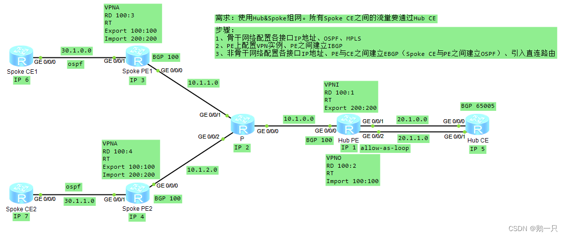 以前面的实验为例,但是在Spoke-PE与Spoke-CE之间采用OSPF交换路由,Hub-CE与Hub-PE依旧使用EBGP
Spoke CE1配置(CE2同)
#
 sysname Spoke CE1
#
interface GigabitEthernet0/0/0
 ip address 30.1.0.6 255.255.255.0
#
interface LoopBack0
 ip address 6.6.6.6 255.255.255.255
#
ospf 1 router-id 6.6.6.6               //与Spoke PE1之间建立OSPF
 area 0.0.0.0
  network 0.0.0.0 255.255.255.255
#
Spoke PE1配置(PE2同)
#
 sysname Spoke PE1
#
ip vpn-instance VPNA
 ipv4-family
  route-distinguisher 100:3
  vpn-target 100:100 export-extcommunity
  vpn-target 200:200 import-extcommunity
#
mpls lsr-id 3.3.3.3
mpls
#
mpls ldp
#
interface GigabitEthernet0/0/0
 ip address 10.1.1.3 255.255.255.0
 ospf enable 1 area 0.0.0.0
 mpls
 mpls ldp
#
interface GigabitEthernet0/0/1
 ip binding vpn-instance VPNA
 ip address 30.1.0.3 255.255.255.0
 ospf enable 2 area 0.0.0.0                    //与CE1直连接口开启OSPF进程2
#
interface LoopBack0
 ip address 3.3.3.3 255.255.255.255
 ospf enable 1 area 0.0.0.0
#
bgp 100
 peer 1.1.1.1 as-number 100
 peer 1.1.1.1 connect-interface LoopBack0
 #
 ipv4-family unicast
  undo synchronization
  peer 1.1.1.1 enable
 #
 ipv4-family vpnv4
  policy vpn-target
  peer 1.1.1.1 enable
 #
 ipv4-family vpn-instance VPNA
  import-route ospf 2                        //在BGP中的VPN实例下引入OSPF进程2
#
ospf 1 router-id 3.3.3.3
 area 0.0.0.0
#
ospf 2 router-id 3.3.3.3 vpn-instance VPNA   //开启OSPF进程2并绑定VPN实例
 import-route bgp type 1                     //在OSPF进程2下引入BGP路由
 area 0.0.0.0
#
测试Spoke CE之间的通信
<Spoke CE1>ping 7.7.7.7
  PING 7.7.7.7: 56  data bytes, press CTRL_C to break
    Reply from 7.7.7.7: bytes=56 Sequence=1 ttl=248 time=80 ms
    Reply from 7.7.7.7: bytes=56 Sequence=2 ttl=248 time=80 ms
    Reply from 7.7.7.7: bytes=56 Sequence=3 ttl=248 time=60 ms
    Reply from 7.7.7.7: bytes=56 Sequence=4 ttl=248 time=70 ms
    Reply from 7.7.7.7: bytes=56 Sequence=5 ttl=248 time=60 ms

  --- 7.7.7.7 ping statistics ---
    5 packet(s) transmitted
    5 packet(s) received
    0.00% packet loss
    round-trip min/avg/max = 60/70/80 ms
测试成功
配置举例:CE与PE都使用OSPF
以前面的实验为例,在Hub-CE与Hub-PE之间的路由交换也采用OSPF
Hub CE配置
#
 sysname Hub CE
#
interface GigabitEthernet0/0/0
 ip address 20.1.0.5 255.255.255.0
 ospf enable 2 area 0.0.0.0            //在入方向的接口开启OSPF进程2
#
interface GigabitEthernet0/0/1
 ip address 20.1.1.5 255.255.255.0
 ospf enable 3 area 0.0.0.0            //在出方向的接口开启OSPF进程3
#
interface LoopBack0
 ip address 5.5.5.5 255.255.255.255
 ospf enable 2 area 0.0.0.0            //将环回口(代表私网路由)开启入方向的OSPF进程
#
ospf 2 router-id 5.5.5.5               //开启OSPF进程2
 area 0.0.0.0
#
ospf 3 router-id 5.5.5.5               //开启OSPF进程3
 import-route ospf 2                   //引入OSPF进程2路由
 area 0.0.0.0
#
Hub PE配置
#
 sysname Hub PE
#
ip vpn-instance VPNI
 ipv4-family
  route-distinguisher 100:1
  vpn-target 100:100 import-extcommunity
#
ip vpn-instance VPNO
 ipv4-family
  route-distinguisher 100:2
  vpn-target 200:200 export-extcommunity
#
mpls lsr-id 1.1.1.1
mpls
#
mpls ldp
#
interface GigabitEthernet0/0/0
 ip address 10.1.0.1 255.255.255.0
 ospf enable 1 area 0.0.0.0
 mpls
 mpls ldp
#
interface GigabitEthernet0/0/1
 ip binding vpn-instance VPNI
 ip address 20.1.0.1 255.255.255.0
 ospf enable 2 area 0.0.0.0                //入方向的接口开启OSPF进程2
#
interface GigabitEthernet0/0/2
 ip binding vpn-instance VPNO
 ip address 20.1.1.1 255.255.255.0
 ospf enable 3 area 0.0.0.0                //出方向的接口开启OSPF进程3
#
interface LoopBack0
 ip address 1.1.1.1 255.255.255.255
 ospf enable 1 area 0.0.0.0
#
bgp 100
 peer 3.3.3.3 as-number 100
 peer 3.3.3.3 connect-interface LoopBack0
 peer 4.4.4.4 as-number 100
 peer 4.4.4.4 connect-interface LoopBack0
 #
 ipv4-family unicast
  undo synchronization
  peer 3.3.3.3 enable
  peer 4.4.4.4 enable
 #
 ipv4-family vpnv4
  policy vpn-target
  peer 3.3.3.3 enable
  peer 4.4.4.4 enable
 #
 ipv4-family vpn-instance VPNO
  import-route ospf 3                         //在IBGP中引入Hub CE过来的ospf路由
#
ospf 1 router-id 1.1.1.1
 area 0.0.0.0
#
ospf 2 router-id 1.1.1.1 vpn-instance VPNI    //开启OSPF进程2并绑定入方向的VPN实例
 import-route bgp type 1                      //在入方向中引入IBGP带来的对端路由
 area 0.0.0.0
#
ospf 3 router-id 1.1.1.1 vpn-instance VPNO    //开启OSPF进程3并绑定出方向的VPN实例
 area 0.0.0.0
#
测试CE之间的通信
<Spoke CE1>tracert 7.7.7.7

 traceroute to  7.7.7.7(7.7.7.7), max hops: 30 ,packet length: 40,press CTRL_C t
o break

 1 30.1.0.3 20 ms  10 ms  10 ms

 2 10.1.1.2 50 ms  20 ms  60 ms

 3 20.1.1.1 30 ms  30 ms  30 ms

 4 20.1.1.5 40 ms  30 ms  40 ms

 5 20.1.0.1 40 ms  30 ms  30 ms

 6 10.1.0.2 60 ms  50 ms  50 ms

 7 30.1.1.4 40 ms  60 ms  50 ms

 8 30.1.1.7 50 ms  70 ms  50 ms
测试成功
OSPF与BGP互操作
当PE-CE间部署OSPF交互路由信息时,若在PE上使用标准BGP/OSPF过程(简称为BGP/OSPF互操作)互来传递路由信息,则远端PE在将BGP引入VPN实例的OSPF进程时,会直接产生Type5 LSA,不同站点都会将其他站点的路由视为自治系统外部路由(AS_external)。
在实际应用中,如果两个要互通的Site都在相同的AS内,那么每个Site都应该将另一个Site的路由看成区域间路由,而不是AS外部路由。
为了解决标准BGP/OSPF的互操作导致的OSPF路由信息丢失的问题,BGP和OSPF都做了相应的拓展。
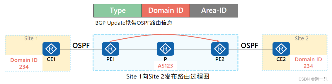
BGP扩展团体属性
为了保留OSPF的路由信息,BGP新增了部分可携带OSPF路由信息的团体属性
Domain ID:域标识符用来标识和区分不同的域。
Route Type:包含被引入到BGP的OSPF路由的 Area-ID 以及Route Type
Area-ID:PE 的VPN实例的OSPF进程与CE建立邻接关系的区域号
Route Type:被引入的 OSPF 路由的类型
1 或 2:表示路由的类型为区域内部路由, 也就是 PE 根据 Type-1 及 Type-2 LSA 所计算出来的路由。
3:表示路由的类型为区域间路由。
5:表示路由的类型为 OSPF 外部路由,也就是 PE 通过 Type-5 LSA 计算得出的路由。当 Route-Type 字段的值为 5 时, Area-ID 字段的值需为 0.0.0.0。
7:表示路由的类型为 NSSA 路由,也就是 PE 通过 Type-7 LSA 计算得出的路由。
Domain ID
在PE上将OSPF引入BGP时,PE将根据本地的配置为BGP路由增加域ID属性,域ID作为BGP的扩展团体属性传播。
在PE将BGP路由引入OSPF时,若BGP路由携带的Domain ID与本地相同,则认为两个站点属于同一个OSPF路由域。若不相同,则认为不在同一个路由域。
Domain ID需要在绑定到VRF的OSPF进程视图下使用命令domain-id配置。
缺省情况下,Domain ID的值为0(NULL)。如果不同OSPF域都使用NULL作为Domain ID,将无法区分OSPF域,因此它们之间的路由将被当作区域内路由。
如果一个OSPF域配置了非0(即非NULL)的Domain ID,NULL不再是该OSPF域的Domain ID。
建议与同一个VPN相关的所有OSPF实例都使用相同的Domain ID,或者都使用缺省的Domain ID。
Domain ID与Route Type
根据BGP路由中的Domain ID与Route Type属性,PE将产生不同类型的OSPF LSA类型发布到VRF的OSPF进程中
| Domain ID与本地是否相同 | Route Type | PE生成的OSPF LSA类型 |
| 是 | 1、2、3 | 3 |
| 5、7 | 5、7 | |
| 否 | 1、2、3、5、7 | 5、7 |
相关命令
配置Domain ID
[PE1-ospf-2]domain-id 1.1.1.1OSPF VPN防环
Type3路由防环
问题:在以上双归属场景中,由于PE1可能会同时收到CE1和PE3去往5.5.5.5的3类路由,导致环路或者网络震荡。
解决方法:根据OSPF的防环特性,关闭PE3上的3类LSA的DN位检查,使其开始计算路由,去往5.5.5.5的路由就会往CE2走。
相关命令
禁止检查3类OSPF LSA的DN位
[PE3-ospf-2]dn-bit-check disable summary Type5/7路由防环
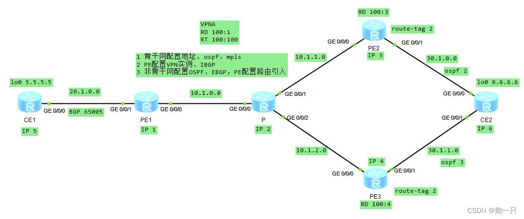
问题:在以上场景中,PE1将同时收到来自CE1与PE3去往5.5.5.5的5类路由,PE3中的路由是BGP引入的IGP(OSPF)路由,其AS_Path为空,因此PE3的路由优先级比从CE1的优先级高。从而导致环路
解决方法:在PE2和PE3上配置相同的VPN Route Tag(VPN路由标记)来防止此5类或7类路由环路。当PE收到同样Tag的LSA,对其忽略,避免上述环路。
相关命令
配置VPN的路由标记
[PE2-ospf-2]route-tag 2MCE组网
当一个私网需要根据业务或者网络划分VPN时,不同VPN用户间的业务需要完全隔离。此时,为每个VPN单独配置一台CE将增加用户的设备开支和维护成本。
具有MCE(Multi-VPN-Instance,CE多实例CE)功能的CE设备可以在MPLS VPN组网应用中承担多个VPN实例的CE功能,减少用户网络设备的投入。
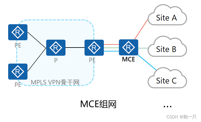
MCE将PE的部分功能扩展到CE设备,通过将不同的接口与VPN绑定,并为每个VPN创建和维护独立的路由转发表(Multi-VRF)。
MCE与对应的PE之间可以通过物理接口、子接口或者逻辑接口进行互联,PE上需要将这些接口绑定到对应的VPN实例。
在MCE设备上部署OSPF VPN多实例时,如果有Type3、Type5或Type7 LSA中设置DN Bit,就会导致这些路由无法计算,因为OSPF进行路由计算会进行防环路检测。这种情况下,通过配置vpn-instance-capability simple命令可以取消OSPF路由环路检测,不检查DN Bit和Route-tag而直接计算出所有OSPF路由,Route-tag恢复为缺省值1。
相关命令
禁止环路监测,包括DN位和Route-tag
[MCE-ospf-100] vpn-instance-capability simple配置举例:配置MCE
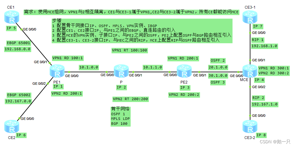
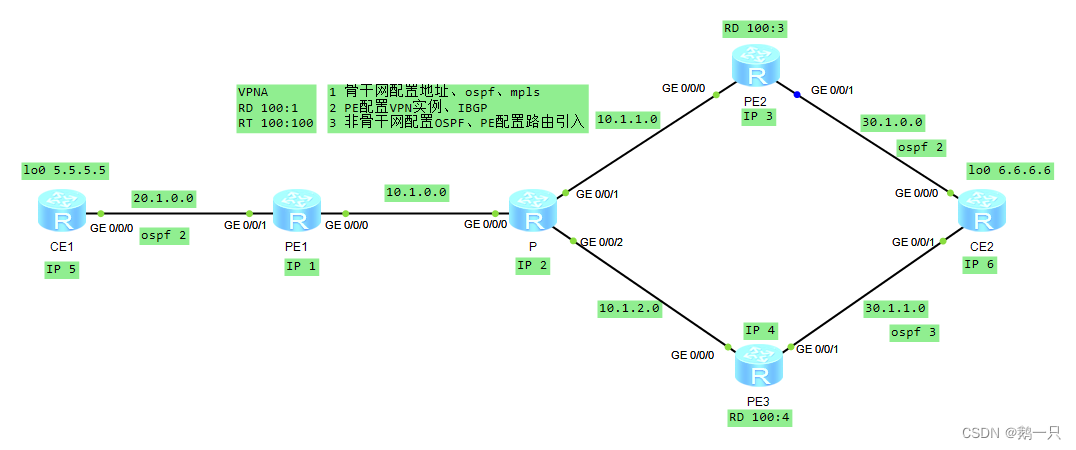
需求:使用MCE组网,VPN1与2相互隔离,CE1与CE3-1属于VPN1,CE2与CE3-2属于VPN2,所有CE都能访问MCE
步骤
1 配置骨干网接口IP、OSPF、MPLS、VPN实例、IBGP
2 配置CE1、CE2接口IP、与PE1之间的EBGP、直连路由的引入
3 配置MCE的VPN实例、子接口IP、与PE2之间的OSPF,PE2上配置OSPF与BGP路由相互引入
4 配置CE3-1、CE3-2接口IP、与MEC之间的RIP,MCE上配置RIP与OSPF路由相互引入
CE1配置
#
 sysname CE1
#
router id 5.5.5.5
#
interface GigabitEthernet0/0/0
 ip address 192.168.0.5 255.255.255.0
#
interface LoopBack0
 ip address 5.5.5.5 255.255.255.255
#
bgp 65001
 peer 192.168.0.1 as-number 100
 #
 ipv4-family unicast
  undo synchronization
  import-route direct
  peer 192.168.0.1 enable
#
CE2配置
#
 sysname CE2
#
router id 6.6.6.6
#
interface GigabitEthernet0/0/0
 ip address 192.167.0.6 255.255.255.0
#
interface LoopBack0
 ip address 6.6.6.6 255.255.255.255
#
bgp 65002
 peer 192.167.0.1 as-number 100
 #
 ipv4-family unicast
  undo synchronization
  import-route direct
  peer 192.167.0.1 enable
#
PE1配置
#
 sysname PE1
#
router id 1.1.1.1
#
ip vpn-instance VPN1
 ipv4-family
  route-distinguisher 100:1
  vpn-target 100:100 export-extcommunity
  vpn-target 100:100 import-extcommunity
#
ip vpn-instance VPN2
 ipv4-family
  route-distinguisher 200:1
  vpn-target 200:200 export-extcommunity
  vpn-target 200:200 import-extcommunity
#
mpls lsr-id 1.1.1.1
mpls
#
mpls ldp
#
interface GigabitEthernet0/0/0
 ip address 10.1.0.1 255.255.255.0
 ospf enable 1 area 0.0.0.0
 mpls
 mpls ldp
#
interface GigabitEthernet0/0/1
 ip binding vpn-instance VPN1
 ip address 192.168.0.1 255.255.255.0
#
interface GigabitEthernet0/0/2
 ip binding vpn-instance VPN2
 ip address 192.167.0.1 255.255.255.0
#
interface LoopBack0
 ip address 1.1.1.1 255.255.255.255
 ospf enable 1 area 0.0.0.0
#
bgp 100
 peer 3.3.3.3 as-number 100
 peer 3.3.3.3 connect-interface LoopBack0
 #
 ipv4-family unicast
  undo synchronization
  peer 3.3.3.3 enable
 #
 ipv4-family vpnv4
  policy vpn-target
  peer 3.3.3.3 enable
 #
 ipv4-family vpn-instance VPN1
  import-route direct
  peer 192.168.0.5 as-number 65001
 #
 ipv4-family vpn-instance VPN2
  import-route direct
  peer 192.167.0.6 as-number 65002
#
ospf 1
 area 0.0.0.0
#
P配置
#
 sysname P
#
router id 2.2.2.2
#
mpls lsr-id 2.2.2.2
mpls
#
mpls ldp
#
interface GigabitEthernet0/0/0
 ip address 10.1.0.2 255.255.255.0
 mpls
 mpls ldp
#
interface GigabitEthernet0/0/1
 ip address 10.1.1.2 255.255.255.0
 mpls
 mpls ldp
#
interface LoopBack0
 ip address 2.2.2.2 255.255.255.255
#
ospf 1
 area 0.0.0.0
  network 0.0.0.0 255.255.255.255
#
PE2配置
#
 sysname PE2
#
router id 3.3.3.3
#
ip vpn-instance VPN1
 ipv4-family
  route-distinguisher 200:1
  vpn-target 100:100 export-extcommunity
  vpn-target 100:100 import-extcommunity
#
ip vpn-instance VPN2
 ipv4-family
  route-distinguisher 200:2
  vpn-target 200:200 export-extcommunity
  vpn-target 200:200 import-extcommunity
#
mpls lsr-id 3.3.3.3
mpls
#
mpls ldp
#
interface GigabitEthernet0/0/0
 ip address 10.1.1.3 255.255.255.0
 ospf enable 1 area 0.0.0.0
 mpls
 mpls ldp
#
interface GigabitEthernet0/0/1.1
 dot1q termination vid 1
 ip binding vpn-instance VPN1
 ip address 20.1.0.3 255.255.255.0
 ospf enable 2 area 0.0.0.0
 arp broadcast enable
#
interface GigabitEthernet0/0/1.2
 dot1q termination vid 2
 ip binding vpn-instance VPN2
 ip address 30.1.0.3 255.255.255.0
 ospf enable 3 area 0.0.0.0
 arp broadcast enable
#
interface LoopBack0
 ip address 3.3.3.3 255.255.255.255
 ospf enable 1 area 0.0.0.0
#
bgp 100
 peer 1.1.1.1 as-number 100
 peer 1.1.1.1 connect-interface LoopBack0
 #
 ipv4-family unicast
  undo synchronization
  peer 1.1.1.1 enable
 #
 ipv4-family vpnv4
  policy vpn-target
  peer 1.1.1.1 enable
 #
 ipv4-family vpn-instance VPN1
  import-route ospf 2
 #
 ipv4-family vpn-instance VPN2
  import-route ospf 3
#
ospf 1
 area 0.0.0.0
#
ospf 2 vpn-instance VPN1
 import-route bgp type 1
 area 0.0.0.0
#
ospf 3 vpn-instance VPN2
 import-route bgp type 1
 area 0.0.0.0
#
MCE配置
#
 sysname MCE
#
router id 4.4.4.4
#
ip vpn-instance VPN1
 ipv4-family
  route-distinguisher 300:1
  vpn-target 100:100 export-extcommunity
  vpn-target 100:100 import-extcommunity
#
ip vpn-instance VPN2
 ipv4-family
  route-distinguisher 300:2
  vpn-target 200:200 export-extcommunity
  vpn-target 200:200 import-extcommunity
#
interface GigabitEthernet0/0/0.1
 dot1q termination vid 1
 ip binding vpn-instance VPN1
 ip address 20.1.0.4 255.255.255.0
 ospf enable 2 area 0.0.0.0
 arp broadcast enable
#
interface GigabitEthernet0/0/0.2
 dot1q termination vid 2
 ip binding vpn-instance VPN2
 ip address 30.1.0.4 255.255.255.0
 ospf enable 3 area 0.0.0.0
 arp broadcast enable
#
interface GigabitEthernet0/0/1
 ip binding vpn-instance VPN1
 ip address 192.168.1.4 255.255.255.0
#
interface GigabitEthernet0/0/2
 ip binding vpn-instance VPN2
 ip address 192.167.1.4 255.255.255.0
#
interface LoopBack0
 ip address 4.4.4.4 255.255.255.255
#
ospf 2 vpn-instance VPN1
 import-route rip 1
 vpn-instance-capability simple          \\配置禁止环路监测
 area 0.0.0.0
#
ospf 3 vpn-instance VPN2
 import-route rip 2
 vpn-instance-capability simple          \\配置禁止环路监测
 area 0.0.0.0
#
rip 1 vpn-instance VPN1
 version 2
 network 192.168.1.0
 import-route ospf 2
#
rip 2 vpn-instance VPN2
 version 2
 network 192.167.1.0
 import-route ospf 3
#
CE3-1配置
#
 sysname CE3-1
#
interface GigabitEthernet0/0/0
 ip address 192.168.1.7 255.255.255.0
#
interface LoopBack0
 ip address 7.7.7.7 255.255.255.255
#
rip 1
 version 2
 network 192.168.1.0
 network 7.0.0.0
 import-route direct
#
CE3-2配置
#
 sysname CE3-2
#
interface GigabitEthernet0/0/0
 ip address 192.167.1.8 255.255.255.0
#
interface LoopBack0
 ip address 8.8.8.8 255.255.255.255
#
rip 2
 version 2
 network 192.167.1.0
 network 8.0.0.0
 import-route direct
#
Sham link(伪连接)

如果本地CE所在网段和远端CE所在网段间存在一条区域内OSPF链路,则称之为后门链路(Backdoor link)。
经过后门链路的路由是区域内路由,其优先级要高于经过MPLS VPN骨干网的区域间路由,这将导致VPN流量总是通过后门路由转发,而不走骨干网。而后门链路一般只用作备份链路。
为了避免上述问题,可以在PE之间建立OSPF伪连接(Sham link),使经过MPLS VPN骨干网的路由也成为OSPF区域内路由,并且被优选。
OSPF伪连接(Sham link)是MPLS VPN骨干网上两个PE之间的点到点链路,这些链路使用借用(Unnumbered)的地址。
OSPF伪连接仅应用在属于同一个OSPF区域的两个Site间存在后门链路的情况,如果Site间没有后门链路,则不需要配置OSPF伪连接。
为了使VPN流量通过MPLS骨干网转发,在配置伪连接时,应保证伪连接的cost值小于通过用户网络转发时OSPF路由的cost值。因此,常常需要调整用户网络转发接口的cost值,使它比伪连接的cost值大。
相关命令
配置伪连接,并配置伪连接的参数(伪连接的源地址和目的地址使用32位掩码的Loopback接口地址,该Loopback接口需要绑定到VPN实例中)
[PE1-ospf-1-area-0.0.0.1]sham-link 1.1.1.1 3.3.3.3配置举例:配置伪连接

需求:在MPLS VPN网路上配置虚连接,确保路由优选虚连接
步骤
1 配置骨干网络,包括接口IP、OSPF 1、MPLS、IBGP
2 配置边缘网络,包括PE上的VPN实例、CE与PE的接口IP、OPPF 2,路由引入
3 配置后门连接,包括CE之间的OSPF 2、OSPF 2开销值
4 配置虚连接,包括连接PE之间的环回口、OSPF 2
PE1配置
#
 sysname PE1
#
router id 1.1.1.1
#
ip vpn-instance VPN1
 ipv4-family
  route-distinguisher 100:1
  vpn-target 100:100 export-extcommunity
  vpn-target 100:100 import-extcommunity
#
mpls lsr-id 1.1.1.1
mpls
#
mpls ldp
#
interface GigabitEthernet0/0/0
 ip address 10.1.0.1 255.255.255.0
 ospf enable 1 area 0.0.0.0
 mpls
 mpls ldp
#
interface GigabitEthernet0/0/1
 ip binding vpn-instance VPN1
 ip address 20.1.0.1 255.255.255.0
 ospf enable 2 area 0.0.0.0
#
interface LoopBack0
 ip address 1.1.1.1 255.255.255.255
 ospf enable 1 area 0.0.0.0
#
interface LoopBack1
 ip binding vpn-instance VPN1
 ip address 11.1.1.1 255.255.255.255
 ospf enable 2 area 0.0.0.0
#
bgp 100
 peer 3.3.3.3 as-number 100
 peer 3.3.3.3 connect-interface LoopBack0
 #
 ipv4-family unicast
  undo synchronization
  peer 3.3.3.3 enable
 #
 ipv4-family vpnv4
  policy vpn-target
  peer 3.3.3.3 enable
 #
 ipv4-family vpn-instance VPN1
  import-route direct
  import-route ospf 2
#
ospf 1 router-id 1.1.1.1
 area 0.0.0.0
#
ospf 2 router-id 3.3.3.3 vpn-instance VPN1
 import-route bgp
 area 0.0.0.0
  sham-link 11.1.1.1 33.3.3.3                  //与PE2建立伪连接
#
P配置
#
 sysname P
#
router id 2.2.2.2
#
mpls lsr-id 2.2.2.2
mpls
#
mpls ldp
#
interface GigabitEthernet0/0/0
 ip address 10.1.0.2 255.255.255.0
 ospf enable 1 area 0.0.0.0
 mpls
 mpls ldp
#
interface GigabitEthernet0/0/1
 ip address 10.1.1.2 255.255.255.0
 ospf enable 1 area 0.0.0.0
 mpls
 mpls ldp
#
interface LoopBack0
 ip address 2.2.2.2 255.255.255.255
 ospf enable 1 area 0.0.0.0
#
ospf 1 router-id 2.2.2.2
 area 0.0.0.0
#
PE2配置
#
 sysname PE2
#
router id 3.3.3.3
#
ip vpn-instance VPN1
 ipv4-family
  route-distinguisher 100:3
  vpn-target 100:100 export-extcommunity
  vpn-target 100:100 import-extcommunity
#
mpls lsr-id 3.3.3.3
mpls
#
mpls ldp
#
interface GigabitEthernet0/0/0
 ip address 10.1.1.3 255.255.255.0
 ospf enable 1 area 0.0.0.0
 mpls
 mpls ldp
#
interface GigabitEthernet0/0/1
 ip binding vpn-instance VPN1
 ip address 30.1.0.3 255.255.255.0
 ospf enable 2 area 0.0.0.0
#
interface LoopBack0
 ip address 3.3.3.3 255.255.255.255
 ospf enable 1 area 0.0.0.0
#
interface LoopBack1
 ip binding vpn-instance VPN1
 ip address 33.3.3.3 255.255.255.255
 ospf enable 2 area 0.0.0.0
#
bgp 100
 peer 1.1.1.1 as-number 100
 peer 1.1.1.1 connect-interface LoopBack0
 #
 ipv4-family unicast
  undo synchronization
  peer 1.1.1.1 enable
 #
 ipv4-family vpnv4
  policy vpn-target
  peer 1.1.1.1 enable
 #
 ipv4-family vpn-instance VPN1
  import-route direct
  import-route ospf 2
#
ospf 1 router-id 3.3.3.3
 area 0.0.0.0
#
ospf 2 router-id 3.3.3.3 vpn-instance VPN1
 import-route bgp
 area 0.0.0.0
  sham-link 33.3.3.3 11.1.1.1               //与PE1建立伪连接
#
CE1配置
#
 sysname CE1
#
router id 4.4.4.4
#
interface GigabitEthernet0/0/0
 ip address 20.1.0.4 255.255.255.0
#
interface GigabitEthernet0/0/1
 ip address 40.1.0.4 255.255.255.0
 ospf cost 10                         //修改(改大)后门连接的开销值
#
interface LoopBack0
 ip address 4.4.4.4 255.255.255.255
#
ospf 2 router-id 4.4.4.4
 area 0.0.0.0
  network 0.0.0.0 255.255.255.255
#
CE2配置
#
 sysname CE2
#
router id 5.5.5.5
#
interface GigabitEthernet0/0/0
 ip address 30.1.0.5 255.255.255.0
#
interface GigabitEthernet0/0/1
 ip address 40.1.0.5 255.255.255.0
 ospf cost 10                         //修改(改大)后门连接的开销值
#
interface LoopBack0
 ip address 5.5.5.5 255.255.255.255
#
ospf 2 router-id 5.5.5.5
 area 0.0.0.0
  network 0.0.0.0 255.255.255.255
#
查看CE1的路由表
<CE1>display ip routing-table
Route Flags: R - relay, D - download to fib
------------------------------------------------------------------------------
Routing Tables: Public
         Destinations : 15       Routes : 15

Destination/Mask    Proto   Pre  Cost      Flags NextHop         Interface

        4.4.4.4/32  Direct  0    0           D   127.0.0.1       LoopBack0
        5.5.5.5/32  OSPF    10   3           D   20.1.0.1        GigabitEthernet
0/0/0
       11.1.1.1/32  OSPF    10   1           D   20.1.0.1        GigabitEthernet
0/0/0
       20.1.0.0/24  Direct  0    0           D   20.1.0.4        GigabitEthernet
0/0/0
       20.1.0.4/32  Direct  0    0           D   127.0.0.1       GigabitEthernet
0/0/0
     20.1.0.255/32  Direct  0    0           D   127.0.0.1       GigabitEthernet
0/0/0
       30.1.0.0/24  OSPF    10   3           D   20.1.0.1        GigabitEthernet
0/0/0
       33.3.3.3/32  OSPF    10   2           D   20.1.0.1        GigabitEthernet
0/0/0
       40.1.0.0/24  Direct  0    0           D   40.1.0.4        GigabitEthernet
0/0/1
       40.1.0.4/32  Direct  0    0           D   127.0.0.1       GigabitEthernet
0/0/1
     40.1.0.255/32  Direct  0    0           D   127.0.0.1       GigabitEthernet
0/0/1
      127.0.0.0/8   Direct  0    0           D   127.0.0.1       InLoopBack0
      127.0.0.1/32  Direct  0    0           D   127.0.0.1       InLoopBack0
127.255.255.255/32  Direct  0    0           D   127.0.0.1       InLoopBack0
255.255.255.255/32  Direct  0    0           D   127.0.0.1       InLoopBack0
通往CE2的路由(5.5.5.5)的开销为3,下一跳为PE1,配置成功。
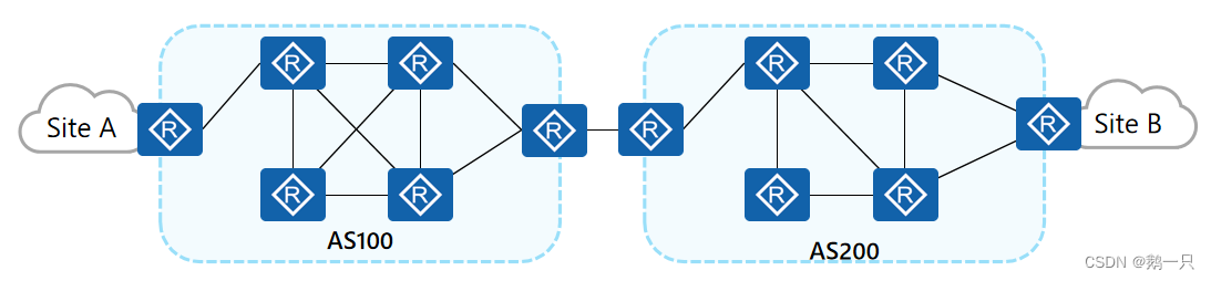
MPLS VPN跨域组网
随着MPLS VPN解决方案的广泛应用,服务的终端用户的规格和范围也在增长,在一个企业内部的站点数目越来越大,某个地理位置与另外一个服务提供商相连的需求变得非常的普遍,例如国内运营商的不同城域网之间,或相互协作的运营商的骨干网之间都存在着跨越不同自治系统(AS,Autonomous System)的情况。
一般的MPLS VPN体系结构都是在一个AS内运行,任何VPN的路由信息都是只能在一个AS内按需扩散。AS之间的MPLS VPN部署需要通过跨域(Inter-AS) MPLS VPN解决方案来实现。
RFC2547中提出了三种跨域VPN解决方案
1 跨域VPN-OptionA(Inter-Provider Backbones Option A)方式:需要跨域的VPN在ASBR(AS Boundary Router)间通过专用的接口管理自己的VPN路由,也称为VRF-to-VRF;
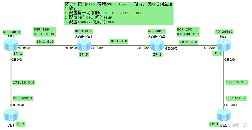
2 跨域VPN-OptionB(Inter-Provider Backbones Option B)方式:ASBR间通过MP-EBGP发布标签VPN-IPv4路由,也称为EBGP redistribution of labeled VPN-IPv4 routes;
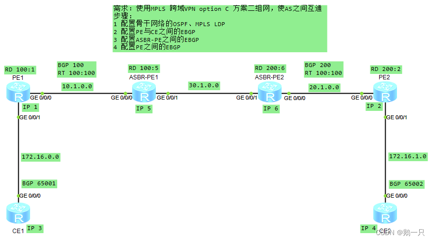
3 跨域VPN-OptionC(Inter-Provider Backbones Option C)方式:PE间通过Multi-hop MP-EBGP发布标签VPN-IPv4路由,也称为Multihop EBGP redistribution of labeled VPN-IPv4 routes。
配置举例:跨域VPN-OptionA
配置要点
1 ASBR-PE之间都认为对方是自己的CE。
2 同一AS内的ASBR-PE与PE的VPN实例的VPN-Target应能匹配,不同AS的PE的VPN实例的VPN-Target则不需要匹配。
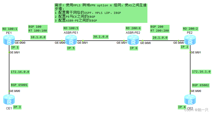
需求:使用MPLS 跨域VPN option A 组网,使AS之间互通
步骤:
1 配置骨干网络的OSPF、MPLS LDP、IBGP
2 配置PE与CE之间的EBGP
3 配置ASBR-PE之间的EBGP
PE1配置
#
 sysname PE1
#
router id 1.1.1.1
#
ip vpn-instance vpn1
 ipv4-family
  route-distinguisher 100:1
  vpn-target 100:100 export-extcommunity
  vpn-target 100:100 import-extcommunity
#
mpls lsr-id 1.1.1.1
mpls
#
mpls ldp
#
interface GigabitEthernet0/0/0
 ip address 10.1.0.1 255.255.255.0
 ospf enable 1 area 0.0.0.0
 mpls
 mpls ldp
#
interface GigabitEthernet0/0/1
 ip binding vpn-instance vpn1
 ip address 172.16.0.1 255.255.255.0
#
interface LoopBack0
 ip address 1.1.1.1 255.255.255.255
 ospf enable 1 area 0.0.0.0
#
bgp 100
 peer 5.5.5.5 as-number 100
 peer 5.5.5.5 connect-interface LoopBack0
 #
 ipv4-family unicast
  undo synchronization
  peer 5.5.5.5 enable
 #
 ipv4-family vpnv4
  policy vpn-target
  peer 5.5.5.5 enable
 #
 ipv4-family vpn-instance vpn1
  import-route direct
  peer 172.16.0.3 as-number 65001
#
ospf 1 router-id 1.1.1.1
 area 0.0.0.0
#
PE2配置
#
 sysname PE2
#
router id 2.2.2.2
#
ip vpn-instance vpn1
 ipv4-family
  route-distinguisher 200:2
  vpn-target 200:200 export-extcommunity
  vpn-target 200:200 import-extcommunity
#
mpls lsr-id 2.2.2.2
mpls
#
mpls ldp
#
interface GigabitEthernet0/0/0
 ip address 20.1.0.2 255.255.255.0
 ospf enable 1 area 0.0.0.0
 mpls
 mpls ldp
#
interface GigabitEthernet0/0/1
 ip binding vpn-instance vpn1
 ip address 172.16.1.2 255.255.255.0
#
interface LoopBack0
 ip address 2.2.2.2 255.255.255.255
 ospf enable 1 area 0.0.0.0
#
bgp 200
 peer 6.6.6.6 as-number 200
 peer 6.6.6.6 connect-interface LoopBack0
 #
 ipv4-family unicast
  undo synchronization
  peer 6.6.6.6 enable
 #
 ipv4-family vpnv4
  policy vpn-target
  peer 6.6.6.6 enable
 #
 ipv4-family vpn-instance vpn1
  import-route direct
  peer 172.16.1.4 as-number 65002
#
ospf 1 router-id 2.2.2.2
 area 0.0.0.0
#
CE1配置
#
 sysname CE1
#
router id 3.3.3.3
#
interface GigabitEthernet0/0/0
 ip address 172.16.0.3 255.255.255.0
#
interface LoopBack0
 ip address 3.3.3.3 255.255.255.255
#
bgp 65001
 peer 172.16.0.1 as-number 100
 #
 ipv4-family unicast
  undo synchronization
  import-route direct
  peer 172.16.0.1 enable
#
CE2配置
#
 sysname CE2
#
router id 4.4.4.4
#
interface GigabitEthernet0/0/0
 ip address 172.16.1.4 255.255.255.0
#
interface LoopBack0
 ip address 4.4.4.4 255.255.255.255
#
bgp 65002
 peer 172.16.1.2 as-number 200
 #
 ipv4-family unicast
  undo synchronization
  import-route direct
  peer 172.16.1.2 enable
#
ASBR-PE1配置
#
 sysname ASBR-PE1
#
router id 5.5.5.5
#
ip vpn-instance vpn1
 ipv4-family
  route-distinguisher 100:5
  vpn-target 100:100 export-extcommunity
  vpn-target 100:100 import-extcommunity
#
mpls lsr-id 5.5.5.5
mpls
#
mpls ldp
#
interface GigabitEthernet0/0/0
 ip address 10.1.0.5 255.255.255.0
 ospf enable 1 area 0.0.0.0
 mpls
 mpls ldp
#
interface GigabitEthernet0/0/1
 ip binding vpn-instance vpn1
 ip address 30.1.0.5 255.255.255.0
#
interface LoopBack0
 ip address 5.5.5.5 255.255.255.255
 ospf enable 1 area 0.0.0.0
#
bgp 100
 peer 1.1.1.1 as-number 100
 peer 1.1.1.1 connect-interface LoopBack0
 #
 ipv4-family unicast
  undo synchronization
  peer 1.1.1.1 enable
 #
 ipv4-family vpnv4
  policy vpn-target
  peer 1.1.1.1 enable
 #
 ipv4-family vpn-instance vpn1
  import-route direct
  peer 30.1.0.6 as-number 200       //与ASBR-PE2建立EBGP
#
ospf 1 router-id 5.5.5.5
 area 0.0.0.0
#
ASBR-PE2配置
#
 sysname ASBR-PE2
#
router id 6.6.6.6
#
ip vpn-instance vpn1
 ipv4-family
  route-distinguisher 200:6
  vpn-target 200:200 export-extcommunity
  vpn-target 200:200 import-extcommunity
#
mpls lsr-id 6.6.6.6
mpls
#
mpls ldp
#
interface GigabitEthernet0/0/0
 ip address 20.1.0.6 255.255.255.0
 ospf enable 1 area 0.0.0.0
 mpls
 mpls ldp
#
interface GigabitEthernet0/0/1
 ip binding vpn-instance vpn1
 ip address 30.1.0.6 255.255.255.0
#
interface LoopBack0
 ip address 6.6.6.6 255.255.255.255
 ospf enable 1 area 0.0.0.0
#
bgp 200
 peer 2.2.2.2 as-number 200
 peer 2.2.2.2 connect-interface LoopBack0
 #
 ipv4-family unicast
  undo synchronization
  peer 2.2.2.2 enable
 #
 ipv4-family vpnv4
  policy vpn-target
  peer 2.2.2.2 enable
 #
 ipv4-family vpn-instance vpn1
  import-route direct
  peer 30.1.0.5 as-number 100        //与ASBR-PE1建立EBGP
#
ospf 1 router-id 6.6.6.6
 area 0.0.0.0
#
测试结果
<CE1>ping 4.4.4.4
  PING 4.4.4.4: 56  data bytes, press CTRL_C to break
    Reply from 4.4.4.4: bytes=56 Sequence=1 ttl=251 time=50 ms
    Reply from 4.4.4.4: bytes=56 Sequence=2 ttl=251 time=30 ms
    Reply from 4.4.4.4: bytes=56 Sequence=3 ttl=251 time=40 ms
    Reply from 4.4.4.4: bytes=56 Sequence=4 ttl=251 time=40 ms
    Reply from 4.4.4.4: bytes=56 Sequence=5 ttl=251 time=60 ms

  --- 4.4.4.4 ping statistics ---
    5 packet(s) transmitted
    5 packet(s) received
    0.00% packet loss
    round-trip min/avg/max = 30/44/60 ms
配置成功
配置举例:跨域VPN-OptionB
配置思路
两个ASBR通过MP-EBGP交换它们从各自AS的PE设备接收的标签VPN-IPv4路由,再把VPN-IPv4路由发布出去。
相关命令
开启ASBR按下一跳为VPNv4路由分标签(为具有相同路由下一跳和出标签的路由分配一个标签,用来减少设备压力)
[ASBR-PE1-bgp-af-vpnv4]apply-label per-nexthop配置步骤
1 ASBR-PE不需要配置VPN实例。不同AS的PE的VPN实例RT需要相同。
2 ASBR-PE之间的接口开启mpls。
3 ASBR-PE之间建立EBGP关系。
4 在ASBR-PE的BGP视图中关闭VPNV4下的policy vpn-target,开启VPNV4下的按下一跳为VPNv4路由分标签。
以OptionA的图为例,需要修改ASBR-PE和PE2的配置
ASBR-PE1配置
#
 sysname ASBR-PE1
#
router id 5.5.5.5
#
mpls lsr-id 5.5.5.5
mpls
#
mpls ldp
#
interface GigabitEthernet0/0/0
 ip address 10.1.0.5 255.255.255.0
 ospf enable 1 area 0.0.0.0
 mpls
 mpls ldp
#
interface GigabitEthernet0/0/1
 ip address 30.1.0.5 255.255.255.0
 mpls                                     //与ASBR-PE2相连的接口开启MPLS
#
interface LoopBack0
 ip address 5.5.5.5 255.255.255.255
 ospf enable 1 area 0.0.0.0
#
bgp 100
 peer 1.1.1.1 as-number 100
 peer 1.1.1.1 connect-interface LoopBack0
 peer 30.1.0.6 as-number 200               //与ASBR-PE2建立BGP
 #
 ipv4-family unicast
  undo synchronization
  peer 1.1.1.1 enable
  peer 30.1.0.6 enable
 #
 ipv4-family vpnv4
  undo policy vpn-target                 //关闭VT策略
  apply-label per-nexthop                //开启vpnv4相同下一跳的分配相同标签的功能
  peer 1.1.1.1 enable
  peer 30.1.0.6 enable                   //开启ASBR-PE2的接口到vpnv4
#
ospf 1 router-id 5.5.5.5
 area 0.0.0.0
#
ASBR-PE2配置
#
 sysname ASBR-PE2
#
router id 6.6.6.6
#
mpls lsr-id 6.6.6.6
mpls
#
mpls ldp
#
interface GigabitEthernet0/0/0
 ip address 20.1.0.6 255.255.255.0
 ospf enable 1 area 0.0.0.0
 mpls
 mpls ldp
#
interface GigabitEthernet0/0/1
 ip address 30.1.0.6 255.255.255.0
 mpls
#
interface LoopBack0
 ip address 6.6.6.6 255.255.255.255
 ospf enable 1 area 0.0.0.0
#
bgp 200
 peer 2.2.2.2 as-number 200
 peer 2.2.2.2 connect-interface LoopBack0
 peer 30.1.0.5 as-number 100
 #
 ipv4-family unicast
  undo synchronization
  peer 2.2.2.2 enable
  peer 30.1.0.5 enable
 #
 ipv4-family vpnv4
  undo policy vpn-target
  apply-label per-nexthop
  peer 2.2.2.2 enable
  peer 30.1.0.5 enable
#
ospf 1 router-id 6.6.6.6
 area 0.0.0.0
#
PE2配置
#
 sysname PE2
#
router id 2.2.2.2
#
ip vpn-instance vpn1
 ipv4-family
  route-distinguisher 200:2
  vpn-target 100:100 export-extcommunity          //修改成和PE1一样的RT
  vpn-target 100:100 import-extcommunity
#
mpls lsr-id 2.2.2.2
mpls
#
mpls ldp
#
interface GigabitEthernet0/0/0
 ip address 20.1.0.2 255.255.255.0
 ospf enable 1 area 0.0.0.0
 mpls
 mpls ldp
#
interface GigabitEthernet0/0/1
 ip binding vpn-instance vpn1
 ip address 172.16.1.2 255.255.255.0
#
interface LoopBack0
 ip address 2.2.2.2 255.255.255.255
 ospf enable 1 area 0.0.0.0
#
bgp 200
 peer 6.6.6.6 as-number 200
 peer 6.6.6.6 connect-interface LoopBack0
 #
 ipv4-family unicast
  undo synchronization
  peer 6.6.6.6 enable
 #
 ipv4-family vpnv4
  policy vpn-target
  peer 6.6.6.6 enable
 #
 ipv4-family vpn-instance vpn1
  import-route direct
  peer 172.16.1.4 as-number 65002
#
ospf 1 router-id 2.2.2.2
 area 0.0.0.0
#
测试结果
<CE1>ping 4.4.4.4
  PING 4.4.4.4: 56  data bytes, press CTRL_C to break
    Reply from 4.4.4.4: bytes=56 Sequence=1 ttl=251 time=50 ms
    Reply from 4.4.4.4: bytes=56 Sequence=2 ttl=251 time=60 ms
    Reply from 4.4.4.4: bytes=56 Sequence=3 ttl=251 time=40 ms
    Reply from 4.4.4.4: bytes=56 Sequence=4 ttl=251 time=40 ms
    Reply from 4.4.4.4: bytes=56 Sequence=5 ttl=251 time=50 ms

  --- 4.4.4.4 ping statistics ---
    5 packet(s) transmitted
    5 packet(s) received
    0.00% packet loss
    round-trip min/avg/max = 40/48/60 ms
测试配置成功
配置举例:跨域VPN-OptionC
配置思路
ASBR不维护或发布VPN-IPv4路由,PE之间直接交换VPN-IPv4路由。
方案一
相关命令
开启发送标签的能力
[PE1-bgp-af-ipv4]peer 1.1.1.1 label-route-capability配置要点
1 ASBR-PE不需要配置VPN实例。不同AS的PE的VPN实例RT需要相同。
2 ASBR-PE之间的接口开启mpls。
3 ASBR-PE与PE之间IBGP开启发送标签的能力
4 ASBR-PE之间建立EBGP关系,开启发送标签的能力。
5 在ASBR-PE上配置路由策略:对于向对端ASBR-PE发布的路由,分配MPLS标签;对于向本AS的PE发布的路由,如果是带标签的IPv4路由,为其分配新的MPLS标签。
6 PE之间建立EBGP关系。

以OptionB的图为例,需要修改ASBR-PE和PE的配置
ASBR-PE1配置
#
 sysname ASBR-PE1
#
router id 5.5.5.5
#
mpls lsr-id 5.5.5.5
mpls
#
mpls ldp
#
interface GigabitEthernet0/0/0
 ip address 10.1.0.5 255.255.255.0
 ospf enable 1 area 0.0.0.0
 mpls
 mpls ldp
#
interface GigabitEthernet0/0/1
 ip address 30.1.0.5 255.255.255.0
 mpls                                        //朝向对端ASBR-PE的接口开启mpls
#
interface LoopBack0
 ip address 5.5.5.5 255.255.255.255
 ospf enable 1 area 0.0.0.0
#
bgp 100
 peer 1.1.1.1 as-number 100
 peer 1.1.1.1 connect-interface LoopBack0
 peer 30.1.0.6 as-number 200
 #
 ipv4-family unicast
  undo synchronization
  network 1.1.1.1 255.255.255.255           //将本端PE的路由发布给对端ASBR
  peer 1.1.1.1 enable
  peer 1.1.1.1 route-policy p2 export       //对本端PE应用策略P2
  peer 1.1.1.1 label-route-capability       //对本端PE开启打标签的能力
  peer 30.1.0.6 enable
  peer 30.1.0.6 route-policy p1 export      //对ASBR应用策略P1
  peer 30.1.0.6 label-route-capability      //对ASBR开启打标签的能力
 #
 ipv4-family vpnv4
  policy vpn-target
  peer 1.1.1.1 enable
#
ospf 1 router-id 5.5.5.5
 area 0.0.0.0
#
route-policy p1 permit node 1     //配置策略P1,分配标签
 apply mpls-label
#
route-policy p2 permit node 1     //配置策略P2,如果带标签,则分配新标签
 if-match mpls-label
 apply mpls-label
#
ASBR-PE2配置
#
 sysname ASBR-PE2
#
router id 6.6.6.6
#
mpls lsr-id 6.6.6.6
mpls
#
mpls ldp
#
interface GigabitEthernet0/0/0
 ip address 20.1.0.6 255.255.255.0
 ospf enable 1 area 0.0.0.0
 mpls
 mpls ldp
#
interface GigabitEthernet0/0/1
 ip address 30.1.0.6 255.255.255.0
 mpls
#
interface LoopBack0
 ip address 6.6.6.6 255.255.255.255
 ospf enable 1 area 0.0.0.0
#
bgp 200
 peer 2.2.2.2 as-number 200
 peer 2.2.2.2 connect-interface LoopBack0
 peer 30.1.0.5 as-number 100
 #
 ipv4-family unicast
  undo synchronization
  network 2.2.2.2 255.255.255.255
  peer 2.2.2.2 enable
  peer 2.2.2.2 route-policy p2 export
  peer 2.2.2.2 label-route-capability
  peer 30.1.0.5 enable
  peer 30.1.0.5 route-policy p1 export
  peer 30.1.0.5 label-route-capability
 #
 ipv4-family vpnv4
  policy vpn-target
  peer 2.2.2.2 enable
#
ospf 1 router-id 6.6.6.6
 area 0.0.0.0
#
route-policy p1 permit node 1
 apply mpls-label
#
route-policy p2 permit node 1
 if-match mpls-label
 apply mpls-label
#
PE1配置
#
 sysname PE1
#
router id 1.1.1.1
#
ip vpn-instance vpn1
 ipv4-family
  route-distinguisher 100:1
  vpn-target 100:100 export-extcommunity
  vpn-target 100:100 import-extcommunity
#
mpls lsr-id 1.1.1.1
mpls
#
mpls ldp
#
interface GigabitEthernet0/0/0
 ip address 10.1.0.1 255.255.255.0
 ospf enable 1 area 0.0.0.0
 mpls
 mpls ldp
#
interface GigabitEthernet0/0/1
 ip binding vpn-instance vpn1
 ip address 172.16.0.1 255.255.255.0
#
interface LoopBack0
 ip address 1.1.1.1 255.255.255.255
 ospf enable 1 area 0.0.0.0
#
bgp 100
 peer 2.2.2.2 as-number 200                    //与对端PE建立EBGP,配置最大跳数等
 peer 2.2.2.2 ebgp-max-hop 10
 peer 2.2.2.2 connect-interface LoopBack0
 peer 5.5.5.5 as-number 100
 peer 5.5.5.5 connect-interface LoopBack0
 #
 ipv4-family unicast
  undo synchronization
  peer 2.2.2.2 enable
  peer 5.5.5.5 enable
  peer 5.5.5.5 label-route-capability       //开启对本端ASBR-PE分配标签的能力
 #
 ipv4-family vpnv4
  policy vpn-target
  peer 2.2.2.2 enable                       //开启对端PE的vpnv4
  peer 5.5.5.5 enable
 #
 ipv4-family vpn-instance vpn1
  import-route direct
  peer 172.16.0.3 as-number 65001
#
ospf 1 router-id 1.1.1.1
 area 0.0.0.0
#
PE2配置
#
 sysname PE2
#
router id 2.2.2.2
#
ip vpn-instance vpn1
 ipv4-family
  route-distinguisher 200:2
  vpn-target 100:100 export-extcommunity
  vpn-target 100:100 import-extcommunity
#
mpls lsr-id 2.2.2.2
mpls
#
mpls ldp
#
interface GigabitEthernet0/0/0
 ip address 20.1.0.2 255.255.255.0
 ospf enable 1 area 0.0.0.0
 mpls
 mpls ldp
#
interface GigabitEthernet0/0/1
 ip binding vpn-instance vpn1
 ip address 172.16.1.2 255.255.255.0
#
interface LoopBack0
 ip address 2.2.2.2 255.255.255.255
 ospf enable 1 area 0.0.0.0
#
bgp 200
 peer 1.1.1.1 as-number 100
 peer 1.1.1.1 ebgp-max-hop 10
 peer 1.1.1.1 connect-interface LoopBack0
 peer 6.6.6.6 as-number 200
 peer 6.6.6.6 connect-interface LoopBack0
 #
 ipv4-family unicast
  undo synchronization
  peer 1.1.1.1 enable
  peer 6.6.6.6 enable
  peer 6.6.6.6 label-route-capability
 #
 ipv4-family vpnv4
  policy vpn-target
  peer 1.1.1.1 enable
  peer 6.6.6.6 enable
 #
 ipv4-family vpn-instance vpn1
  import-route direct
  peer 172.16.1.4 as-number 65002
#
ospf 1 router-id 2.2.2.2
 area 0.0.0.0
#
测试结果
<CE1>ping 4.4.4.4
  PING 4.4.4.4: 56  data bytes, press CTRL_C to break
    Reply from 4.4.4.4: bytes=56 Sequence=1 ttl=251 time=60 ms
    Reply from 4.4.4.4: bytes=56 Sequence=2 ttl=251 time=50 ms
    Reply from 4.4.4.4: bytes=56 Sequence=3 ttl=251 time=50 ms
    Reply from 4.4.4.4: bytes=56 Sequence=4 ttl=251 time=40 ms
    Reply from 4.4.4.4: bytes=56 Sequence=5 ttl=251 time=40 ms

  --- 4.4.4.4 ping statistics ---
    5 packet(s) transmitted
    5 packet(s) received
    0.00% packet loss
    round-trip min/avg/max = 40/48/60 ms
测试成功
方案二
相关命令
配置LDP为带标签的公网BGP路由分标签的能力
[ASBR-PE1-mpls]lsp-trigger bgp-label-route配置要点(在方案一的基础上)
1 ASBR-PE与PE之间不建立IBGP关系。
2 ASBR-PE上的BGP路由引入OSPF进程。
以OptionC 方案一 的图为例,需要修改ASBR-PE和PE的配置
ASBR-PE1配置
#
 sysname ASBR-PE1
#
router id 5.5.5.5
#
mpls lsr-id 5.5.5.5
mpls
 lsp-trigger bgp-label-route         //配置LDP为带标签的公网BGP路由分标签的能力
#
mpls ldp
#
interface GigabitEthernet0/0/0
 ip address 10.1.0.5 255.255.255.0
 ospf enable 1 area 0.0.0.0
 mpls
 mpls ldp
#
interface GigabitEthernet0/0/1
 ip address 30.1.0.5 255.255.255.0
 mpls
#
interface LoopBack0
 ip address 5.5.5.5 255.255.255.255
 ospf enable 1 area 0.0.0.0
#
bgp 100                                //不与PE1建立IBGP
 peer 30.1.0.6 as-number 200
 #
 ipv4-family unicast
  undo synchronization
  network 1.1.1.1 255.255.255.255
  peer 30.1.0.6 enable
  peer 30.1.0.6 route-policy p1 export
  peer 30.1.0.6 label-route-capability
#
ospf 1 router-id 5.5.5.5
 import-route bgp                      //在OSPF中引入BGP路由
 area 0.0.0.0
#
route-policy p1 permit node 1
 apply mpls-label
#
ASBR-PE2配置
#
 sysname ASBR-PE2
#
router id 6.6.6.6
#
mpls lsr-id 6.6.6.6
mpls
 lsp-trigger bgp-label-route
#
mpls ldp
#
interface GigabitEthernet0/0/0
 ip address 20.1.0.6 255.255.255.0
 ospf enable 1 area 0.0.0.0
 mpls
 mpls ldp
#
interface GigabitEthernet0/0/1
 ip address 30.1.0.6 255.255.255.0
 mpls
#
interface LoopBack0
 ip address 6.6.6.6 255.255.255.255
 ospf enable 1 area 0.0.0.0
#
bgp 200
 peer 30.1.0.5 as-number 100
 #
 ipv4-family unicast
  undo synchronization
  network 2.2.2.2 255.255.255.255
  peer 30.1.0.5 enable
  peer 30.1.0.5 route-policy p1 export
  peer 30.1.0.5 label-route-capability
#
ospf 1 router-id 6.6.6.6
 import-route bgp
 area 0.0.0.0
#
route-policy p1 permit node 1
 apply mpls-label
#
PE1配置
#
 sysname PE1
#
router id 1.1.1.1
#
ip vpn-instance vpn1
 ipv4-family
  route-distinguisher 100:1
  vpn-target 100:100 export-extcommunity
  vpn-target 100:100 import-extcommunity
#
mpls lsr-id 1.1.1.1
mpls
#
mpls ldp
#
interface GigabitEthernet0/0/0
 ip address 10.1.0.1 255.255.255.0
 ospf enable 1 area 0.0.0.0
 mpls
 mpls ldp
#
interface GigabitEthernet0/0/1
 ip binding vpn-instance vpn1
 ip address 172.16.0.1 255.255.255.0
#
interface LoopBack0
 ip address 1.1.1.1 255.255.255.255
 ospf enable 1 area 0.0.0.0
#
bgp 100                                      //不与ASBR-PE1建立BGP
 peer 2.2.2.2 as-number 200
 peer 2.2.2.2 ebgp-max-hop 10
 peer 2.2.2.2 connect-interface LoopBack0
 #
 ipv4-family unicast
  undo synchronization
  peer 2.2.2.2 enable
 #
 ipv4-family vpnv4
  policy vpn-target
  peer 2.2.2.2 enable
 #
 ipv4-family vpn-instance vpn1
  import-route direct
  peer 172.16.0.3 as-number 65001
#
ospf 1 router-id 1.1.1.1
 area 0.0.0.0
#
PE2配置
#
 sysname PE2
#
router id 2.2.2.2
#
ip vpn-instance vpn1
 ipv4-family
  route-distinguisher 200:2
  vpn-target 100:100 export-extcommunity
  vpn-target 100:100 import-extcommunity
#
mpls lsr-id 2.2.2.2
mpls
#
mpls ldp
#
interface GigabitEthernet0/0/0
 ip address 20.1.0.2 255.255.255.0
 ospf enable 1 area 0.0.0.0
 mpls
 mpls ldp
#
interface GigabitEthernet0/0/1
 ip binding vpn-instance vpn1
 ip address 172.16.1.2 255.255.255.0
#
interface LoopBack0
 ip address 2.2.2.2 255.255.255.255
 ospf enable 1 area 0.0.0.0
#
bgp 200
 peer 1.1.1.1 as-number 100
 peer 1.1.1.1 ebgp-max-hop 10
 peer 1.1.1.1 connect-interface LoopBack0
 #
 ipv4-family unicast
  undo synchronization
  peer 1.1.1.1 enable
 #
 ipv4-family vpnv4
  policy vpn-target
  peer 1.1.1.1 enable
 #
 ipv4-family vpn-instance vpn1
  import-route direct
  peer 172.16.1.4 as-number 65002
#
ospf 1 router-id 2.2.2.2
 area 0.0.0.0
#
测试结果
<CE1>ping 4.4.4.4
  PING 4.4.4.4: 56  data bytes, press CTRL_C to break
    Reply from 4.4.4.4: bytes=56 Sequence=1 ttl=251 time=70 ms
    Reply from 4.4.4.4: bytes=56 Sequence=2 ttl=251 time=40 ms
    Reply from 4.4.4.4: bytes=56 Sequence=3 ttl=251 time=30 ms
    Reply from 4.4.4.4: bytes=56 Sequence=4 ttl=251 time=50 ms
    Reply from 4.4.4.4: bytes=56 Sequence=5 ttl=251 time=50 ms

  --- 4.4.4.4 ping statistics ---
    5 packet(s) transmitted
    5 packet(s) received
    0.00% packet loss
    round-trip min/avg/max = 30/48/70 ms
测试成功
方案二(带RR场景) 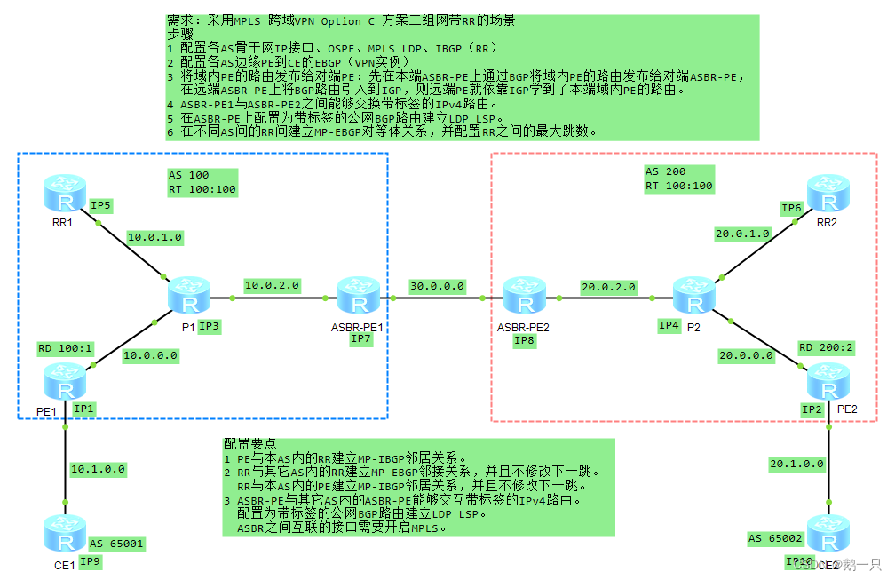
需求:采用MPLS 跨域VPN Option C 方案二组网带RR的场景
配置步骤
1 配置各AS骨干网IP接口、OSPF、MPLS LDP、IBGP(RR)
2 配置各AS边缘PE到CE的EBGP(VPN实例)
3 将域内PE的路由发布给对端PE:先在本端ASBR-PE上通过BGP将域内PE的路由发布给对端ASBR-PE,在远端ASBR-PE上将BGP路由引入到IGP,则远端PE就依靠IGP学到了本端域内PE的路由。
4 ASBR-PE1与ASBR-PE2之间能够交换带标签的IPv4路由。
5 在ASBR-PE上配置为带标签的公网BGP路由建立LDP LSP。
6 在不同AS间的RR间建立MP-EBGP对等体关系,并配置RR之间的最大跳数。
配置要点
1 PE与本AS内的RR建立MP-IBGP邻居关系。
2 RR与其它AS内的RR建立MP-EBGP邻接关系,并且不修改下一跳。
RR与本AS内的PE建立MP-IBGP邻居关系,并且不修改下一跳。
3 ASBR-PE与其它AS内的ASBR-PE能够交互带标签的IPv4路由。
配置为带标签的公网BGP路由建立LDP LSP。
ASBR之间互联的接口需要开启MPLS。
ASBR-PE1配置
#
 sysname ASBR-PE1
#
mpls lsr-id 7.7.7.7
mpls
 lsp-trigger bgp-label-route     //配置为带标签的公网BGP路由建立LDP LSP
#
mpls ldp
#
interface GigabitEthernet0/0/0
 ip address 10.0.2.7 255.255.255.0
 ospf enable 1 area 0.0.0.0
 mpls
 mpls ldp
#
interface GigabitEthernet0/0/1
 ip address 30.0.0.7 255.255.255.0
 mpls                                 //与ASBR-PE2的直连接口开启MPLS
#
interface LoopBack0
 ip address 7.7.7.7 255.255.255.255
 ospf enable 1 area 0.0.0.0
#
bgp 100
 peer 30.0.0.8 as-number 200
 #
 ipv4-family unicast
  undo synchronization
  network 5.5.5.5 255.255.255.255
  peer 30.0.0.8 enable
  peer 30.0.0.8 route-policy p1 export    //对向ASBR-PE2发布的路由应用路由策略
  peer 30.0.0.8 label-route-capability    //开启与ASBR-PE2交换标签IPv4路由的能力
#
ospf 1 router-id 7.7.7.7
 import-route bgp                       //将BGP路由引入到IGP
 area 0.0.0.0
#
route-policy p1 permit node 1           //创建路由策略
 apply mpls-label
#
ASBR-PE2配置
#
 sysname ASBR-PE2
#
mpls lsr-id 8.8.8.8
mpls
 lsp-trigger bgp-label-route
#
mpls ldp
#
interface GigabitEthernet0/0/0
 ip address 20.0.2.8 255.255.255.0
 ospf enable 1 area 0.0.0.0
 mpls
 mpls ldp
#
interface GigabitEthernet0/0/1
 ip address 30.0.0.8 255.255.255.0
 mpls
#
interface LoopBack0
 ip address 8.8.8.8 255.255.255.255
 ospf enable 1 area 0.0.0.0
#
bgp 200
 peer 30.0.0.7 as-number 100
 #
 ipv4-family unicast
  undo synchronization
  network 6.6.6.6 255.255.255.255
  peer 30.0.0.7 enable
  peer 30.0.0.7 route-policy p1 export
  peer 30.0.0.7 label-route-capability
#
ospf 1 router-id 8.8.8.8
 import-route bgp
 area 0.0.0.0
#
route-policy p1 permit node 1
 apply mpls-label
#
RR1配置
#
 sysname RR1
#
mpls lsr-id 5.5.5.5
mpls
#
mpls ldp
#
interface GigabitEthernet0/0/0
 ip address 10.0.1.5 255.255.255.0
 mpls
 mpls ldp
#
interface LoopBack0
 ip address 5.5.5.5 255.255.255.255
#
bgp 100
 peer 1.1.1.1 as-number 100
 peer 1.1.1.1 connect-interface LoopBack0
 peer 6.6.6.6 as-number 200
 peer 6.6.6.6 ebgp-max-hop 10
 peer 6.6.6.6 connect-interface LoopBack0
 #
 ipv4-family unicast
  undo synchronization
  peer 1.1.1.1 enable
  peer 1.1.1.1 reflect-client            //与PE1建立反射
  peer 1.1.1.1 next-hop-invariable       //配置下一跳不变,使流量不经过RR1,只提供路由反射。
  peer 6.6.6.6 enable
  peer 6.6.6.6 next-hop-invariable       //配置下一跳不变,使流量不经过RR1,只提供路由反射。
 #
 ipv4-family vpnv4
  undo policy vpn-target               //关闭VT策略
  peer 1.1.1.1 enable
  peer 6.6.6.6 enable
#
ospf 1 router-id 5.5.5.5
 area 0.0.0.0
  network 0.0.0.0 255.255.255.255
#
RR2配置
#
 sysname RR2
#
mpls lsr-id 6.6.6.6
mpls
#
mpls ldp
#
interface GigabitEthernet0/0/0
 ip address 20.0.1.6 255.255.255.0
 mpls
 mpls ldp
#
interface LoopBack0
 ip address 6.6.6.6 255.255.255.255
#
bgp 200
 peer 2.2.2.2 as-number 200
 peer 2.2.2.2 connect-interface LoopBack0
 peer 5.5.5.5 as-number 100
 peer 5.5.5.5 ebgp-max-hop 10
 peer 5.5.5.5 connect-interface LoopBack0
 #
 ipv4-family unicast
  undo synchronization
  peer 2.2.2.2 enable
  peer 2.2.2.2 reflect-client
  peer 2.2.2.2 next-hop-invariable
  peer 5.5.5.5 enable
  peer 5.5.5.5 next-hop-invariable
 #
 ipv4-family vpnv4
  undo policy vpn-target
  peer 2.2.2.2 enable
  peer 5.5.5.5 enable
#
ospf 1 router-id 6.6.6.6
 area 0.0.0.0
  network 0.0.0.0 255.255.255.255
#
PE1配置
#
 sysname PE1
#
ip vpn-instance vpn1
 ipv4-family
  route-distinguisher 100:1
  vpn-target 100:100 export-extcommunity
  vpn-target 100:100 import-extcommunity
#
mpls lsr-id 1.1.1.1
mpls
#
mpls ldp
#
interface GigabitEthernet0/0/0
 ip address 10.0.0.1 255.255.255.0
 ospf enable 1 area 0.0.0.0
 mpls
 mpls ldp
#
interface GigabitEthernet0/0/1
 ip binding vpn-instance vpn1
 ip address 10.1.0.1 255.255.255.0
#
interface LoopBack0
 ip address 1.1.1.1 255.255.255.255
 ospf enable 1 area 0.0.0.0
#
bgp 100
 peer 5.5.5.5 as-number 100
 peer 5.5.5.5 connect-interface LoopBack0
 #
 ipv4-family unicast
  undo synchronization
  peer 5.5.5.5 enable
 #
 ipv4-family vpnv4
  policy vpn-target
  peer 5.5.5.5 enable
 #
 ipv4-family vpn-instance vpn1
  import-route direct
  peer 10.1.0.9 as-number 65001
#
ospf 1 router-id 1.1.1.1
 area 0.0.0.0
#
PE2配置
#
 sysname PE2
#
ip vpn-instance vpn1
 ipv4-family
  route-distinguisher 200:2
  vpn-target 100:100 export-extcommunity
  vpn-target 100:100 import-extcommunity
#
mpls lsr-id 2.2.2.2
mpls
#
mpls ldp
#
interface GigabitEthernet0/0/0
 ip address 20.0.0.2 255.255.255.0
 ospf enable 1 area 0.0.0.0
 mpls
 mpls ldp
#
interface GigabitEthernet0/0/1
 ip binding vpn-instance vpn1
 ip address 20.1.0.2 255.255.255.0
#
interface LoopBack0
 ip address 2.2.2.2 255.255.255.255
 ospf enable 1 area 0.0.0.0
#
bgp 200
 peer 6.6.6.6 as-number 200
 peer 6.6.6.6 connect-interface LoopBack0
 #
 ipv4-family unicast
  undo synchronization
  peer 6.6.6.6 enable
 #
 ipv4-family vpnv4
  policy vpn-target
  peer 6.6.6.6 enable
 #
 ipv4-family vpn-instance vpn1
  import-route direct
  peer 20.1.0.10 as-number 65002
#
ospf 1 router-id 2.2.2.2
 area 0.0.0.0
#
P1配置
#
 sysname P1
#
mpls lsr-id 3.3.3.3
mpls
#
mpls ldp
#
interface GigabitEthernet0/0/0
 ip address 10.0.0.3 255.255.255.0
 mpls
 mpls ldp
#
interface GigabitEthernet0/0/1
 ip address 10.0.1.3 255.255.255.0
 mpls
 mpls ldp
#
interface GigabitEthernet0/0/2
 ip address 10.0.2.3 255.255.255.0
 mpls
 mpls ldp
#
interface NULL0
#
interface LoopBack0
 ip address 3.3.3.3 255.255.255.255
#
ospf 1 router-id 3.3.3.3
 area 0.0.0.0
  network 0.0.0.0 255.255.255.255
#
P2配置
#
 sysname P2
#
mpls lsr-id 4.4.4.4
mpls
#
mpls ldp
#
interface GigabitEthernet0/0/0
 ip address 20.0.0.4 255.255.255.0
 mpls
 mpls ldp
#
interface GigabitEthernet0/0/1
 ip address 20.0.1.4 255.255.255.0
 mpls
 mpls ldp
#
interface GigabitEthernet0/0/2
 ip address 20.0.2.4 255.255.255.0
 mpls
 mpls ldp
#
interface NULL0
#
interface LoopBack0
 ip address 4.4.4.4 255.255.255.255
#
ospf 1 router-id 4.4.4.4
 area 0.0.0.0
  network 0.0.0.0 255.255.255.255
#
CE1配置
#
 sysname CE1
#
interface GigabitEthernet0/0/0
 ip address 10.1.0.9 255.255.255.0
#
interface LoopBack0
 ip address 9.9.9.9 255.255.255.255
#
bgp 65001
 peer 10.1.0.1 as-number 100
 #
 ipv4-family unicast
  undo synchronization
  import-route direct
  peer 10.1.0.1 enable
#
CE2配置
#
 sysname CE2
#
interface GigabitEthernet0/0/0
 ip address 20.1.0.10 255.255.255.0
#
interface LoopBack0
 ip address 10.10.10.10 255.255.255.255
#
bgp 65002
 peer 20.1.0.2 as-number 200
 #
 ipv4-family unicast
  undo synchronization
  import-route direct
  peer 20.1.0.2 enable
#
测试结果
<CE1>ping 10.10.10.10
  PING 10.10.10.10: 56  data bytes, press CTRL_C to break
    Reply from 10.10.10.10: bytes=56 Sequence=1 ttl=245 time=80 ms
    Reply from 10.10.10.10: bytes=56 Sequence=2 ttl=245 time=80 ms
    Reply from 10.10.10.10: bytes=56 Sequence=3 ttl=245 time=100 ms
    Reply from 10.10.10.10: bytes=56 Sequence=4 ttl=245 time=100 ms
    Reply from 10.10.10.10: bytes=56 Sequence=5 ttl=245 time=90 ms

  --- 10.10.10.10 ping statistics ---
    5 packet(s) transmitted
    5 packet(s) received
    0.00% packet loss
    round-trip min/avg/max = 80/90/100 ms
测试成功
三种跨域方式的对比
| 跨域方式 | 特点 |
| OptionA | 优点是配置简单:ASBR之间不需要运行MPLS,也不需要为跨域进行特殊配置。 缺点是可扩展性差:ASBR需要管理所有VPN路由,为每个VPN创建VPN实例,这将导致ASBR上的VPNv4路由数量过大。并且,由于ASBR间是普通的IP转发,要求为每个跨域的VPN使用不同的接口(可以是子接口、物理接口、捆绑的逻辑接口),从而提高了对ASBR设备的要求。如果跨越多个自治域,中间域必须支持VPN业务,不仅配置量大,而且对中间域影响大。在需要跨域的VPN数量比较少的情况,可以优先考虑使用。 |
| OptionB | 不同于OptionA,OptionB方案不受ASBR之间互连链路数目的限制。 局限性:VPN的路由信息是通过AS之间的ASBR路由器来保存和扩散的,当VPN路由较多时,ASBR负担重,容易成为瓶颈点。因此在MP-EBGP方案中,需要维护VPN路由信息的ASBR一般不再负责公网IP转发。 |
| OptionC | VPN路由在入口PE和出口PE之间直接交换,不需要中间设备的保存和转发。 VPN的路由信息只出现在PE设备上,而P和ASBR路由器只负责报文的转发,使得中间域的设备可以不支持MPLS VPN业务,只需支持MPLS转发,ASBR设备不再成为性能瓶颈。因此跨域VPN-OptionC更适合在跨越多个AS时使用。 更适合支持MPLS VPN的负载分担。 缺点是维护一条端到端的BGP LSP连接,管理代价较大。 |


 229
229


 被折叠的 条评论
为什么被折叠?
被折叠的 条评论
为什么被折叠?
 到【灌水乐园】发言


