


按照要求搭建拓扑图:

在连线时候注意area0区域内的路由器连线的时候用的是串口,需要先在路由器添加接口,然后再用Serial线连接。

按照要求划分网段:
实际工作中划分考虑:
1.先按照网路中具体几种协议。
2.考虑具体由几个区域。
此处因为RIP所需要的网段较少,就按照一个OSPF区域划分。
172.16.0.0/16
	172.16.0.0/19    --- A0
		172.16.0.0/24 --- p2p骨干(一般24位,可用的主机位8位,可以容纳254台主机)
			172.16.0.0/30 (骨干一般只需要两个网段,所以给两位)
			172.16.0.4/30
			172.16.0.8/30
			172.16.0.12/30
			. . . .
		172.16.1.0/24 --- MA骨干
			172.16.1.0/29
			172.16.1.8/29
			172.16.1.16/29
			172.16.1.24/29
			. . . .
		172.16.2.0/24
		172.16.3.0/24
		. . .
	172.16.32.0/19   --- A1
	172.16.64.0/19   --- A2
	172.16.96.0/19   --- A3
	172.16.128.0/19  --- A4
	172.16.160.0/19  --- rip
		172.16.160.0/20
		172.16.176.0/20

	172.16.192.0/19 --- 保留(扩展的时候使用)
	172.16.224.0/19 --- 保留
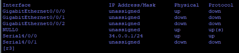
R3:

R4:


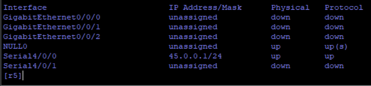
R5:

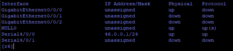
R6:

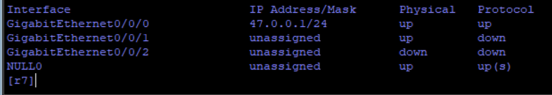
R7:

搭建MGRE环境
R3:
[r3]int t 0/0/0
[r3-Tunnel0/0/0]ip add 172.16.1.1 29
[r3-Tunnel0/0/0]tunnel-protocol gre p2mp
[r3-Tunnel0/0/0]source 34.0.0.1
Oct  7 2021 19:31:57-08:00 r3 %%01IFNET/4/LINK_STATE(l)[0]:The line protocol IP
on the interface Tunnel0/0/0 has entered the UP state.
[r3-Tunnel0/0/0]nhrp network-id 100
[r3-Tunnel0/0/0]nhrp entry multicast dynamic
R5:
[r5]int t 0/0/0
[r5-Tunnel0/0/0]ip add 172.16.1.2 29
[r5-Tunnel0/0/0]tunnel-protocol gre p2mp
[r5-Tunnel0/0/0]source Serial 4/0/0
Oct  7 2021 19:35:50-08:00 r5 %%01IFNET/4/LINK_STATE(l)[0]:The line protocol IP
on the interface Tunnel0/0/0 has entered the UP state.
[r5-Tunnel0/0/0]nhrp network-id 100
[r5-Tunnel0/0/0]nhrp entry 172.16.1.1 34.0.0.1 register
R6:
[r6]int t 0/0/0
[r6-Tunnel0/0/0]ip add 172.16.1.3 29
[r6-Tunnel0/0/0]tunnel-protocol gre p2mp
[r6-Tunnel0/0/0]source Serial 4/0/0
Oct  7 2021 19:39:01-08:00 r6 %%01IFNET/4/LINK_STATE(l)[0]:The line protocol IP
on the interface Tunnel0/0/0 has entered the UP state.
[r6-Tunnel0/0/0]nhrp network-id 100
[r6-Tunnel0/0/0]nhrp entry 172.16.1.1 34.0.0.1 register
R7:
[r7]int t 0/0/0
[r7-Tunnel0/0/0]ip add 172.16.1.4 29
[r7-Tunnel0/0/0]tunnel-protocol gre p2mp
[r7-Tunnel0/0/0]source GigabitEthernet 0/0/0
Oct  7 2021 19:41:44-08:00 r7 %%01IFNET/4/LINK_STATE(l)[0]:The line protocol IP
on the interface Tunnel0/0/0 has entered the UP state.
[r7-Tunnel0/0/0]nhrp network-id 100
[r7-Tunnel0/0/0]nhrp entry 172.16.1.1 34.0.0.1 register
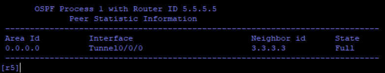
查看注册信息:

检验效果:

area0环回:
[r5]int l 0
[r5-LoopBack0]ip add 172.16.2.1 24
[r6]int l 0
[r6-LoopBack0]ip add 172.16.3.1 24
[r7-Tunnel0/0/0]int l 0
[r7-LoopBack0]ip add 172.16.4.1 24
区域一: AR1:
[Huawei]sys r1
[r1]int g 0/0/0
[r1-GigabitEthernet0/0/0]ip add 172.16.33.1 29
Oct  7 2021 19:52:20-08:00 r1 %%01IFNET/4/LINK_STATE(l)[0]:The line protocol IP
on the interface GigabitEthernet0/0/0 has entered the UP state.
[r1-GigabitEthernet0/0/0]int l0
[r1-LoopBack0]ip add 172.16.34.1 24
AR2:
[Huawei]sys r2
[r2]int g 0/0/0
[r2-GigabitEthernet0/0/0]ip add 172.16.33.2 29
Oct  7 2021 19:54:57-08:00 r2 %%01IFNET/4/LINK_STATE(l)[0]:The line protocol IP
on the interface GigabitEthernet0/0/0 has entered the UP state.
[r2-GigabitEthernet0/0/0]int l0
[r2-LoopBack0]ip add 172.16.35.1 24
AR3:
[r3]int g 0/0/0
[r3-GigabitEthernet0/0/0]ip add 172.16.33.3 29
Oct  7 2021 19:56:02-08:00 r3 %%01IFNET/4/LINK_STATE(l)[0]:The line protocol IP
on the interface GigabitEthernet0/0/0 has entered the UP state.
[r3-GigabitEthernet0/0/0]int l0
[r3-LoopBack0]ip add 172.16.36.1 24
[r3-LoopBack0]
区域二:
AR6:
[r6]int G 0/0/0
[r6-GigabitEthernet0/0/0]ip add 172.16.65.1 29
[r6-GigabitEthernet0/0/0]
Oct  7 2021 19:58:05-08:00 r6 %%01IFNET/4/LINK_STATE(l)[0]:The line protocol IP
on the interface GigabitEthernet0/0/0 has entered the UP state.
AR11:
[r11]int g 0/0/0
[r11-GigabitEthernet0/0/0]ip add 172.16.65.2 29
Oct  7 2021 19:59:09-08:00 r11 %%01IFNET/4/LINK_STATE(l)[0]:The line protocol IP
 on the interface GigabitEthernet0/0/0 has entered the UP state.
[r11-GigabitEthernet0/0/0]int g 0/0/1
[r11-GigabitEthernet0/0/1]ip add 172.16.65.9 29
Oct  7 2021 19:59:35-08:00 r11 %%01IFNET/4/LINK_STATE(l)[1]:The line protocol IP
 on the interface GigabitEthernet0/0/1 has entered the UP state.
[r11-GigabitEthernet0/0/1]int l0
[r11-LoopBack0]ip add 172.16.66.1 24
AR12:
[r12]int g 0/0/0
[r12-GigabitEthernet0/0/0]ip add 172.16.65.10 29
Oct  7 2021 20:01:02-08:00 r12 %%01IFNET/4/LINK_STATE(l)[0]:The line protocol IP
 on the interface GigabitEthernet0/0/0 has entered the UP state.
区域三:
AR7:
[r7]int g 0/0/1
[r7-GigabitEthernet0/0/1]ip add 172.16.97.1 29
[r7-GigabitEthernet0/0/1]
Oct  7 2021 20:02:27-08:00 r7 %%01IFNET/4/LINK_STATE(l)[0]:The line protocol IP
on the interface GigabitEthernet0/0/1 has entered the UP state.
AR8:
[Huawei]int g 0/0/0
[Huawei-GigabitEthernet0/0/0]q
[Huawei]sys r8
[r8]int g0/0/0
[r8-GigabitEthernet0/0/0]ip add 172.16.97.2 29
Oct  7 2021 20:03:41-08:00 r8 %%01IFNET/4/LINK_STATE(l)[0]:The line protocol IP
on the interface GigabitEthernet0/0/0 has entered the UP state.
[r8-GigabitEthernet0/0/0]int g 0/0/1
[r8-GigabitEthernet0/0/1]ip add 172.16.97.9 29
Oct  7 2021 20:03:56-08:00 r8 %%01IFNET/4/LINK_STATE(l)[1]:The line protocol IP
on the interface GigabitEthernet0/0/1 has entered the UP state.
[r8-GigabitEthernet0/0/1]int l0
[r8-LoopBack0]ip add 172.16.98.1 24
AR9:
[Huawei]sys r9
[r9]int g 0/0/0
[r9-GigabitEthernet0/0/0]ip add 172.16.97.10 29
Oct  7 2021 20:04:57-08:00 r9 %%01IFNET/4/LINK_STATE(l)[0]:The line protocol IP
on the interface GigabitEthernet0/0/0 has entered the UP state.
[r9-GigabitEthernet0/0/0]int g0/0/1
[r9-GigabitEthernet0/0/1]ip add 172.16.129.1 24
Oct  7 2021 20:05:51-08:00 r9 %%01IFNET/4/LINK_STATE(l)[1]:The line protocol IP
on the interface GigabitEthernet0/0/1 has entered the UP state.
[r9-GigabitEthernet0/0/1]int l0
[r9-LoopBack0]ip add 172.16.130.1 24
区域四:
AR10:
[Huawei]sys r10
[r10]int g0/0/0
[r10-GigabitEthernet0/0/0]ip add 172.16.129.2 29
Oct  7 2021 20:07:21-08:00 r10 %%01IFNET/4/LINK_STATE(l)[0]:The line protocol IP
 on the interface GigabitEthernet0/0/0 has entered the UP state.
[r10-GigabitEthernet0/0/0]int l0
[r10-LoopBack0]ip add 172.16.131.1 24
RIP:
AR12:
[r12]int l0
[r12-LoopBack0]ip add 172.16.160.1 20
[r12-LoopBack0]int l1
[r12-LoopBack1]ip add 172.16.176.1 20
激活OSPF: AR1:
[r1]ospf 1 router-id 1.1.1.1
[r1-ospf-1]a 1
[r1-ospf-1-area-0.0.0.1]network 172.16.0.0 0.0.255.255
AR2:
[r2]ospf 1 router-id 2.2.2.2
[r2-ospf-1]a 1
[r2-ospf-1-area-0.0.0.1]network 172.16.0.0 0.0.255.255
AR3:
[r3]ospf 1 router-id 3.3.3.3
[r3-ospf-1]a 1
[r3-ospf-1-area-0.0.0.1]network 172.16.32.0 0.0.7.255
[r3-ospf-1-area-0.0.0.1]a 0
[r3-ospf-1-area-0.0.0.0]network 172.16.1.1 0.0.0.0
AR5:
[r5]ospf 1 router-id 5.5.5.5
[r5-ospf-1]a 0
[r5-ospf-1-area-0.0.0.0]network 172.16.0.0 0.0.255.255
AR6:
[r6]ospf 1 router-id 6.6.6.6
[r6-ospf-1]a 0
[r6-ospf-1-area-0.0.0.0]network 172.16.0.0 0.0.3.255
[r6-ospf-1-area-0.0.0.0]q
[r6-ospf-1]a 2
[r6-ospf-1-area-0.0.0.2]network 172.16.65.1 0.0.0.0
AR7:
[r7]ospf 1 router-id 7.7.7.7
[r7-ospf-1]a 0
[r7-ospf-1-area-0.0.0.0]network 172.16.0.0 0.0.7.255
[r7-ospf-1-area-0.0.0.0]q
[r7-ospf-1]a 3
[r7-ospf-1-area-0.0.0.3]network 172.16.97.1 0.0.0.0
AR8:
[r8]ospf 1 router-id 8.8.8.8
[r8-ospf-1]a 3
[r8-ospf-1-area-0.0.0.3]network 172.16.0.0 0.0.255.255
AR9:
[r9]ospf 1 router-id 9.9.9.9
[r9-ospf-1]a 3
[r9-ospf-1-area-0.0.0.3]network 172.16.97.10 0.0.0.0
[r9-ospf-1-area-0.0.0.3]q
[r9-ospf-1]a 4
[r9-ospf-1-area-0.0.0.4]netw
[r9-ospf-1-area-0.0.0.4]network 172.16.128.0 0.0.3.255
AR10:
[r10]ospf 1 ro
[r10]ospf 1 router-id 10.10.10.10
[r10-ospf-1]a 4
[r10-ospf-1-area-0.0.0.4]network 172.16.0.0 0.0.255.255
AR11:
[r11]ospf 1 rou
[r11]ospf 1 router-id 11.11.11.11
[r11-ospf-1]a 2
[r11-ospf-1-area-0.0.0.2]network 172.16.0.0 0.0.255.255
[r11-ospf-1-area-0.0.0.2]q
AR12:
[r12]ospf 1 rou
[r12]ospf 1 router-id 12.12.12.12
[r12-ospf-1]a 2
[r12-ospf-1-area-0.0.0.2]network 172.16.65.10 0.0.0.0
[r12-ospf-1-area-0.0.0.2]q
[r12]rip
[r12-rip-1]v 2
[r12-rip-1]net
[r12-rip-1]network 172.16.0.0
我们创建的MGRE环境是一个P2P类型,所以他无法和其他路由器建立邻居关系,我们需要修改它的网络类型,让他和其他路由器建立邻居关系。
AR3:
[r3]int t 0/0/0
[r3-Tunnel0/0/0]ospf network-type p2mp
AR5,AR6,AR7,同样操作
查看路由表我们发现我们还缺少area4区域和rip区域的路由,这里我们使用重发布的方式导入rip路由和area4的路由信息
[R12]ospf 1
[R12-ospf-1]import-route rip 1
AR9:
[r9]os
[r9]ospf 1
[r9-ospf-1]a 4
[r9-ospf-1-area-0.0.0.4]undo network 172.16.128.0 0.0.3.255
[r9-ospf-1-area-0.0.0.4]q
[r9-ospf-1]undo a 4
[r9-ospf-1]display this
[V200R003C00]
#
ospf 1 router-id 9.9.9.9
 area 0.0.0.3
  network 172.16.97.10 0.0.0.0
#
return
[r9-ospf-1]q
[r9]ospf 2 router-id 9.9.9.9
[r9-ospf-2]a 4
[r9-ospf-2-area-0.0.0.4]network 172.16.128.0 0.0.3.255
为了减少LSA的更新量,我们需要做汇总与特殊区域
汇总如下(在汇总时为了避免环路我们还需要配置空接口路由):
[R3]ospf 1
[R3-ospf-1]area 1
[R3-ospf-1-area-0.0.0.1]abr-summary 172.16.32.0 255.255.224.0
[R3]ip route-static 172.16.32.0 19 NULL 0

[R6]ospf 1
[R6-ospf-1]area 2
[R6-ospf-1-area-0.0.0.2]abr-summary 172.16.64.0 255.255.224.0
[R6]ip route-static 172.16.64.0 19 NULL 0

[R7]ospf 1
[R7-ospf-1]area 3
[R7-ospf-1-area-0.0.0.3]abr-summary 172.16.96.0 255.255.224.0
[R7]ip route-static 172.16.96.0 19 NULL 0

[R9]ospf 1
[R9-ospf-1]asbr-summary 172.16.128.0 255.255.224.0
[R9]ip route-static 172.16.128.0 19 NULL 0

[R12]ospf 1
[R12-ospf-1]asbr-summary 172.16.160.0 255.255.224.0
[R12]ip route-static 172.16.160.0 19 NULL 0
配置特殊区域:
[R1]ospf 1
[R1-ospf-1]area 1
[R1-ospf-1-area-0.0.0.1]stub

[R2]ospf 1
[R2-ospf-1]area 1
[R2-ospf-1-area-0.0.0.1]stub

[R3]ospf 1
[R3-ospf-1]area 1
[R3-ospf-1-area-0.0.0.1]stub no-summary

[R7]ospf 1
[R7-ospf-1]area 3
[R7-ospf-1-area-0.0.0.3]nssa no-summary

[R8]ospf 1
[R8-ospf-1]area 3
[R8-ospf-1-area-0.0.0.3]nssa

[R9]ospf 1
[R9-ospf-1]area 3
[R9-ospf-1-area-0.0.0.3]nssa

[R6]ospf 1
[R6-ospf-1]area 2
[R6-ospf-1-area-0.0.0.2]nssa no-summary

[R11]ospf 1
[R11-ospf-1]area 2
[R11-ospf-1-area-0.0.0.2]nssa

[R12]ospf 1
[R12-ospf-1]area 2
[R12-ospf-1-area-0.0.0.2]nssa

[R9]ospf 2
[R9-ospf-2]default-route-advertise
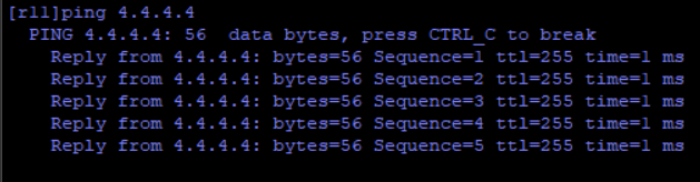
配置NAT环境,完成所有设备均可访问R4的环回
[R3]acl 2000
[R3-acl-basic-2000]rule permit source 172.16.0.0 0.0.255.255
[R3-acl-basic-2000]q
[R3]int Serial 4/0/0
[R3-Serial4/0/0]nat outbound 2000

[R7]acl 2000
[R7-acl-basic-2000]rule permit source 172.16.0.0 0.0.255.255
[R7-acl-basic-2000]q
[R7]int g 0/0/0
[R7-GigabitEthernet0/0/0]nat outbound 2000

[R6]acl 2000
[R6-acl-basic-2000]rule permit source 172.16.0.0 0.0.255.255
[R6-acl-basic-2000]q
[R6]int s 4/0/0
[R6-Serial4/0/0]nat outbound 2000
加快收敛
减少计时器时间
[R5]int t 0/0/0
[R5-Tunnel0/0/0]ospf timer hello 5

[R3]int t 0/0/0
[R3-Tunnel0/0/0]ospf timer hello 5

[R6]int t 0/0/0
[R6-Tunnel0/0/0]ospf timer hello 5

[R7]int t 0/0/0
[R7-Tunnel0/0/0]ospf timer hello 5
保障更新安全
进行手工认证,采用区域认证(实际上也是接口认证)
[R2]ospf 1
[R2-ospf-1]area 1
[R2-ospf-1-area-0.0.0.1]authentication-mode md5 1 cipher 123456

[R1]ospf 1
[R1-ospf-1]area 1
[R1-ospf-1-area-0.0.0.1]authentication-mode md5 1 123456

[R3]ospf 1
[R3-ospf-1]area 1
[R3-ospf-1-area-0.0.0.1]authentication-mode md5 1 cipher 123456
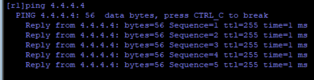
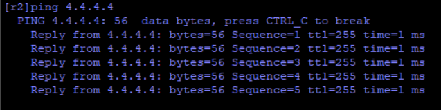
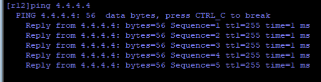
测试全网可达:


 162
162


 被折叠的 条评论
为什么被折叠?
被折叠的 条评论
为什么被折叠?
 到【灌水乐园】发言


