FDTD Script 远场图-farfield3dintegrate/farfieldspherical

FDTD Script命令学习-farfield3dintegrate/farfieldspherical


 本文介绍了FDTD仿真中的两个关键命令:farfield3dintegrate用于在锥形区域内对3D远场投影数据进行积分,而farfieldspherical则将远场数据转换为球坐标系。这两个命令涉及的角度参数以度为单位但在计算中转换为弧度。示例代码展示了如何使用这些命令来计算特定锥形区域内的能量比例以及生成球坐标系下的电场分布图像。
摘要由CSDN通过智能技术生成
目录

一、farfield3dintegrate命令介绍
(1)语法
(2)示例
二、farfieldspherical命令介绍
(1)语法

(2)示例

一、参考FDTD官网farfield3dintegrate命令介绍:

https://optics.ansys.com/hc/en-us/articles/360034410174-farfield3dintegrate-Script-command

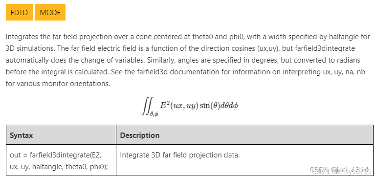
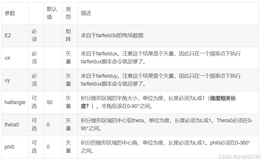
1. farfield3dintegrate命令功能:在3D模拟中,在以立体角theta0(与z轴的夹角)和方位角phi0(与x轴的夹角) 为中心、在指定的半角宽度的锥形区域下的远场投影积分。远场电场是方向余弦(ux,uy)的函数,但是farfileld3dintegrate会自动对变量进行变更(根据下一句话,应该是进行单位换算)。类似的,角度是指定以度为单位,但是进行积分计算前会转化为弧度。不同监视器取向ux,uy,na,nb的介绍可以参考farfield3d命令介绍。

(1)语法:out=farfield3dintegrate(E2,ux,uy,halfangle,theta0,phi0);见上述积分公式,该语法是对3D远场投影数据的积分。


(2)示例

计算光源达到中心角theta=phi=0,30°的锥形远场区域的能量比例。

代码如下:
m="monitor1"; 
res = 201;
E2 = farfield3d(m,1,res,res); #返回远场投影的电场强度数据,结果为201*201阶矩阵;
ux = farfieldux(m,1,res,res);#返回结果为201*201阶矩阵,方向矢量;
uy = farfielduy(m,1,res,res);
halfangle=30;#半角大小为30°
theta0=0;
phi0=0;
cone_30 = farfield3dintegrate(E2, ux, uy, halfangle, theta0, phi0); # integrate over 30 degree cone,采用上述公式进行积分计算;
total = farfield3dintegrate(E2, ux, uy); # integrate over entire hemisphere,对半角大小为90°的半球电场强度进行积分计算;
T   = transmission(m); # fraction of source power transmitted into far field,返回监视器monitor1中的透过率数据;
?cone_30/total;  # fraction of far field power within a 30 degree cone,显示投影到远场中半角大小为30°电场强度与整个半球远场区域的电场强度比例;
?cone_30/total*T; # fraction of source power transmitted into the far field within a 30 degree cone,显示投影到远场中半角大小为30°电场强度与整个光源的强度比例;
附:transmission命令可以参考:https://optics.ansys.com/hc/en-us/articles/360034405354-transmission-Script-command

二、参考FDTD官网farfieldspherical命令介绍:

https://optics.ansys.com/hc/en-us/articles/360034410194-farfieldspherical-Script-command

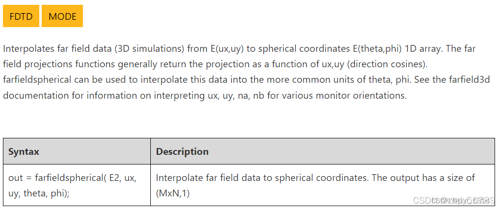
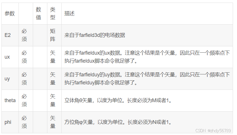
 1. farfieldspherical命令功能:将3D模拟的远场电场E(ux,uy)数据转换到球坐标系下一位阵列的电场E(theta,phi)中。远场投影函数一般会返回关于ux,uy(方向余弦)函数的投影。farfieldspherical用来将这个远场投影数据转化为到更加普遍的theta,phi单位中(功能即坐标系的转化:三维笛卡尔坐标系转换为球坐标系)。不同监视器取向ux,uy,na,nb的介绍可以参考farfield3d命令介绍。

(1)语法:out=farfieldspherical(E2,ux,uy,theta,phi);将远场数据转化为球坐标系下的数据。输出结果为维度为(M*N,1)(其中M和N分别为nb和na的投影分辨率);

(2)示例1:生成E2_far关于立体角theta的图片,方位角phi=0;

代码如下:

m="Monitor1";  # Monitor name
res = 201;    # projection resolution
E2 = farfield3d(m,1,res,res);
ux = farfieldux(m,1,res,res);
uy = farfielduy(m,1,res,res);
theta = linspace(-90,90,100); #theta角取值范围[-90,90],等间隔取100个点位
phi = 0;
plot(theta, farfieldspherical(E2,ux,uy,theta,phi) ,"theta", "E^2", "E^2 at phi=0");#以theta为x轴,farfieldspherical为轴,"theta"为x轴名称,“E^2”为y轴名称,“E^2 at phi=0”为图片名称,进行作图
示例2:将厂数据转化为以theta和phi角网格坐标系下。

代码如下:

theta = linspace(-90,90,10);
phi = linspace(0,45,11);
Theta = meshgridx(theta,phi); #将theta数据转化为11*10阶矩阵,其中矩阵中每行数据中元素为原始theta矩阵中的元素,且每行元素均相同
Phi = meshgridy(theta,phi);#将phi数据转化为11*10阶矩阵
E2_angle = farfieldspherical(E2,ux,uy,Theta,Phi);
E2_angle = reshape(E2_angle, [length(theta), length(phi)]);#将E2_angle矩阵11*10转换为10*11阶矩阵
image(theta, phi, E2_angle, "theta","phi","E2");#以theta为x轴,phi为y轴,对z进行作图,“theta”为x轴名称,“phi”为y轴名称,“E2”为图片名称
(3)其它参考

List of commands , farfield3d , farfieldux , farfielduy , Far field projections - Direction unit vector coordinates , meshgridx , meshgridy;
————————————————

                            版权声明:本文为博主原创文章,遵循 CC 4.0 BY-SA 版权协议,转载请附上原文出处链接和本声明。
                        
原文链接:https://blog.csdn.net/jxxl_1314/article/details/130329297

FDTD软件英文使用说明 Initial Properties dialog box ................................................................................... 33 Mask Export............................................................................................................. 41 Profile Designer....................................................................................................... 42 Wafer Properties ..................................................................................................... 42 Profiles In Use ......................................................................................................... 44 Properties ................................................................................................................ 45 Toolbars ................................................................................................................... 45 Status bar................................................................................................................. 45 Color Spectrum ....................................................................................................... 46 Workbook Mode ...................................................................................................... 49 3D Graph Items........................................................................................................ 50 Show slice selector................................................................................................. 54 Refractive Index (X, Y, and Z directions) .............................................................. 54 Zoom tool................................................................................................................. 54 Edit Parameters....................................................................................................... 56 2D Simulation Parameters...................................................................................... 62 3D Simulation Parameters...................................................................................... 66 3D Simulation Parameters for 64-bit simulator .................................................... 68 2D Band Solver Parameters ................................................................................... 73 PWE Band Solver .................................................................................................... 78 Test Script................................................................................................................ 86 Run Script (2D or 3D).............................................................................................. 86 Generate Template Script....................................................................................... 86 Generate Layout Script........................................................................................... 86 Generate Scanning Script ...................................................................................... 86 Preferences menu ................................................................................................... 87 Edit Menu ................................................................................................................. 89 3D Objects ...................................................................................................... 93 Common elements of 3D object waveguides ....................................................... 94 Clipping Planes ..................................................................................................... 103 Profile Designer ........................................................................................... 107 Main parts of the GUI ............................................................................................ 108 Main menu bar....................................................................................................... 112 Toolbars ................................................................................................................. 112 Library Browser toolbar ....................................................................................... 113 Profile toolbar........................................................................................................ 114Table of Contents Installing OptiFDTD ......................................................................................... 1 Hardware and software requirements..................................................................... 1 Protection key ........................................................................................................... 2 Installation ................................................................................................................. 2 Technical support ..................................................................................................... 3 Overview........................................................................................................... 5 What is OptiFDTD? ................................................................................................... 5 OptiFDTD applications and how they relate to one another................................. 6 OptiFDTD_Designer .................................................................................................. 6 Main elements of a layout design............................................................................ 8 What’s new in OptiFDTD 8.0 ......................................................................... 11 64-bit 2D Simulator ................................................................................................. 11 Heating Absorption................................................................................................. 13 Total Field Scattering Field 2D simulations and analysis ................................... 13 OptiFDTD_Designer....................................................................................... 17 Main parts of the GUI .............................................................................................. 18 Main menu bar......................................................................................................... 22 Toolbars ................................................................................................................... 22 OptiFDTD_Designer menus and buttons..................................................... 23 File menu ................................................................................................................. 23 Edit menu................................................................................................................. 24 View menu ............................................................................................................... 25 Tools menu .............................................................................................................. 27 Draw menu............................................................................................................... 27 Simulation menu ..................................................................................................... 31 Preferences menu ................................................................................................... 31 Window menu.......................................................................................................... 32 Help menu................................................................................................................ 32 OptiFDTD_Designer functions...................................................................... 33OptiBPM Specific Materials ........................................................................ 169 Material Class ........................................................................................................ 169 Create and edit materials ..................................................................................... 169 Dielectric material (Ordinary)............................................................................... 170 Diffused material ................................................................................................... 173 OptiFDTD Specific Materials....................................................................... 177 Material Class ........................................................................................................ 177 Create and edit materials ..................................................................................... 177 Dielectric ................................................................................................................ 178 Dispersion.............................................................................................................. 183 Converting the ‘Sellmeier equation’ to ‘Lorentz Model’ .................................... 184 Nonlinear................................................................................................................ 192 Perfect Conductor................................................................................................. 196 2D Band Solver ............................................................................................ 199 2D Band Solver Parameters ................................................................................. 199 File menu ............................................................................................................... 201 Simulation menu ................................................................................................... 201 View menu ............................................................................................................. 201 Help menu.............................................................................................................. 202 Waveguides.................................................................................................. 205 Waveguide properties........................................................................................... 205 Waveguide profiles ............................................................................................... 205 Wafer ...................................................................................................................... 208 Waveguide vs. wafer............................................................................................. 209 Initial data .............................................................................................................. 211 Local Coordinate System ..................................................................................... 211 User Interface of a Parameterized position of a Layout Shape ........................ 212 Waveguides ........................................................................................................... 214 Linear ..................................................................................................................... 216 Arc .......................................................................................................................... 222 Elliptic .................................................................................................................... 228 Ring ........................................................................................................................ 233 S-Bend Sines ......................................................................................................... 239 S-Bend Arc............................................................................................................. 239 S-Bend Sine ........................................................................................................... 244S-Bend Cosine....................................................................................................... 250 Linear Taper........................................................................................................... 256 Parabolic Taper ..................................................................................................... 262 Exponential Taper ................................................................................................. 267 S-Bend Arc Taper.................................................................................................. 273 S-Bend Sine Taper ................................................................................................ 278 S-Bend Cosine Taper............................................................................................ 285 Circular Lens ......................................................................................................... 291 Elliptic Lens ........................................................................................................... 296 Parabolic Lens....................................................................................................... 303 Hyperbolic Lens .................................................................................................... 309 Polynomial ............................................................................................................. 315 Photonic Band Gap (PBG) Crystal Structure ..................................................... 321 Basic 3D Linear Tapering and Proportional Interpretation of Fiber Profile..... 330 Input Field..................................................................................................... 339 Input Field vs. Input Plane.................................................................................... 339 Insert an input plane ............................................................................................. 340 Input Field dialog box ........................................................................................... 343 Mode—Global Data: ADI Method ......................................................................... 359 Mode Solver 2D ..................................................................................................... 379 Mode Solver 2D—menus ...................................................................................... 380 Mode Solver 2D—tabs .......................................................................................... 396 TFSF Region Properties ....................................................................................... 401 3D Mode Solver............................................................................................ 407 Main parts of the GUI ............................................................................................ 410 Main menu bar....................................................................................................... 414 Toolbars ................................................................................................................. 414 3D Mode Solver menus and buttons.......................................................... 417 File menu ............................................................................................................... 417 View menu ............................................................................................................. 417 Simulation menu ................................................................................................... 419 Data menu.............................................................................................................. 419 Preferences menu ................................................................................................. 420 Help menu.............................................................................................................. 420 3D Mode Solver functions........................................................................... 421Profile Designer menus............................................................................... 117 File menu ............................................................................................................... 117 View menu ............................................................................................................. 117 Tools menu ............................................................................................................ 117 Help menu.............................................................................................................. 117 Profile Designer context menu ............................................................................ 118 Profile Designer functions .......................................................................... 119 Library Browser..................................................................................................... 119 Compare Libraries ................................................................................................ 119 Edit Variables and Functions............................................................................... 122 Mode—Global Data: ADI Method ......................................................................... 123 Mode Settings........................................................................................................ 124 Options................................................................................................................... 125 Profiles.......................................................................................................... 127 Fiber ....................................................................................................................... 127 Channel .................................................................................................................. 131 OptiBPM Specific Diffused Materials ......................................................... 137 Custom Diffusion Processes and Arbitrary Index Profiles ............................... 137 Diffusion Process Library .................................................................................... 137 Ti:LiNb03 profile - Titanium diffusion in lithium niobate................................... 138 Ti:LiNbO 3 Pro toolbar ........................................................................................... 139 Mg:LiNb03 profile - Magnesium diffusion in lithium niobate............................ 143 Mg:LiNb0 3 Pro toolbar .......................................................................................... 144 Proton Exchange profile - H+:LiNb03.................................................................. 148 Proton Exchange toolbar ..................................................................................... 149 Annealing Process................................................................................................ 151 OptiBPM Specific User Function Profile.................................................... 153 OptiBPM Specific User DLL Profile............................................................ 159 Center point ........................................................................................................... 162 Materials ....................................................................................................... 167Mode Found........................................................................................................... 421 Status Bar .............................................................................................................. 422 3D Graph Items...................................................................................................... 422 Show slice selector............................................................................................... 426 Customize .............................................................................................................. 426 Data menu.............................................................................................................. 429 3D Graph Settings................................................................................................. 432 Layout Options...................................................................................................... 441 Observation Points, Areas, and Lines ....................................................... 445 Observation Point ................................................................................................. 445 Observation Area .................................................................................................. 445 Observation Line................................................................................................... 446 Simulation toolbar................................................................................................. 446 Observation Points...................................................................................... 447 Observation properties—Point dialog box ......................................................... 448 Observation Area......................................................................................... 451 Observation properties -- X-Z Area dialog box .................................................. 452 Observation properties -- Y-Z Area dialog box .................................................. 455 Observation properties -- X-Y Area dialog box .................................................. 457 Observation Area Analysis dialog box ............................................................... 459 Observation Line.......................................................................................... 474 Observation properties -- Vertical Line dialog box............................................ 475 OptiFDTD_Simulator (2D)............................................................................ 479 Main parts of the GUI ............................................................................................ 480 Main menu bar....................................................................................................... 483 Toolbars ................................................................................................................. 483 OptiFDTD_Simulator (2D) menus and buttons ......................................... 485 File menu ............................................................................................................... 485 View menu ............................................................................................................. 485 Simulation menu ................................................................................................... 487 Preferences menu ................................................................................................. 489Export..................................................................................................................... 597 3D Graph Items...................................................................................................... 598 Simulation menu ................................................................................................... 598 Components menu................................................................................................ 601 Preferences menu ................................................................................................. 601 OptiFDTD Tools............................................................................................ 605 Overlap Integral............................................................................................ 607 Gaussian Overlap Scanner ......................................................................... 615 Overlap Integral Scanner ............................................................................ 619 Multiple Fields .............................................................................................. 623 Notes ...................................................................................................................... 628 Multiple Gaussians ...................................................................................... 629 Notes ...................................................................................................................... 632 Confinement Factor ..................................................................................... 633 Notes ...................................................................................................................... 638 Far Field........................................................................................................ 639 Fraunhofer approximation ................................................................................... 639 Fresnel-Kirchhoff Diffraction Formula ................................................................ 640 2D Far Field............................................................................................................ 641 3D Far Field............................................................................................................ 643 References............................................................................................................. 645 Mode 2D........................................................................................................ 647 Modes of Planar Waveguides .............................................................................. 649 File menu ............................................................................................................... 650 Edit menu............................................................................................................... 650 View menu ............................................................................................................. 651 Simulation menu ................................................................................................... 651 Window menu........................................................................................................ 651Help menu.............................................................................................................. 489 Simulation Parameters ......................................................................................... 490 Boundary Conditions............................................................................................ 491 Observation Point ................................................................................................. 492 Finalization ............................................................................................................ 494 OptiFDTD_Simulator (2D) functions .......................................................... 495 View list.................................................................................................................. 495 Status bar............................................................................................................... 496 3D Graph settings ................................................................................................. 501 OptiFDTD_Simulator (3D)............................................................................ 513 Main parts of the GUI ............................................................................................ 514 Main menu bar....................................................................................................... 517 Toolbars ................................................................................................................. 517 OptiFDTD_Simulator (3D) menus and buttons ......................................... 519 File menu ............................................................................................................... 519 View menu ............................................................................................................. 519 Simulation menu ................................................................................................... 522 Preferences menu ................................................................................................. 523 Help menu.............................................................................................................. 523 Simulation Parameters ......................................................................................... 524 Boundary Conditions............................................................................................ 525 Finalization ............................................................................................................ 527 OptiFDTD_Simulator (3D) functions .......................................................... 529 View list.................................................................................................................. 529 Status bar............................................................................................................... 530 3D Graph settings ................................................................................................. 535 PWE Band Solver......................................................................................... 545 OptiFDTD_Analyzer (2D Simulations)........................................................ 553 Main parts of the GUI ............................................................................................ 554 Components .......................................................................................................... 556 Main menu bar....................................................................................................... 559Toolbars ................................................................................................................. 559 OptiFDTD_Analyzer menus and buttons (2D Simulations)...................... 561 File menu ............................................................................................................... 561 View menu ............................................................................................................. 562 Components menu................................................................................................ 563 Simulation menu ................................................................................................... 564 Preferences menu ................................................................................................. 564 Tools menu ............................................................................................................ 564 Window menu........................................................................................................ 565 Help menu.............................................................................................................. 565 OptiFDTD_Analyzer functions (2D Simulations)....................................... 567 Export..................................................................................................................... 567 3D Graph Items...................................................................................................... 568 Components menu................................................................................................ 568 Simulation menu ................................................................................................... 568 Preferences menu ................................................................................................. 571 Tools menu ............................................................................................................ 571 OptiFDTD_Analyzer (3D Simulations)........................................................ 575 Main parts of the GUI ............................................................................................ 576 Main menu bar....................................................................................................... 580 Toolbars ................................................................................................................. 580 OptiFDTD_Analyzer menus and buttons (3D simulations) ...................... 581 File menu ............................................................................................................... 581 View menu ............................................................................................................. 582 Components menu................................................................................................ 583 Simulation menu ................................................................................................... 584 Preferences menu ................................................................................................. 584 Tools menu ............................................................................................................ 584 Window menu........................................................................................................ 585 Help menu.............................................................................................................. 585 OptiFDTD_Analyzer functions (3D simulations) ....................................... 587 Analysis Tools....................................................................................................... 587Code V Converter......................................................................................... 727 Data format ............................................................................................................ 729 EXFO OWA Converter ................................................................................. 731 Zemax Converter.......................................................................................... 739 Conversion ............................................................................................................ 739 Notes on Conversion ............................................................................................ 740 Data formats .......................................................................................................... 741 ZEMAX Beam File (ZBF) binary format ............................................................... 741 Appendix A: Opti2D Graph Control............................................................ 743 User interface features ......................................................................................... 744 Graph Properties dialog ....................................................................................... 754 Appendix B: File formats ............................................................................ 763 Data file formats .................................................................................................... 763 Appendix C: Parser supported functions.................................................. 773 Supported functions ............................................................................................. 773 Function Limits and _FnRslt_.............................................................................. 778 Appendix D: Batch processing................................................................... 781 Automatic loading of VB Script from command line ......................................... 785Simulation functions............................................................................................. 652 Correlation Function Method (CFM).................................................................... 660 File menu ............................................................................................................... 661 Edit menu............................................................................................................... 661 View menu ............................................................................................................. 662 Simulation menu ................................................................................................... 662 Window menu........................................................................................................ 662 Simulation functions............................................................................................. 663 User Defined File................................................................................................... 672 File menu ............................................................................................................... 673 Edit menu............................................................................................................... 674 View menu ............................................................................................................. 674 Simulation menu ................................................................................................... 674 Window menu........................................................................................................ 674 Notes: ..................................................................................................................... 676 Mode 3D........................................................................................................ 677 File menu ............................................................................................................... 677 Edit menu............................................................................................................... 678 View menu ............................................................................................................. 678 Operations menu................................................................................................... 680 Simulation menu ................................................................................................... 680 Draw Tool menu .................................................................................................... 681 Preferences menu ................................................................................................. 681 Layout Designer Dialog boxes of Mode Solver 3D ............................................ 683 Layout Settings layout dialog box....................................................................... 702 Waveguide Colors layout dialog box .................................................................. 703 Notes: ..................................................................................................................... 704 User Guide of View 3D................................................................................. 705 Commands of View 3D ......................................................................................... 705 View menu ............................................................................................................. 707 Toolbars menu ...................................................................................................... 707 Status Bar menu.................................................................................................... 708 Settings menu ....................................................................................................... 711 Dialog boxes of View 3D....................................................................................... 713 Notes: ..................................................................................................................... 726
评论
添加红包

请填写红包祝福语或标题

红包个数最小为10个

红包金额最低5元

当前余额3.43前往充值 >
需支付:10.00
成就一亿技术人!
领取后你会自动成为博主和红包主的粉丝 规则
hope_wisdom
发出的红包
实付
使用余额支付
点击重新获取
扫码支付
钱包余额 0

抵扣说明:

1.余额是钱包充值的虚拟货币,按照1:1的比例进行支付金额的抵扣。
2.余额无法直接购买下载,可以购买VIP、付费专栏及课程。

余额充值