


一.SD卡简介
1) 简介:
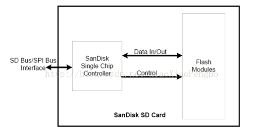
SD卡是基于flash的存储卡。
SD卡和MMC卡的区别在于初始化过程不同。
SD卡的通信协议包括SD和SPI两类。
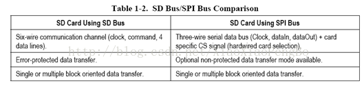
SD卡使用卡内智能控制模块进行FLASH操作控制,包括协议、安全算法、数据存取、ECC算法、缺陷处理和分析、电源管理、时钟管理。
2) 类型:
MMC卡: MultiMedia card,有 7个触点(引脚),分为两种操作模式,分别为MMC模式与SPI模式,两种模式对引脚的定义是不同的。SPI模式只有 Host 具有SPI接口时才能使用。MMC只具有存储功能,不像SD卡还具有加密功能。
SD卡: Security Digtial card,共有9个触点(引脚),多余的 2 个引脚为数据线,但使用与MMC卡兼容的模式时,这两个多余的引脚没有起到作用。SD卡除了存储功能外,还有一种加密功能,但加密功能是收费的(所以开源的linux中只包含mmc的驱动目录),因为当初SD卡联盟中(索尼)就是发明这种卡就是用来存储音乐(淘汰卡带),并使用加密特性,防止拷贝。
TF卡:软件上SD卡一致,只是在硬件的体积上比SD卡西小,所以市场上很多的TF卡的SD外形卡套
3) 协议:
1.x:小于2GB的卡(但通过相关的软件,可以模拟实现大于2GB)
2.0: 2<SD卡<32 GB
3.0: >32GB
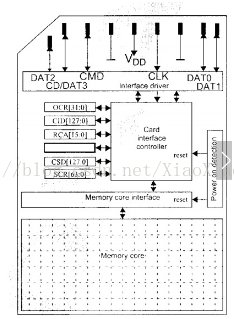
二.SD卡引脚介绍
SD卡结构
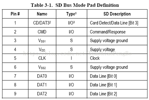
1) SD卡模式下引脚介绍
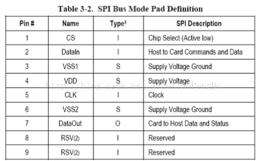
2) SPI模式引脚介绍
三.SD卡寄存器介绍
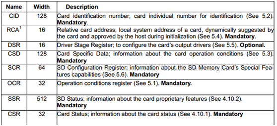
1) CID:The Card IDentification (CID) register is 128 bits wide. It containsthe card identification information used during the card identification phase.Every individual Read/Write (RW) card shall have a unique identificationnumber. The structure of the CID register is defined in the followingparagraphs:
其中就不一一介绍,主要包含一些SD卡的信息
2) RCA:The writable 16-bit relative card address register carries the cardaddress that is published by the card during the card identification. Thisaddress is usedfor the addressed host-card communication after the cardidentification procedure. The default value of the RCA register is 0x0000. Thevalue 0x0000 is
reserved to set all cards into the Stand-by Statewith CMD7.
3) DSR:The 16-bit driver stage register is described in detail inChapter 6.5. It can be optionally used to improve the bus performance forextended operating conditions (depending on parameters like bus length,transfer rate or number of cards). The CSD register carries the informationabout the DSR register usage. The default value of the DSR register is 0x404.
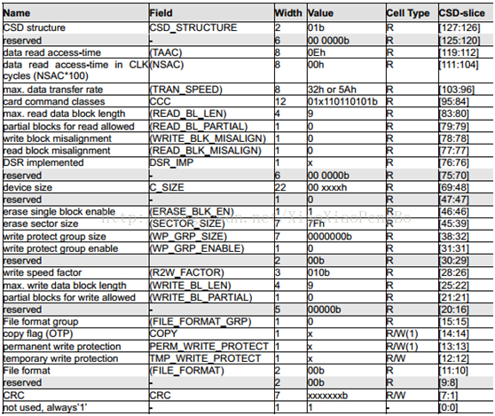
4) CSD:Table hows Definition of the CSD for the High Capacity SD MemoryCard (CSD Version 2.0). The following sections describe the CSD fields and therelevant data types for the High Capacity SD Memory Card.
CSD Version 2.0 is applied to only the High Capacity SDMemory Card. The field name in parenthesis is set to fixed value and indicatesthat the host is not necessary to refer these fields. The fixed values enableshost, which refers to these fields, to keep compatibility to CSD Version 1.0.The Cell Type field is coded as follows: R = readable, W(1) = writable once, W= multiple writable.
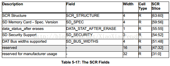
5) SCR:In addition to the CSD register, there is another configurationregister named SD CARD Configuration Register (SCR). SCR provides informationon the SD Memory Card's special features that were configured into the givencard. The size of SCR register is 64 bits. This register shall be set in thefactory by the SD Memory Card manufacturer.
The following table describes the SCR register content.
6) OCR
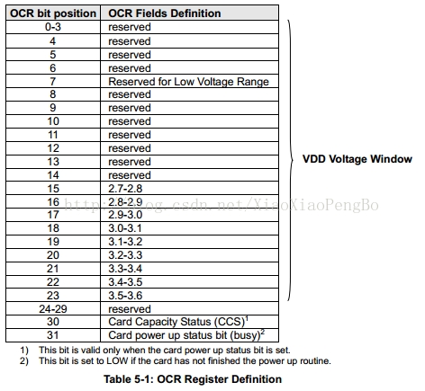
The 32-bit operation conditions register stores theVDDvoltage profile of the card. Additionally, this register includes statusinformation bits. One status bit is set if the card power up procedure has beenfinished. This register includes another status bit indicating the cardcapacity status after set power up status bit. The OCR register shall beimplemented by the cards.
The 32-bit operation conditions register stores theVDDvoltage profile of the card. Bit 7 of OCR is newly defined for Dual VoltageCard and set to 0 in default. If a Dual Voltage Card does not receive CMD8, OCRbit 7 in the response indicates 0, and the Dual Voltage Card which receivedCMD8, sets this bit to 1.
Additionally, this register includes 2 more status information bits.
Bit 31 - Card power up status bit, this status bit is setif the card power up procedure has been finished.
Bit 30 - Card capacity status bit, this status bit is setto 1 if card is High Capacity SD Memory Card. 0
indicates that the card is Standard Capacity SD MemoryCard. The Card Capacity status bit is valid after the card power up procedureis completed and the card power up status bit is set to 1. The Host shall readthis status bit to identify a Standard or High Capacity SD Memory Card. The OCRregister shall be implemented by the cards.
7) SSR:The SD Status contains status bits that are related to the SDMemory Card proprietary features and may be used for futureapplication-specific usage
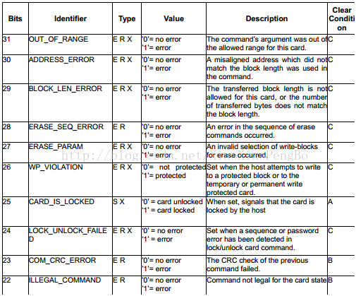
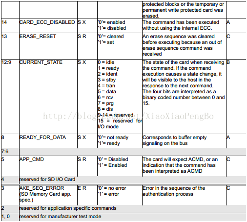
8) CSR:The response format R1 contains a 32-bit field named cardstatus. This field is intended to transmit the card’s status information (whichmay be stored in a local status register) to the host. If not specifiedotherwise, the status entries are always related to the previous issuedcommand.

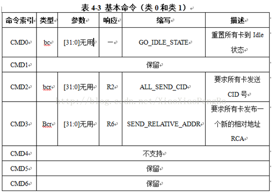
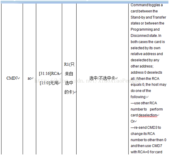
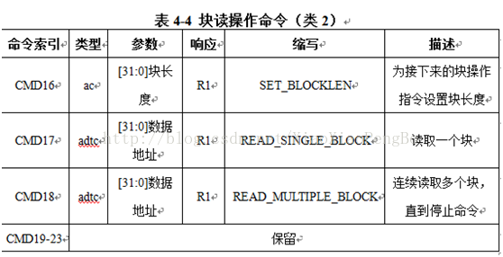
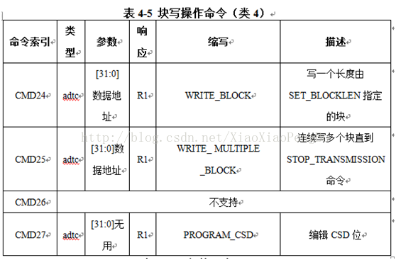
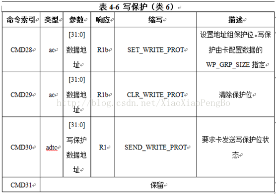
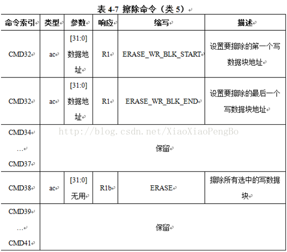
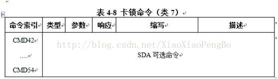
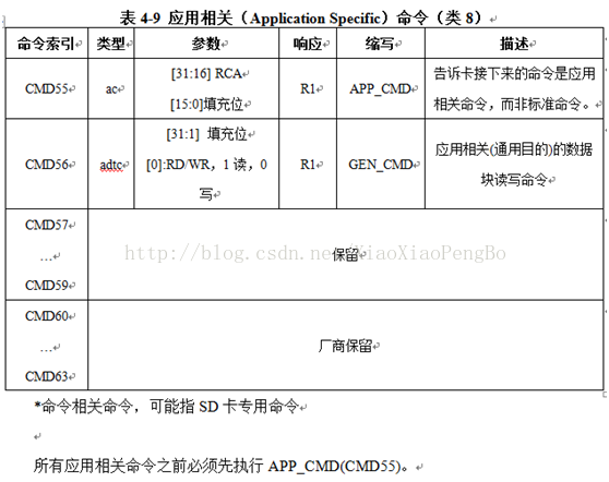
四.SD协议命令

五.命令响应
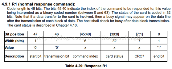
All responses are sent via the command line CMD. Theresponse transmission always starts with the left bit of the bit stringcorresponding to the response codeword. The code length depends on the responsetype.
A response always starts with a start bit (always 0),followed by the bit indicating the direction of transmission (card = 0). Avalue denoted by ‘x’ in the tables below indicates a variable entry. Allresponses except for the type R3 (see below) are protected by a CRC (seeChapter 4.5 for the definition of CRC7). Every command codeword is terminatedby the end bit (always 1). There are five types of responses for the SD MemoryCard. The SDIO Card supports additional response types named R4 and R5. Referto SDIO Card Spec for detailed information on the SDIO commands and responses.Their formats are defined as follows:
六.SD卡使用过程
SD卡初始化过程
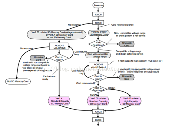
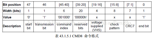
从图中,我们看到,不管什么卡(这里我们将卡分为4类:SD2.0高容量卡(SDHC,最大32G),SD2.0标准容量卡(SDSC,最大2G),SD1.x卡和MMC卡),首先我们要执行的是卡上电(需要设置SDIO_POWER[1:0]=11),上电后发送CMD0,对卡进行软复位,之后发送CMD8命令,用于区分SD卡2.0,只有2.0及以后的卡才支持CMD8命令,MMC卡和V1.x的卡,是不支持该命令的。CMD8的格式如表所示:
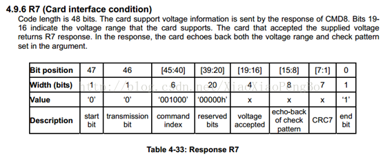
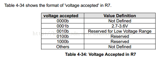
这里,我们需要在发送CMD8的时候,通过其带的参数我们可以设置VHS位,以告诉SD卡,主机的供电情况,VHS位定义如表所示
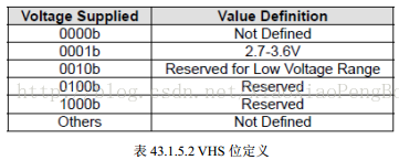
这里我们使用参数0X1AA,即告诉SD卡,主机供电为2.7~3.6V之间,如果SD卡支持CMD8,且支持
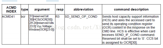
该电压范围,则会通过CMD8的响应(R7)将参数部分原本返回给主机,如果不支持CMD8,或者不支持这个电压范围,则不响应。在发送CMD8后,发送ACMD41(注意发送ACMD41之前要先发送CMD55),来进一步确认卡的操作电压范围,并通过HCS位来告诉SD卡,主机是不是支持高容量卡(SDHC)。
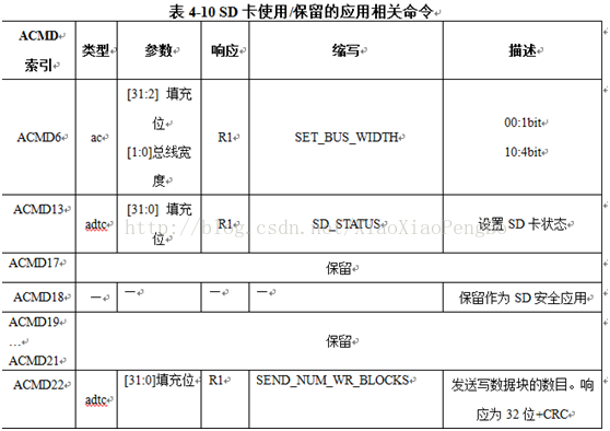
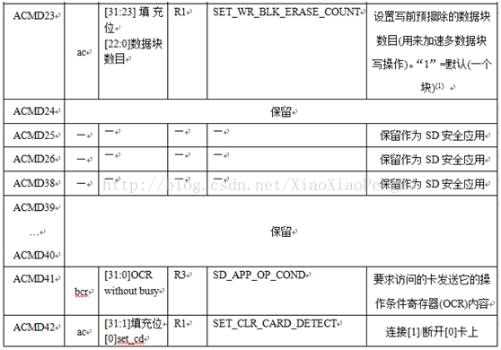
ACMD41的命令格式如表所示
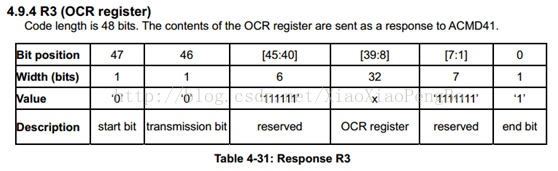
ACMD41得到的响应(R3)包含SD卡OCR寄存器内容,OCR寄存器内容定义如表所示:
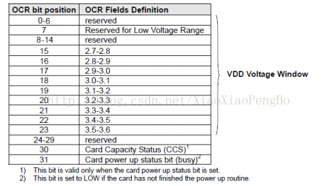
对于支持CMD8指令的卡,主机通过ACMD41的参数设置HCS位为1,来告诉SD卡主机支SDHC卡,如果设置为0,则表示主机不支持SDHC卡,SDHC卡如果接收到HCS为0,则永远不会反回卡就绪状态。对于不支持CMD8的卡,HCS位设置为0即可。
SD卡在接收到ACMD41后,返回OCR寄存器内容,如果是2.0的卡,主机可以通过判断OCR的CCS位来判断是SDHC还是SDSC;如果是1.x的卡,则忽略该位。OCR寄存器的最
后一个位用于告诉主机SD卡是否上电完成,如果上电完成,该位将会被置1。
对于MMC卡,则不支持ACMD41,不响应CMD55,对MMC卡,我们只需要在发送CMD0后,在发送CMD1(作用同ACMD41),检查MMC卡的OCR寄存器,实现MMC卡的初始化。
至此,我们便实现了对SD卡的类型区分,图中,最后发送了CMD2和CMD3命令,用于获得卡CID寄存器数据和卡相对地址(RCA)。
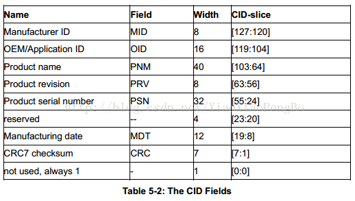
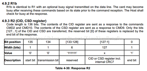
CMD2,用于获得CID寄存器的数据,CID寄存器数据各位定义如表所示:
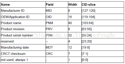
SD卡在收到CMD2后,将返回R2长响应(136位),其中包含128位有效数据(CID寄
存器内容),存放在SDIO_RESP1~4等4个寄存器里面。通过读取这四个寄存器,就可以获得
SD卡的CID信息。
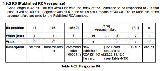
CMD3,用于设置卡相对地址(RCA,必须为非0),对于SD卡(非MMC卡),在收到
CMD3后,将返回一个新的RCA给主机,方便主机寻址。RCA的存在允许一个SDIO接口挂
多个SD卡,通过RCA来区分主机要操作的是哪个卡。而对于MMC卡,则不是由SD卡自动
返回RCA,而是主机主动设置MMC卡的RCA,即通过CMD3带参数(高16位用于RCA设
置),实现RCA设置。同样MMC卡也支持一个SDIO接口挂多个MMC卡,不同于SD卡的
是所有的RCA都是由主机主动设置的,而SD卡的RCA则是SD卡发给主机的。
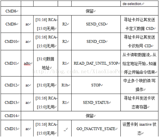
在获得卡RCA之后,我们便可以发送CMD9(带RCA参数),获得SD卡的CSD寄存器
内容,从CSD寄存器,我们可以得到SD卡的容量和扇区大小等十分重要的信息


 279
279

 被折叠的 条评论
为什么被折叠?
被折叠的 条评论
为什么被折叠?
 到【灌水乐园】发言


