


1.要求分析
-
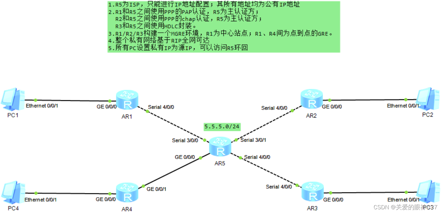
R5 为ISP,直连网段为公网IP,其余为私有网段
-
R1 和 R5 之间使用PPP协议的PAP认证,R5 为主认证方
-
R2 和 R5 之间使用PPP协议的CHAP认证,R5 为主认证方
-
R3 和 R5 之间使用HDLC协议封装
-
R1、R2、R3之间构建 MGRE 环境、R1为中心站点;R1、R4之间构建点到点的GRE环境
-
使用RIP获取路由·
-
私有地址要访问公有地址,所以在R1-R5上配置 NAT
2.步骤
(1)IP地址的配置
IP地址分配如下:

配置路由器、PC的IP及R5的环回:
[R1]int g 0/0/0
[R1-GigabitEthernet0/0/0]ip add 192.168.1.254 24
[R1-GigabitEthernet0/0/0]int s 4/0/0
[R1-Serial4/0/0]ip add 15.0.0.1 24

[R2]int g 0/0/0
[R2-GigabitEthernet0/0/0]ip add 192.168.2.254 24
[R2-GigabitEthernet0/0/0]int s 4/0/0
[R2-Serial4/0/0]ip add 25.0.0.1 24

[R3]int g 0/0/0
[R3-GigabitEthernet0/0/0]ip add 192.168.3.254 24
[R3-GigabitEthernet0/0/0]int s 4/0/0
[R3-Serial4/0/0]ip add 35.0.0.1 24

[R4]int g 0/0/1
[R4-GigabitEthernet0/0/1]ip add 45.0.0.1 24
[R4-GigabitEthernet0/0/1]int g 0/0/0
[R4-GigabitEthernet0/0/0]ip add 192.168.4.254 24

[R5]int s 3/0/0
[R5-Serial3/0/0]ip add 15.0.0.2 24
[R5-Serial3/0/0]int s 3/0/1
[R5-Serial3/0/1]ip add 25.0.0.2 24
[R5-Serial3/0/1]int s 4/0/0
[R5-Serial4/0/0]ip add 35.0.0.2 24
[R5-Serial4/0/0]int g 0/0/0
[R5-GigabitEthernet0/0/0]ip add 45.0.0.2 24
[R5-GigabitEthernet0/0/0]int l 0
[R5-LoopBack0]ip add 5.5.5.5 24
测试(例:用R5 ping 直连R1的接口):
(2)PAP认证
R1 和 R5 之间使用PPP协议的PAP认证,R5 为主认证方
R5配置:
[R5]aaa
[R5-aaa]local-user huawei password cipher 123456
[R5-aaa]local-user huawei service-type ppp
[R5-aaa]int s 3/0/0
[R5-Serial3/0/0]ppp authentication-mode papPPP会话的建立是一次性会话,会话建立完成后,后续的修改不会影响到会话本身,所以需要重新打开接口测试
[R5-Serial3/0/0]shutndown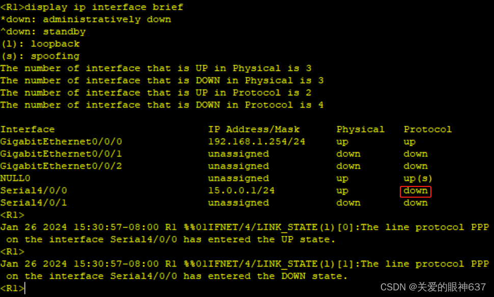
[R5-Serial3/0/0]undo shutdown因为此时只做了R5这一边的配置,查看此时R1的接口信息会发现接口的协议层面是down状态,此时是ping不通R5的直连接口的
 再做R1这边的配置:
R1配置:
[R1]int s 4/0/0
[R1-Serial4/0/0]ppp pap local-user huawei password cipher 123456
老样子,重新打开接口(原因跟上面一样):
[R1-Serial4/0/0]shutdown
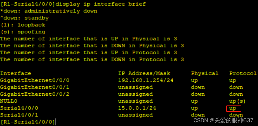
[R1-Serial4/0/0]undo shutdown再次查看R1的接口信息:
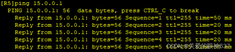
此时就能ping通了(R1 ping R5):

(3)CHAP认证
R2 和 R5 之间使用PPP协议封装的CHAP认证,R5 为主认证方
R5配置
[R5]aaa
[R5-aaa]local-user huawei2 password cipher 123456
[R5-aaa]local-user huawei2 service-type ppp
[R5-aaa]int s 3/0/1
[R5-Serial3/0/1]ppp authentication-mode chap
重新打开接口:
[R5-Serial3/0/1]shutndown
[R5-Serial3/0/1]undo shutdown
此时也是只做了R5这一边的配置,查看此时R2的接口信息:
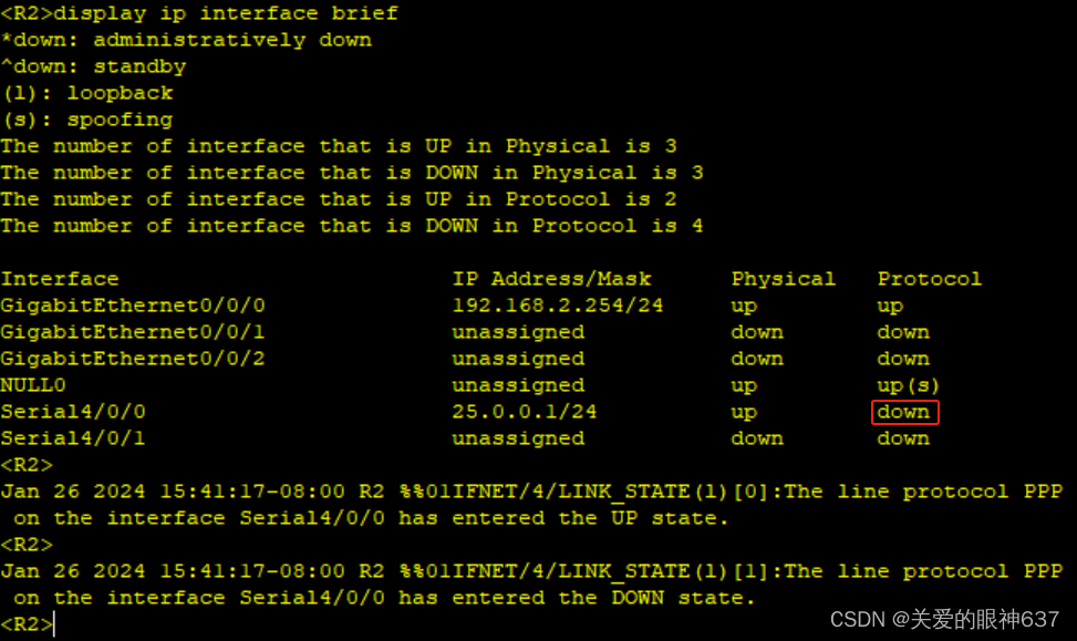
R2配置:
R2配置
[R2]int s 4/0/0
[R2-Serial4/0/0]ppp chap user huawei2
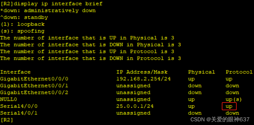
[R2-Serial4/0/0]ppp chap password cipher 123456重新打开接口:
[R2-Serial4/0/0]shutdown
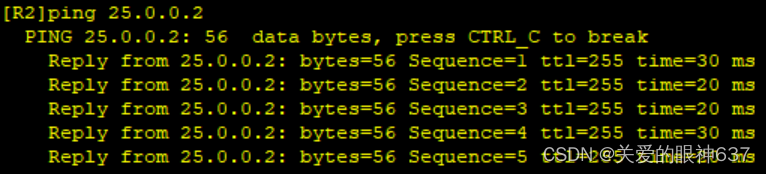
[R2-Serial4/0/0]undo shutdown再次查看R2的接口信息:
R2 ping R5 :
(4)HDLC协议封装
R3 和 R5 之间使用HDLC协议封装
华为设备串口默认使用的是ppp协议,所以将两端端口修改为HDLC协议即可
[R3]int s 4/0/0
[R3-Serial4/0/0]link-protocol hdlc
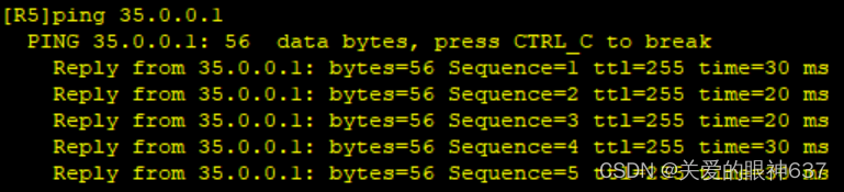
[R5]int s 4/0/0
[R5-Serial4/0/0]link-protocol hdlc测试:R5 ping R3(注意:仅修改一边,是无法ping通的)
(5)配置GRE环境
R1、R4之间构建点到点的GRE环境
定义该隧道网段为192.168.5.0/24,R1的隧道接口IP为192.168.5.1 、R4的隧道接口IP为192.168.5.4
[R1]int Tunnel 0/0/0
[R1-Tunnel0/0/0]ip add 192.168.5.1 24
[R1-Tunnel0/0/0]tunnel-protocol gre
[R1-Tunnel0/0/0]source 15.0.0.1
[R1-Tunnel0/0/0]destination 45.0.0.1

[R4]int Tunnel 0/0/0
[R4-Tunnel0/0/0]ip add 192.168.5.4 24
[R4-Tunnel0/0/0]tunnel-protocol gre
[R4-Tunnel0/0/0]source 45.0.0.1
[R4-Tunnel0/0/0]destination 15.0.0.1
(6)配置MGRE环境
R1、R2、R3之间构建 MGRE 环境,R1为NFS中心站点
定义该隧道网段为192.168.6.0/24,R1的隧道接口IP为192.168.6.1 、R2的隧道接口IP为192.168.6.2 、R3的隧道接口IP为192.168.6.3
R1配置
[R1]int t 0/0/1
[R1-Tunnel0/0/1]ip add 192.168.6.1 24
[R1-Tunnel0/0/1]tunnel-protocol gre p2mp
[R1-Tunnel0/0/1]source 15.0.0.1
[R1-Tunnel0/0/1]nhrp network-id 100

R2配置
[R2]int t 0/0/1
[R2-Tunnel0/0/1]ip add 192.168.6.2 24
[R2-Tunnel0/0/1]tunnel-protocol gre p2mp
[R2-Tunnel0/0/1]source Serial 4/0/0
[R2-Tunnel0/0/1]nhrp network-id 100
[R2-Tunnel0/0/1]nhrp entry 192.168.6.1 15.0.0.1 register

R3配置
[R3]int t 0/0/1
[R3-Tunnel0/0/1]ip add 192.168.6.3 24
[R3-Tunnel0/0/1]tunnel-protocol gre p2mp
[R3-Tunnel0/0/1]source s 4/0/0
[R3-Tunnel0/0/1]nhrp network-id 100
[R3-Tunnel0/0/1]nhrp entry 192.168.6.1 15.0.0.1 register
(7)开启RIP动态路由协议
需要宣告隧道接口网段
不宣告公网地址
写一条通往ISP的缺省
[R1]ip route-static 0.0.0.0 0 15.0.0.2
[R1]rip 1
[R1-rip-1]v 2
[R1-rip-1]undo summary
[R1-rip-1]network 192.168.1.0
[R1-rip-1]network 192.168.5.0
[R1-rip-1]network 192.168.6.0
[R1-rip-1]q
[R1]int t 0/0/1
[R1-Tunnel0/0/1]nhrp entry multicast dynamic //开启伪广播功能
[R1-Tunnel0/0/1]undo rip split-horizon //关闭水平分割机制

[R2]ip route-static 0.0.0.0 0 25.0.0.2
[R2]rip 1
[R2-rip-1]v 2
[R2-rip-1]undo summary
[R2-rip-1]network 192.168.2.0
[R2-rip-1]network 192.168.6.0

[R3]ip route-static 0.0.0.0 0 35.0.0.2
[R3]rip 1
[R3-rip-1]v 2
[R3-rip-1]undo summary
[R3-rip-1]network 192.168.3.0
[R3-rip-1]network 192.168.6.0

[R4]ip route-static 0.0.0.0 0 45.0.0.2
[R4]rip 1
[R4-rip-1]v 2
[R4-rip-1]undo summary
[R4-rip-1]network 192.168.4.0
[R4-rip-1]network 192.168.5.0
查看R2和R3的路由:
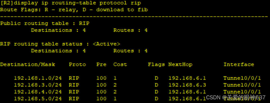

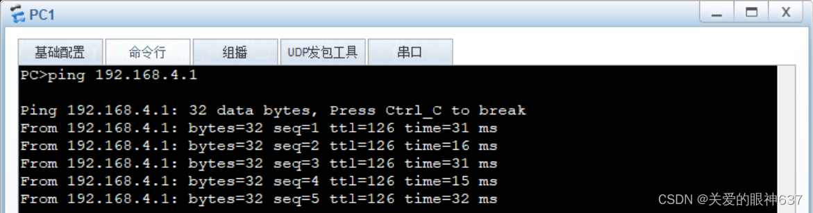
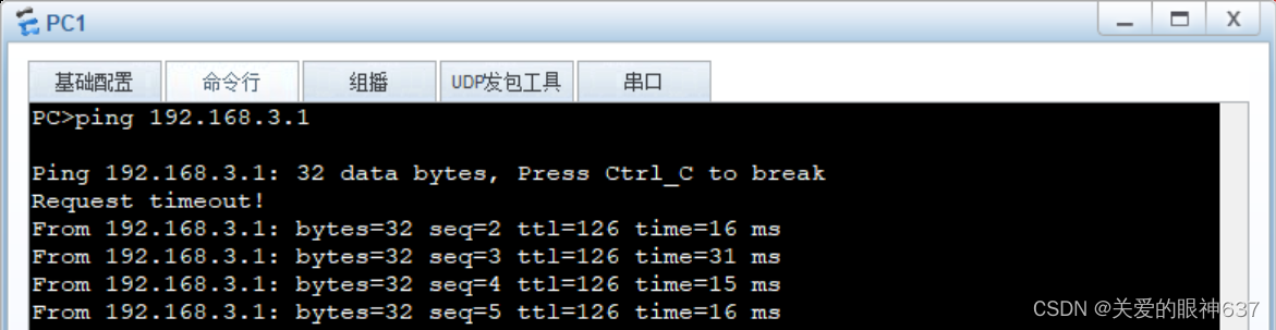
测试:
GRE:PC1 ping PC4
MGRE:PC1 ping PC2和PC3

(8)NAT配置
这里使用Eazy IP
[R1]acl 2000
[R1-acl-basic-2000]rule permit source 192.168.1.0 0.0.0.255  //抓流量
[R1-acl-basic-2000]q
[R1]int Serial 4/0/0
[R1-Serial4/0/0]nat outbound 2000  //调用acl2000

[R2]acl 2000
[R2-acl-basic-2000]rule permit source 192.168.2.0 0.0.0.255
[R2-acl-basic-2000]q
[R2]int s 4/0/0
[R2-Serial4/0/0]nat outbound 2000

[R3]acl 2000
[R3-acl-basic-2000]rule permit source 192.168.3.0 0.0.0.255
[R3-acl-basic-2000]q
[R3]int s 4/0/0
[R3-Serial4/0/0]nat outbound 2000

[R4]acl 2000
[R4-acl-basic-2000]rule permit source 192.168.4.0 0.0.0.255
[R4-acl-basic-2000]q
[R4]int g 0/0/1
[R4-GigabitEthernet0/0/1]nat outbound 2000
测试(例:用PC4 ping R5 环回):
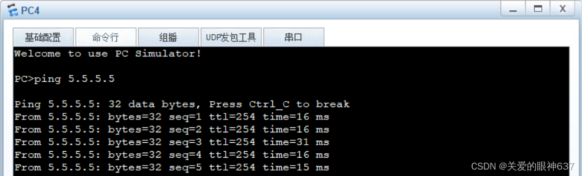
要求完成,试验结束。


 446
446


 被折叠的 条评论
为什么被折叠?
被折叠的 条评论
为什么被折叠?
 到【灌水乐园】发言


