


1.2.3:

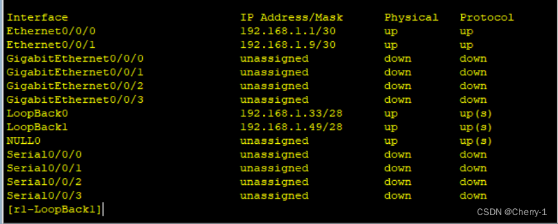
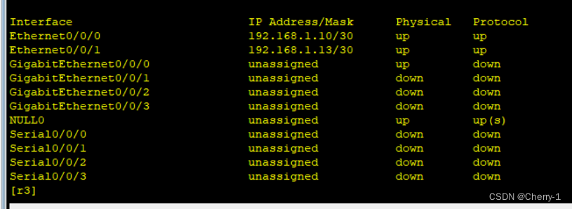
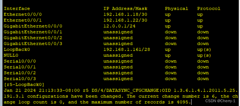
先给r1-r6分别配上ip地址以及换回地址:
r1:
r2:

r3:
r4:

r5:
r6:
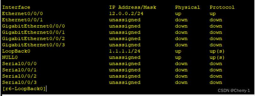
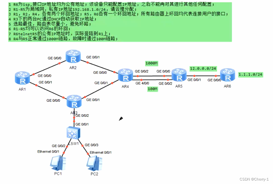
4.R3下的两台PC通过DHCP自动获取IP地址;
[r1]dhcp enable 先在设备上开启DHCP的服务
[r1]ip pool hh 创建dhcp池塘
[r1-ip-pool-hh]network network 192.168.1.96 mask 27 关联接口
[r1-ip-pool-wangcai]gateway-list 192.168.1.97 该网段的网关ip地址
[r1-ip-pool-wangcai]dns-list 8.8.8.8 DNS服务器地址
[r1]interface g0/0/0
[r1-GigabitEthernet0/0/0]dhcp select global


5.选路最佳,路由表尽量小,避免环路;
[r1]ip route-static 192.168.1.32 27 NULL0
[r2]ip route-static 192.168.1.64 27 NULL0
[r4]ip route-static 192.168.1.128 27 NULL0
6.R1-R5均可以访问R6的环回;
(配置静态路由:ip route-static 目标ip 子网掩码+下一跳)
(配置缺省路由:ip route-static 0.0.0.0 0+ip)
以下为静态路由:
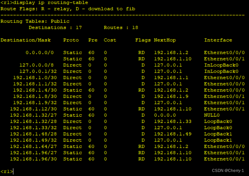
[R1]ip route-static 192.168.1.64 27 192.168.1.2
[R1]ip route-static 192.168.1.4 30 192.168.1.2
[R1]ip route-static 192.168.1.96 27 192.168.1.10
[R1]ip route-static 192.168.1.12 27 192.168.1.10
使用display ip routing-table查看如下:
[R2]ip route-static 192.168.1.32 27 192.168.1.1
[R2]ip route-static 192.168.1.8 30 192.168.1.1
[R2]ip route-static 192.168.1.96 27 192.168.1.1
[R2]ip route-static 192.168.1.96 27 192.168.1.6

[R3]ip route-static 192.168.1.32 27 192.168.1.9
[R3]ip route-static 192.168.1.0 30 192.168.1.9
[R3]ip route-static 192.168.1.64 27 192.168.1.9
[R3]ip route-static 192.168.1.64 27 192.168.1.14

[R4]ip route-static 192.168.1.32 27 192.168.1.5
[R4]ip route-static 192.168.1.32 27 192.168.1.13
[R4]ip route-static 192.168.1.0 30 192.168.1.5
[R4]ip route-static 192.168.1.8 30 192.168.1.13
[R4]ip route-static 192.168.1.64 27 192.168.1.5
[R4]ip route-static 192.168.1.96 27 192.168.1.13

[R5]ip route-static 192.168.1.32 27 192.168.1.17
[R5]ip route-static 192.168.1.64 27 192.168.1.17
[R5]ip route-static 192.168.1.96 27 192.168.1.17
[R5]ip route-static 192.168.1.0 30 192.168.1.17
[R5]ip route-static 192.168.1.4 30 192.168.1.17
[R5]ip route-static 192.168.1.8 30 192.168.1.17
[R5]ip route-static 192.168.1.12 30 192.168.1.17
[R5]ip route-static 192.168.1.128 27 192.168.1.17

以下为缺省路由:
-
[R1]ip route-static 0.0.0.0 0 192.168.1.2
-
[R1]ip route-static 0.0.0.0 0 192.168.1.10
-
[R2]ip route-static 0.0.0.0 0 192.168.1.6
-
[R3]ip route-static 0.0.0.0 0 192.168.1.14
-
[R4]ip route-static 0.0.0.0 0 192.168.1.18
-
[R4]ip route-static 0.0.0.0 0 192.168.1.22 preference 61改优先级
-
[R5]ip route-static 0.0.0.0 0 12.0.0.2
先使用ACL(标准列表即可),定义可被转换的私有ip地址范围
[r2]acl 2000
[r2-acl-basic-2000]rule permit source 192.168.1.0 0.0.0.255
然后再在边界路由器上,公有ip地址所在接口进行nat的配置即可
[r5]acl 2000
[r5-acl-basic-2000]rule permit source 192.168.1.0 0.0.0.255
[r5-acl-basic-2000]q
[r5]int g0/0/0
[r5-GigabitEthernet0/0/0]nat outbound 2000
以上完成后r1-r5即可访问r6网关了。
7.R6telnetR5的公有IP地址时,实际登陆到R1上;(端口映射:仅将一个公有ip地址的一个端口号,固定和一个私有ip地址的一个端口号进行转换)
先在r1上开启远程登录服务
[R1]aaa
[R1-aaa]local-user xj privilege level 2 password cipher 123456
[R1-aaa]local-user xj service-type telnet
[R1-aaa]q
[R1]user-interface vty 0 4
[R1-ui-vty0-4]authentication-mode aaa
将R5的g0/0/0的23口映射为R1的192.168.1.33的23口
[R5]interface g0/0/0
[R5-GigabitEthernet0/0/0]nat server protocol tcp global current-interface 23 inside 192.168.1.33 23
即可
8.R4与R5正常通过1000M链路,故障时通过100M链路;
[R5]ip route-static 192.168.1.0 255.255.255.252 192.168.1.21 permanent 61
[R5]ip route-static 192.168.1.4 255.255.255.252 192.168.1.21 permanent 61
[R5]ip route-static 192.168.1.8 255.255.255.252 192.168.1.21 permanent 61
[R5]ip route-static 192.168.1.12 255.255.255.252 192.168.1.21 permanent 61
[R5]ip route-static 192.168.1.32 255.255.255.224 192.168.1.21 permanent 61
[R5]ip route-static 192.168.1.64 255.255.255.224 192.168.1.21 permanent 61
[R5]ip route-static 192.168.1.96 255.255.255.224 192.168.1.21 permanent 61
[R5]ip route-static 192.168.1.128 255.255.255.224 192.168.1.21 permanent 61
[R5]ip route-static 192.168.1.128 255.255.255.224 192.168.1.21 permanent 61


 409
409


 被折叠的 条评论
为什么被折叠?
被折叠的 条评论
为什么被折叠?
 到【灌水乐园】发言


