


一、实验拓扑

二、实验步骤
1、R1、R2、R3、R4配置接口IP地址
R1:
[R1]int Ethernet0/0/0
[R1-Ethernet0/0/0]ip address 10.0.0.1 255.255.255.0
[R1-Ethernet0/0/0]int Ethernet0/0/1
[R1-Ethernet0/0/1]ip address 10.0.1.1 255.255.255.0
R2:
[R2]int Serial 0/0/0
[R2-Serial0/0/0]ip address 10.0.2.2 255.255.255.0
[R2]int Ethernet0/0/0
[R2-Ethernet0/0/0]ip address 10.0.1.2 255.255.255.0
[R2]int Ethernet0/0/1
[R2-Ethernet0/0/1]ip address 10.0.4.2 255.255.255.0
R3:
[R3]int Ethernet0/0/1
[R3-Ethernet0/0/1]ip address 10.0.3.3 255.255.255.0
[R3]int Serial 0/0/0
[R3-Serial0/0/0]ip address 10.0.2.3 255.255.255.0
R4:
[R4]int Ethernet0/0/0
[R4-Ethernet0/0/0]ip address 10.0.4.4 255.255.255.0
[R4-Ethernet0/0/0]int Ethernet0/0/1
[R4-Ethernet0/0/1]ip address 10.0.5.4 255.255.255.0
2、配置路由
R1:
[R1]ip route-static 0.0.0.0 0.0.0.0 10.0.1.2
命令行解释:由于R1去往其他任何网段下一跳地址都是10.0.1.2,所以目的地址和目的地址子网掩码采用任意地址0.0.0.0。
R2:
[R2]ip route-static 10.0.0.0 255.255.255.0 10.0.1.1
[R2]ip route-static 10.0.3.0 255.255.255.0 Serial 0/0/0
[R2]ip route-static 10.0.5.0 255.255.255.0 10.0.4.4
R3:
[R3]ip route-static 0.0.0.0 0.0.0.0 Serial 0/0/0
命令行解释:由于R3去往其他任何网段出接口都是Serial 0/0/0,所以目的地址和目的地址子网掩码采用任意地址0.0.0.0。
R4:
[R4]ip route-static 0.0.0.0 0.0.0.0 10.0.4.2
命令行解释:由于R1去往其他任何网段下一跳地址都是10.0.4.2,所以目的地址和目的地址子网掩码采用任意地址0.0.0.0。
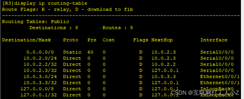
3、查看路由器路由表
R1:

R2:

R3:
R4:

三、实验结果
PC1地址:

PC2地址:

PC3地址:

PC1 ping PC2、PC3


 804
804


 被折叠的 条评论
为什么被折叠?
被折叠的 条评论
为什么被折叠?
 到【灌水乐园】发言


