


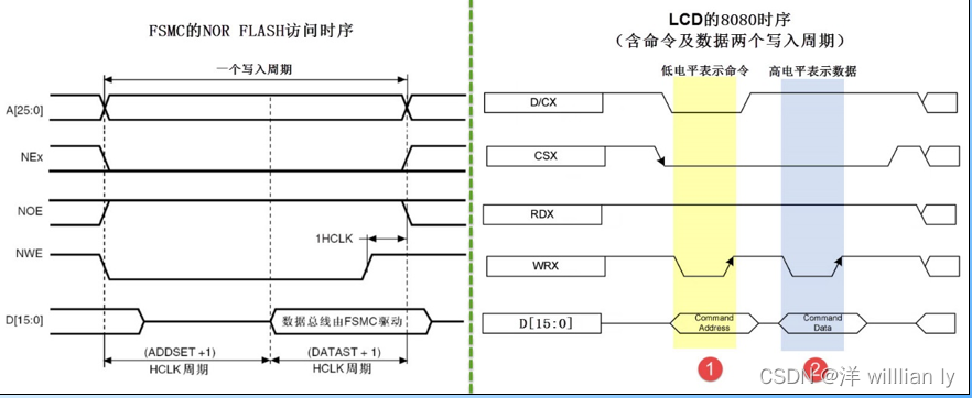
2,FSMC控制时序(模式B)和液晶控制器的时序对比
时序相同,那么主要是地址线和CSX信号线的差异
3,解决 CSX使能线问题
1-FSMC的地址信号线A[25:0]与8080的数据/命令选择线D/CX有区别。而对于D/CX线,它为高电平的时候表示数值,为低电平的时候表示命令,如果能使用FSMC的A地址线根据不同的情况产生对应的电平,那么就完全可以使用FSMC来产生8080接口需要的时序了
2-可以把FSMC的A0地址线(也可以使用其它A1/A2等地址线)与ILI9341芯片8080接口的D/CX信号线连接,那么当A0为高电平时(即D/CX为高电平),数据线D[15:0]的信号会被ILI9341理解为数值,若A0为低电平时(即D/CX为低电平),传输的信号则会被理解为命令
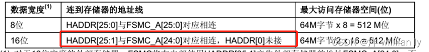
3-实际由于16位地址传递的问题,由于地址转化的关系HADDR转化到实际FSMC地址传递,会有所差异(ps:这一块在控制SRAM时刻,不会产生影响。但是通过单独引脚控制时刻,就会产生地址位的偏移)
会产生一个数据位的偏移,所以如果是控制数据位0,则实际在地址上要控制bit1;
例如DCX接线A23引脚,则需要控制bit24来实现转化;
4,存储器类型和对应FSMC地址数据段
1-存储器类型:NORFLASH
2-地址空间
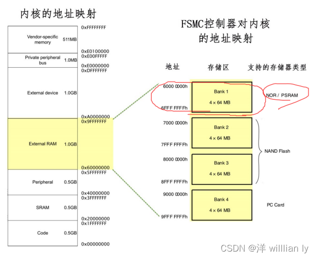
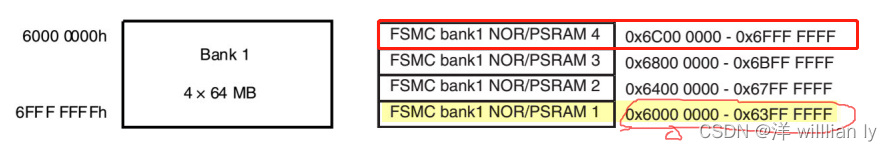
3- 对应A23调整,csx地址线,即对应bit24
#define LCD_sendDATA                    0x6D000000
#define LCD_sendCMD                     0x6C000000
5-FSMC初始化结构体
关于FSMC只介绍关键参数:
①FSMC结构初始化主要分为两个模块,时序初始化、整体FSMC初始化
1- FSMC结构初始化主要分为两个模块,时序初始化、整体FSMC初始化

配置好时序结构体后,再在整体初始化结构体中,进行地址传递,一起进行初始化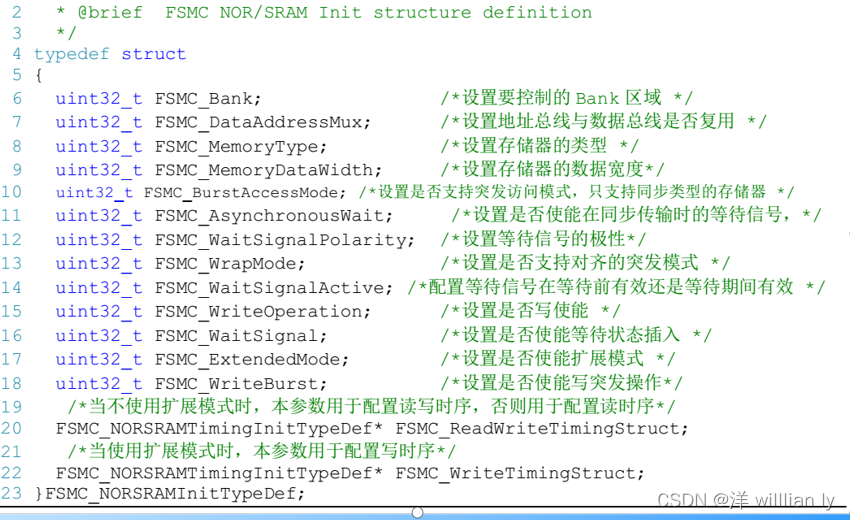
以上,fsmc对应LCD显示屏控制的核心逻辑已经介绍完毕,下面进入代码模块
三、代码模块
1,整体逻辑
①初始化对应GPIO端口
②初始化FSMC
③初始化LCD模块
④初始化发送数据、发送指令、接受数据模块
⑤显示窗口开辟
⑥RGB888数据转化RGB565函数建立
⑦矩形图形显示
ps:能够显示一个矩形,基本等于可以进行LCD驱动了,至于显示斜直线、圆等图形全部都是数学关系的转化;
2,正式进入代码模块
①初始化对应GPIO端口
FSMC模块引脚全部设置为复用推挽输出;
背光模块和复位不属于FSMC,属于GPIO模块,直接推挽输出;
void lcd_gpio_config(void)
{
	//开启GPIO时钟
	RCC_APB2PeriphClockCmd(RCC_APB2Periph_GPIOD
	                      |RCC_APB2Periph_GPIOE|RCC_APB2Periph_GPIOG,ENABLE);

	//配置GPIO
	//先配置FSMC数据信号线 D0-D15 ,复用推挽
	GPIO_InitTypeDef GPIO_InitStruct;
	GPIO_InitStruct.GPIO_Speed=GPIO_Speed_50MHz;
	GPIO_InitStruct.GPIO_Mode=GPIO_Mode_AF_PP;

	GPIO_InitStruct.GPIO_Pin=GPIO_Pin_14;
	GPIO_Init( GPIOD, &GPIO_InitStruct);//D0

	GPIO_InitStruct.GPIO_Pin=GPIO_Pin_15;
	GPIO_Init( GPIOD, &GPIO_InitStruct);//D1

	GPIO_InitStruct.GPIO_Pin=GPIO_Pin_0;
	GPIO_Init( GPIOD, &GPIO_InitStruct);//D2

	GPIO_InitStruct.GPIO_Pin=GPIO_Pin_1;
	GPIO_Init( GPIOD, &GPIO_InitStruct);//D3

	GPIO_InitStruct.GPIO_Pin=GPIO_Pin_7;
	GPIO_Init( GPIOE, &GPIO_InitStruct);//D4

	GPIO_InitStruct.GPIO_Pin=GPIO_Pin_8;
	GPIO_Init( GPIOE, &GPIO_InitStruct);//D5

	GPIO_InitStruct.GPIO_Pin=GPIO_Pin_9;
	GPIO_Init( GPIOE, &GPIO_InitStruct);//D6

	GPIO_InitStruct.GPIO_Pin=GPIO_Pin_10;
	GPIO_Init( GPIOE, &GPIO_InitStruct);//D7

	GPIO_InitStruct.GPIO_Pin=GPIO_Pin_11;
	GPIO_Init( GPIOE, &GPIO_InitStruct);//D8

	GPIO_InitStruct.GPIO_Pin=GPIO_Pin_12;
	GPIO_Init( GPIOE, &GPIO_InitStruct);//D9

	GPIO_InitStruct.GPIO_Pin=GPIO_Pin_13;
	GPIO_Init( GPIOE, &GPIO_InitStruct);//D10

	GPIO_InitStruct.GPIO_Pin=GPIO_Pin_14;
	GPIO_Init( GPIOE, &GPIO_InitStruct);//D11

	GPIO_InitStruct.GPIO_Pin=GPIO_Pin_15;
	GPIO_Init( GPIOE, &GPIO_InitStruct);//D12

	GPIO_InitStruct.GPIO_Pin=GPIO_Pin_8;
	GPIO_Init( GPIOD, &GPIO_InitStruct);//D13

	GPIO_InitStruct.GPIO_Pin=GPIO_Pin_9;
	GPIO_Init( GPIOD, &GPIO_InitStruct);//D14

	GPIO_InitStruct.GPIO_Pin=GPIO_Pin_10;
	GPIO_Init( GPIOD, &GPIO_InitStruct);//D15


	//配置相应FSMC控制引脚,复用推挽模式
//	 * FSMC_NOE   :LCD-RD
//	 * FSMC_NWE   :LCD-WR
//	 * FSMC_NE1   :LCD-CS
//	 * FSMC_A16  	:LCD-DC 地址线*****

    GPIO_InitStruct.GPIO_Pin=GPIO_Pin_2;
	GPIO_Init( GPIOE, &GPIO_InitStruct);// 地址线 A16   重要!

	GPIO_InitStruct.GPIO_Pin=GPIO_Pin_12;
	GPIO_Init( GPIOG, &GPIO_InitStruct);// cs片选

	GPIO_InitStruct.GPIO_Pin=GPIO_Pin_5;
	GPIO_Init( GPIOD, &GPIO_InitStruct);// WR  写使能

	GPIO_InitStruct.GPIO_Pin=GPIO_Pin_4;
	GPIO_Init( GPIOD, &GPIO_InitStruct);// RD  读


	//单独配置 RST BK引脚,推挽模式


	GPIO_InitStruct.GPIO_Mode=GPIO_Mode_Out_PP;
	GPIO_InitStruct.GPIO_Pin=GPIO_Pin_11;
	GPIO_Init( GPIOG, &GPIO_InitStruct);//复位引脚


	GPIO_InitStruct.GPIO_Mode=GPIO_Mode_Out_PP;
	GPIO_InitStruct.GPIO_Pin=GPIO_Pin_6;
	GPIO_Init( GPIOG, &GPIO_InitStruct);//背光引脚

}
②初始化FSMC
关键点:1-两个结构体;2-FSMC模式B;
3-地址区域bank1-sram4;
4-地址建立周期、数据建立周期
5-16位数据传递
6-非拓展模式
void LCD_FSMC_config(void)
{
	//定义两个结构体,一个是时序结构体、一个是整体fsmc模块结构体

	//先开启时钟
	RCC_AHBPeriphClockCmd(RCC_AHBPeriph_FSMC,ENABLE);//开启fsmc时钟

	//先配置读写时序结构体
	FSMC_NORSRAMTimingInitTypeDef readWriteTiming;
	readWriteTiming.FSMC_AccessMode=FSMC_AccessMode_B;//控制sram选择模式B
	readWriteTiming.FSMC_AddressHoldTime=0x00;//地址保持时间0
	//地址建立时间(ADDSET)为1个HCLK 1/72M=14ns,addset+1
	readWriteTiming.FSMC_AddressSetupTime=0x01;


	readWriteTiming.FSMC_BusTurnAroundDuration=0;
	readWriteTiming.FSMC_CLKDivision=0;
	readWriteTiming.FSMC_DataLatency=0x00;  //这三个,模式B未用到


	//数据保持时间(DATAST)+ 1个HCLK = 3/72M=42ns(对EM的SRAM芯片)
	readWriteTiming.FSMC_DataSetupTime=0x04;


	//下面进行FSMC-SRAM初始化
	FSMC_NORSRAMInitTypeDef FSMC_NORSRAMInitStruct;

	//SRAM的地址区域在bank1-SRAM3
	FSMC_NORSRAMInitStruct.FSMC_Bank= FSMC_Bank1_NORSRAM4 ;
	//异步,不适用突发模式
	FSMC_NORSRAMInitStruct.FSMC_BurstAccessMode=FSMC_BurstAccessMode_Disable ;
	//等待时间
	FSMC_NORSRAMInitStruct.FSMC_AsynchronousWait=FSMC_AsynchronousWait_Disable ;
	//数据总线和地址总线不复用
	FSMC_NORSRAMInitStruct.FSMC_DataAddressMux=FSMC_DataAddressMux_Disable ;
	//扩展模式不开启,读写时序保持一种
	FSMC_NORSRAMInitStruct.FSMC_ExtendedMode=FSMC_ExtendedMode_Disable ;
	//数据宽度16位
	FSMC_NORSRAMInitStruct.FSMC_MemoryDataWidth=FSMC_MemoryDataWidth_16b ;
	//存储器类型  SRAM
	FSMC_NORSRAMInitStruct.FSMC_MemoryType=FSMC_MemoryType_NOR  ;

	FSMC_NORSRAMInitStruct.FSMC_WaitSignal=FSMC_WaitSignal_Disable ;
	FSMC_NORSRAMInitStruct.FSMC_WaitSignalActive=FSMC_WaitSignalActive_BeforeWaitState ;
	FSMC_NORSRAMInitStruct.FSMC_WaitSignalPolarity=FSMC_WaitSignalPolarity_Low ;
	FSMC_NORSRAMInitStruct.FSMC_WrapMode=FSMC_WrapMode_Disable;
	FSMC_NORSRAMInitStruct.FSMC_WriteBurst=FSMC_WriteBurst_Disable  ;

	//写使能
	FSMC_NORSRAMInitStruct.FSMC_WriteOperation=FSMC_WriteOperation_Enable ;
	FSMC_NORSRAMInitStruct.FSMC_ReadWriteTimingStruct=&readWriteTiming;
	//扩展模式有效
	FSMC_NORSRAMInitStruct.FSMC_WriteTimingStruct=&readWriteTiming;

   FSMC_NORSRAMInit(&FSMC_NORSRAMInitStruct);
   //启动
   FSMC_NORSRAMCmd( FSMC_Bank1_NORSRAM4,ENABLE);

}
③初始化LCD模块1
void LCDconfig(void)
{
	lcd_gpio_config();
	LCD_FSMC_config();

	//复位LCD
	GPIO_ResetBits(GPIOG,GPIO_Pin_11);//低使能复位
	LCD_Delay ( 0xAFF );
	GPIO_SetBits(GPIOG,GPIO_Pin_11);
	LCD_Delay ( 0xAFF );

	//开启背光,低电平点亮
	GPIO_ResetBits(GPIOG,GPIO_Pin_6);

}
④初始化LCD模块2
void LCD_init(void)
{
	    /*  Power control B (CFh)  */

    LCD_writecmd ( 0xCF  );
    LCD_writedata ( 0x00  );
    LCD_writedata ( 0xC1  );
    LCD_writedata ( 0x30  );

    /*  Power on sequence control (EDh) */

    LCD_writecmd ( 0xED );
    LCD_writedata ( 0x64 );
    LCD_writedata ( 0x03 );
    LCD_writedata ( 0x12 );
    LCD_writedata ( 0x81 );

    /*  Driver timing control A (E8h) */

    LCD_writecmd ( 0xE8 );
    LCD_writedata ( 0x85 );
    LCD_writedata ( 0x10 );
    LCD_writedata ( 0x78 );

    /*  Power control A (CBh) */

    LCD_writecmd ( 0xCB );
    LCD_writedata ( 0x39 );
    LCD_writedata ( 0x2C );
    LCD_writedata ( 0x00 );
    LCD_writedata ( 0x34 );
    LCD_writedata ( 0x02 );

    /* Pump ratio control (F7h) */

    LCD_writecmd ( 0xF7 );
    LCD_writedata ( 0x20 );

    /* Driver timing control B */

    LCD_writecmd ( 0xEA );
    LCD_writedata ( 0x00 );
    LCD_writedata ( 0x00 );


    /* Power Control 1 (C0h) */

    LCD_writecmd ( 0xC0 );   //Power control
    LCD_writedata ( 0x21 );  //VRH[5:0]

    /* Power Control 2 (C1h) */

    LCD_writecmd ( 0xC1 );   //Power control
    LCD_writedata ( 0x11 );  //SAP[2:0];BT[3:0]

    /* VCOM Control 1 (C5h) */
    LCD_writecmd ( 0xC5 );
    LCD_writedata ( 0x2D );
    LCD_writedata ( 0x33 );

    /*  VCOM Control 2 (C7h)  */
//	LCD_writecmd ( 0xC7 );
//	LCD_writedata ( 0XC0 );

    /* memory access control set */

    LCD_writecmd ( 0x36 );   //Memory Access Control
    LCD_writedata ( 0x00 );  /*竖屏  左上角到 (起点)到右下角 (终点)扫描方式*/


    LCD_writecmd(0x3A);
    LCD_writedata(0x55);

      /* Frame Rate Control (In Normal Mode/Full Colors) (B1h) */

    LCD_writecmd ( 0xB1 );
    LCD_writedata ( 0x00 );
    LCD_writedata ( 0x17 );

    /*  Display Function Control (B6h) */

    LCD_writecmd ( 0xB6 );
    LCD_writedata ( 0x0A );
    LCD_writedata ( 0xA2 );

    LCD_writecmd(0xF6);
    LCD_writedata(0x01);
    LCD_writedata(0x30);

    /* Enable 3G (F2h) */
    LCD_writecmd ( 0xF2 );
    LCD_writedata ( 0x00 );

    /* Gamma Set (26h) */
    LCD_writecmd ( 0x26 );
    LCD_writedata ( 0x01 );


    /* Positive Gamma Correction */
    LCD_writecmd(0xe0); //Positive gamma
    LCD_writedata(0xd0);
    LCD_writedata(0x00);
    LCD_writedata(0x02);
    LCD_writedata(0x07);
    LCD_writedata(0x0b);
    LCD_writedata(0x1a);
    LCD_writedata(0x31);
    LCD_writedata(0x54);
    LCD_writedata(0x40);
    LCD_writedata(0x29);
    LCD_writedata(0x12);
    LCD_writedata(0x12);
    LCD_writedata(0x12);
    LCD_writedata(0x17);

    /* Negative Gamma Correction (E1h) */
    LCD_writecmd(0xe1); //Negative gamma
    LCD_writedata(0xd0);
    LCD_writedata(0x00);
    LCD_writedata(0x02);
    LCD_writedata(0x07);
    LCD_writedata(0x05);
    LCD_writedata(0x25);
    LCD_writedata(0x2d);
    LCD_writedata(0x44);
    LCD_writedata(0x45);
    LCD_writedata(0x1c);
    LCD_writedata(0x18);
    LCD_writedata(0x16);
    LCD_writedata(0x1c);
    LCD_writedata(0x1d);


//	/* column address control set */
//	LCD_writecmd ( CMD_SetCoordinateX );
//	LCD_writedata ( 0x00 );
//	LCD_writedata ( 0x00 );
//	LCD_writedata ( 0x00 );
//	LCD_writedata ( 0xEF );
//
//	/* page address control set */
//
//	LCD_writecmd ( CMD_SetCoordinateY );
//	LCD_writedata ( 0x00 );
//	LCD_writedata ( 0x00 );
//	LCD_writedata ( 0x01 );
//	LCD_writedata ( 0x3F );


    /* Sleep Out (11h)  */
    LCD_writecmd ( 0x11 );	  //Exit Sleep
    LCD_Delay ( 0xAFFf<<2 );


    /* Display ON (29h) */
    LCD_writecmd ( 0x29 );   //Display on

    LCD_writecmd(0x2c);
}
⑤初始化发送数据、发送指令、接受数据模块
注意,对应地址要声明为volatile类型,避免编译器优化,每次都从内存中检查数据,而不是从内核寄存器直接读取;
不然读数据时刻会出错
//写数据
void LCD_writedata(uint16_t DATA)
{
*(__IO uint16_t*) LCD_sendDATA = DATA;
}
//写指令
void LCD_writecmd(uint16_t usDATA)
{
*(__IO uint16_t*) LCD_sendCMD = usDATA;
}
**自我介绍一下,小编13年上海交大毕业,曾经在小公司待过,也去过华为、OPPO等大厂,18年进入阿里一直到现在。**
**深知大多数嵌入式工程师,想要提升技能,往往是自己摸索成长或者是报班学习,但对于培训机构动则几千的学费,着实压力不小。自己不成体系的自学效果低效又漫长,而且极易碰到天花板技术停滞不前!**
**因此收集整理了一份《2024年嵌入式&物联网开发全套学习资料》,初衷也很简单,就是希望能够帮助到想自学提升又不知道该从何学起的朋友,同时减轻大家的负担。**


**既有适合小白学习的零基础资料,也有适合3年以上经验的小伙伴深入学习提升的进阶课程,基本涵盖了95%以上嵌入式&物联网开发知识点,真正体系化!**


**由于文件比较大,这里只是将部分目录大纲截图出来,每个节点里面都包含大厂面经、学习笔记、源码讲义、实战项目、讲解视频,并且后续会持续更新**
**如果你觉得这些内容对你有帮助,可以+V:Vip1104z获取!!! (备注:嵌入式)**
<img src="https://img-community.csdnimg.cn/images/73bb5de17851459088c6af944156ee24.jpg" alt="img" style="zoom: 67%;" />
# 最后
**资料整理不易,觉得有帮助的朋友可以帮忙点赞分享支持一下小编~**
**你的支持,我的动力;祝各位前程似锦,offer不断,步步高升!!!**
[外链图片转存中...(img-iQ8vyEQh-1712311183053)]
**既有适合小白学习的零基础资料,也有适合3年以上经验的小伙伴深入学习提升的进阶课程,基本涵盖了95%以上嵌入式&物联网开发知识点,真正体系化!**
[外链图片转存中...(img-nKryOnsD-1712311183054)]
[外链图片转存中...(img-n77KoudR-1712311183055)]
**由于文件比较大,这里只是将部分目录大纲截图出来,每个节点里面都包含大厂面经、学习笔记、源码讲义、实战项目、讲解视频,并且后续会持续更新**
**如果你觉得这些内容对你有帮助,可以+V:Vip1104z获取!!! (备注:嵌入式)**
<img src="https://img-community.csdnimg.cn/images/73bb5de17851459088c6af944156ee24.jpg" alt="img" style="zoom: 67%;" />
# 最后
**资料整理不易,觉得有帮助的朋友可以帮忙点赞分享支持一下小编~**
**你的支持,我的动力;祝各位前程似锦,offer不断,步步高升!!!**
**[更多资料点击此处获qu!!](https://bbs.csdn.net/topics/618376385)**


 1万+
1万+


 被折叠的 条评论
为什么被折叠?
被折叠的 条评论
为什么被折叠?
 到【灌水乐园】发言


