


1.实验拓扑:
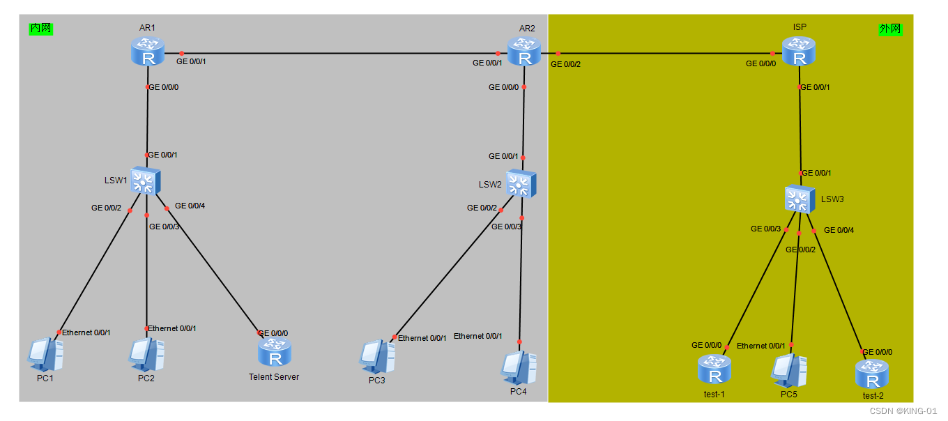
2.实验要求(问题):
1.ISP路由器仅配置IP地址;
2.内网基于192.168.1.0/24网段进行IP划分;
3.R1/R2之间使用OSPF做到内网全通,单区域;
4.PC1-PC4使用DHCP服务获取地址;
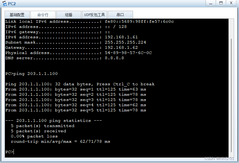
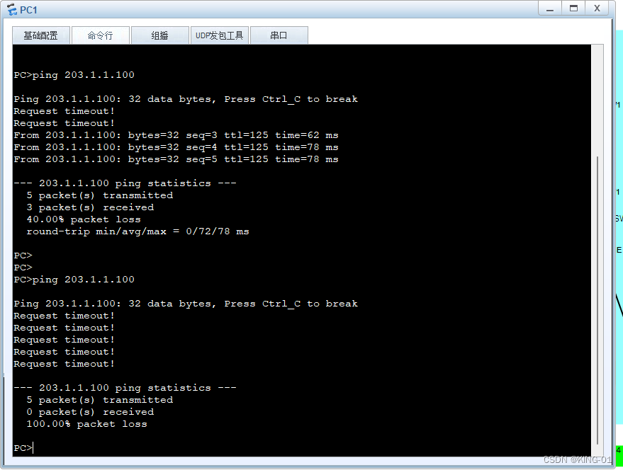
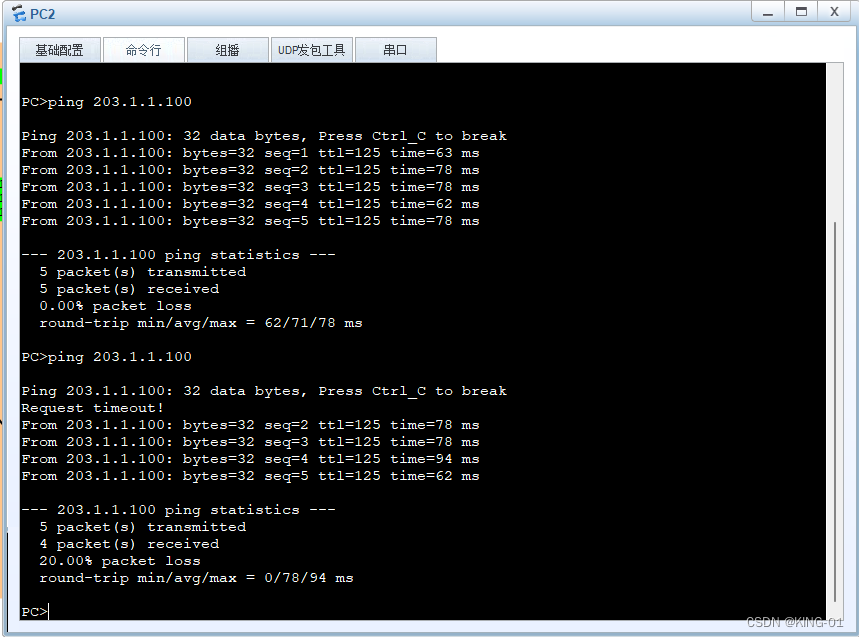
5.PC2-PC4可以访问PC5,PC1不行;
6.R2出口只拥有一个公网IP;
7.test-1设备可以登陆内网telent服务器,但test-2不可。
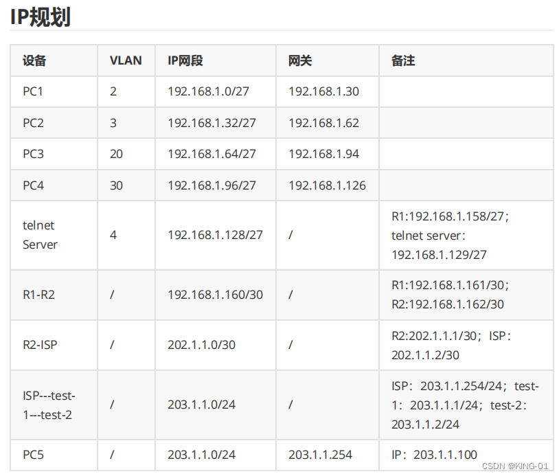
3.附件资料:
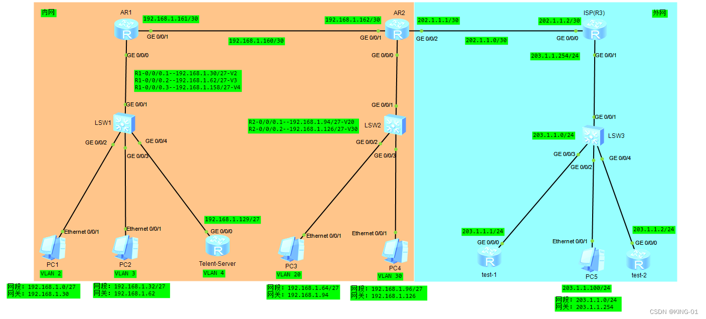
4.结合附件对拓扑进行标注:
5.实验要求(分析):
1、ISP路由器仅配置IP地址;
2、test-1和test-2仅作为代替终端设备进行测试使用,路由采用静态路由;
3、R1/R2之间使用OSPF做到内网全通,单区域,OSPF使用一条命令进行宣告(直接宣告192.168.1.0网段);router-ID分别为1.1.1.1和2.2.2.2;OSPF进程为1;
4、PC1-PC4使用DHCP获取地址,地址池名称使用1,2;
5、PC1不能访问PC5,ac1编号为3000;
6、R2出口只拥有一个公网IP;
7、test-1设备可以登录内网telnet服务器,test-2不行;ac1编号为3000;
8、telnet服务器的账号密码为huawei/123456;
9、内网用户可以正常访问ISP(边界做默认路由);
10、公网设备的路中表不能有私网的路中,使用nat(arl编号为2000);
11、内网设备的路由表不能有公网的路由,边界下发默认路由;
12、VLAN及IP规划查看附件材料(所有trunk链路按照最少VLAN透传原则放通)。
6.实验思路:
首先我将对应上面的要求一条一条阐述实现原理:
1、ISP路由器仅配置IP地址;
这里我们主要配置IP,然后让ISP与R2之间用缺省路由指向ISP便好。
2、test-1和test-2仅作为代替终端设备进行测试使用,路由采用静态路由;
3、R1/R2之间使用OSPF做到内网全通,单区域,OSPF使用一条命令进行宣告(直接宣告192.168.1.0网段);router-ID分别为1.1.1.1和2.2.2.2;OSPF进程为1;
4、PC1-PC4使用DHCP获取地址,地址池名称使用1,2;
5、PC1不能访问PC5,ac1编号为3000;
6、R2出口只拥有一个公网IP;
这里表示之后的nat配置使用easy nat以及端口映射。
7、test-1设备可以登录内网telnet服务器,test-2不行;ac1编号为3000;
8、telnet服务器的账号密码为huawei/123456;
9、内网用户可以正常访问ISP(边界做默认路由);
10、公网设备的路中表不能有私网的路中,使用nat(arl编号为2000);
11、内网设备的路由表不能有公网的路由,边界下发默认路由;
12、VLAN及IP规划查看附件材料(所有trunk链路按照最少VLAN透传原则放通)。
7.实验步骤:
(1)给两个交换机分别配置VLAN并配置永不超时
RW1:
The device is running!

<Huawei>sys
Enter system view, return user view with Ctrl+Z.
[Huawei]sys RW1
[RW1]user-interface console 0
[RW1-ui-console0]idle-timeout 0 0
[RW1-ui-console0]quit
[RW1]vlan batch 2 3 4
[RW1]int g0/0/2
[RW1-GigabitEthernet0/0/2]port link-type access
[RW1-GigabitEthernet0/0/2]port default vlan 2
[RW1-GigabitEthernet0/0/2]int g0/0/3
[RW1-GigabitEthernet0/0/3]port link-type access
[RW1-GigabitEthernet0/0/3]port default vlan 3
[RW1-GigabitEthernet0/0/3]int g0/0/4
[RW1-GigabitEthernet0/0/4]port link-type access
[RW1-GigabitEthernet0/0/4]port default vlan 4
[RW1-GigabitEthernet0/0/4]int g0/0/1
[RW1-GigabitEthernet0/0/1]port link-type trunk
[RW1-GigabitEthernet0/0/1]port trunk allow-pass vlan 2 3 4
[RW1-GigabitEthernet0/0/1]quit
RW2:
The device is running!
<Huawei>sys
Enter system view, return user view with Ctrl+Z.
[Huawei]sys RW2
[RW2]user-interface console 0
[RW2-ui-console0]idle-timeout 0 0
[RW2-ui-console0]quit
[RW2]vlan batch 20 30
[RW2]int g0/0/2
[RW2-GigabitEthernet0/0/2]port link-type access
[RW2-GigabitEthernet0/0/2]port default vlan 20
[RW2-GigabitEthernet0/0/2]int g0/0/3
[RW2-GigabitEthernet0/0/3]port link-type access
[RW2-GigabitEthernet0/0/3]port default vlan 3
[RW2-GigabitEthernet0/0/3]int g0/0/1
[RW2-GigabitEthernet0/0/1]port link-type trunk
[RW2-GigabitEthernet0/0/1]port trunk allow-pass vlan
[RW2-GigabitEthernet0/0/1]port trunk allow-pass vlan 20 30
[RW2-GigabitEthernet0/0/1]quit
查看VLAN:
[RW1]display vlan
The total number of vlans is : 4
--------------------------------------------------------------------------------
U: Up;         D: Down;         TG: Tagged;         UT: Untagged;
MP: Vlan-mapping;               ST: Vlan-stacking;
#: ProtocolTransparent-vlan;    *: Management-vlan;
--------------------------------------------------------------------------------

VID  Type    Ports
--------------------------------------------------------------------------------
1    common  UT:GE0/0/1(U)      GE0/0/5(D)      GE0/0/6(D)      GE0/0/7(D)
                GE0/0/8(D)      GE0/0/9(D)      GE0/0/10(D)     GE0/0/11(D)
                GE0/0/12(D)     GE0/0/13(D)     GE0/0/14(D)     GE0/0/15(D)
                GE0/0/16(D)     GE0/0/17(D)     GE0/0/18(D)     GE0/0/19(D)
                GE0/0/20(D)     GE0/0/21(D)     GE0/0/22(D)     GE0/0/23(D)
                GE0/0/24(D)

2    common  UT:GE0/0/2(U)

             TG:GE0/0/1(U)

3    common  UT:GE0/0/3(U)

             TG:GE0/0/1(U)

4    common  UT:GE0/0/4(U)

             TG:GE0/0/1(U)


VID  Status  Property      MAC-LRN Statistics Description
--------------------------------------------------------------------------------

1    enable  default       enable  disable    VLAN 0001
2    enable  default       enable  disable    VLAN 0002
3    enable  default       enable  disable    VLAN 0003
4    enable  default       enable  disable    VLAN 0004
[RW1]
[RW2]display vlan
The total number of vlans is : 3
--------------------------------------------------------------------------------
U: Up;         D: Down;         TG: Tagged;         UT: Untagged;
MP: Vlan-mapping;               ST: Vlan-stacking;
#: ProtocolTransparent-vlan;    *: Management-vlan;
--------------------------------------------------------------------------------

VID  Type    Ports
--------------------------------------------------------------------------------
1    common  UT:GE0/0/1(U)      GE0/0/4(D)      GE0/0/5(D)      GE0/0/6(D)
                GE0/0/7(D)      GE0/0/8(D)      GE0/0/9(D)      GE0/0/10(D)
                GE0/0/11(D)     GE0/0/12(D)     GE0/0/13(D)     GE0/0/14(D)
                GE0/0/15(D)     GE0/0/16(D)     GE0/0/17(D)     GE0/0/18(D)
                GE0/0/19(D)     GE0/0/20(D)     GE0/0/21(D)     GE0/0/22(D)
                GE0/0/23(D)     GE0/0/24(D)

20   common  UT:GE0/0/2(U)
             TG:GE0/0/1(U)

30   common  UT:GE0/0/3(U)

             TG:GE0/0/1(U)


VID  Status  Property      MAC-LRN Statistics Description
--------------------------------------------------------------------------------

1    enable  default       enable  disable    VLAN 0001
20   enable  default       enable  disable    VLAN 0020
30   enable  default       enable  disable    VLAN 0030
[RW2]
(2)进行虚拟子接口封装下放网关及进行DHCP服务
R1路由器:
The device is running!

<Huawei>sys
Enter system view, return user view with Ctrl+Z.
[Huawei]sysname r1
[r1]user-interface console 0
[r1-ui-console0]i
[r1-ui-console0]idle-timeout 0 0
[r1-ui-console0]int g0/0/0.1
[r1-GigabitEthernet0/0/0.1]dot1q  termination vid 2
[r1-GigabitEthernet0/0/0.1]ip address 192.168.1.30 27
[r1-GigabitEthernet0/0/0.1]int g0/0/0.2
[r1-GigabitEthernet0/0/0.2]dot1q termination vid 3
[r1-GigabitEthernet0/0/0.2]ip address 192.168.1.62 27
[r1-GigabitEthernet0/0/0.2]int g0/0/0.3
[r1-GigabitEthernet0/0/0.3]dot1q termination vid 4
[r1-GigabitEthernet0/0/0.3]ip address 192.168.1.158 27
[r1-GigabitEthernet0/0/0.3]quit
[r1]dhcp enable
[r1]ip pool 1
[r1-ip-pool-1]network 192.168.1.0 mask 27
[r1-ip-pool-1]gateway-list 192.168.1.30
[r1-ip-pool-1]dns-list 8.8.8.8
[r1-ip-pool-1]quit
[r1]ip pool 2
[r1-ip-pool-2]network 192.168.1.32 mask 27
[r1-ip-pool-2]gateway-list 192.168.1.62
[r1-ip-pool-2]dns-list 8.8.8.8
[r1-ip-pool-2]quit
[r1]int g0/0/0.1
[r1-GigabitEthernet0/0/0.1]dhcp select global
[r1-GigabitEthernet0/0/0.1]arp broadcast enable
[r1-GigabitEthernet0/0/0.1]int g0/0/0.2
[r1-GigabitEthernet0/0/0.2]dhcp select global
[r1-GigabitEthernet0/0/0.2]arp broadcast enable
[r1-GigabitEthernet0/0/0.2]int g0/0/0.3
[r1-GigabitEthernet0/0/0.3]dhcp select global
[r1-GigabitEthernet0/0/0.3]arp broadcast enable
[r1-GigabitEthernet0/0/0.3]quit
[r1]
R2路由器:
The device is running!
<Huawei>sys
Enter system view, return user view with Ctrl+Z.
[Huawei]sys R2
[R2]user-interface console 0
[R2-ui-console0]idle-timeout 0 0
[R2-ui-console0]int g0/0/0.1
[R2-GigabitEthernet0/0/0.1]dot1q termination vid 20
[R2-GigabitEthernet0/0/0.1]ip address 192.168.1.94 27
[R2-GigabitEthernet0/0/0.1]int g0/0/0.2
[R2-GigabitEthernet0/0/0.2]dot1q termination vid 30
[R2-GigabitEthernet0/0/0.2]ip address 192.168.1.126 27
[R2-GigabitEthernet0/0/0.2]quit
[R2]dhcp enable
[R2]ip pool 1
[R2-ip-pool-1]network 192.168.1.64 mask 27
[R2-ip-pool-1]gateway-list 192.168.1.94
[R2-ip-pool-1]dns-list 8.8.8.8
[R2-ip-pool-1]quit
[R2]ip pool 2
[R2-ip-pool-2]network 192.168.1.96 mask 27
[R2-ip-pool-2]gateway-list 192.168.1.126
[R2-ip-pool-2]dns-list 8.8.8.8
[R2-ip-pool-2]quit
[R2]int g0/0/0.1
[R2-GigabitEthernet0/0/0.1]dhcp select global
[R2-GigabitEthernet0/0/0.1]arp broadcast enable
[R2-GigabitEthernet0/0/0.1]int g0/0/0.2
[R2-GigabitEthernet0/0/0.2]dhcp select global
[R2-GigabitEthernet0/0/0.2]arp broadcast enable
[R2-GigabitEthernet0/0/0.2]quit
[R2]
(3)配置路由器的接口IP地址以及剩下几个路由器的命名,接口配置
R1实现代码:
[r1]int g0/0/1
[r1-GigabitEthernet0/0/1]ip address 192.168.1.161 30
[r1-GigabitEthernet0/0/1]quit
[r1]
R2实验代码:
[R2]int g0/0/1
[R2-GigabitEthernet0/0/1]ip address 192.168.1.162 30
[R2-GigabitEthernet0/0/1]int g0/0/2
[R2-GigabitEthernet0/0/2]ip address 202.1.1.1 30
[R2-GigabitEthernet0/0/2]quit
[R2]
test-1实现代码:
The device is running!

<Huawei>sys
Enter system view, return user view with Ctrl+Z.
[Huawei]sys test-1
[test-1]user-interface console 0
[test-1-ui-console0]idle-timeout 0 0
[test-1-ui-console0]quit
[test-1]int g0/0/0
[test-1-GigabitEthernet0/0/0]ip address 203.1.1.1 24
[test-1-GigabitEthernet0/0/0]quit
[test-1]
test-2实现代码:
The device is running!

<Huawei>sys
Enter system view, return user view with Ctrl+Z.
[Huawei]sysname test-2
[test-2]user-interface console 0
[test-2-ui-console0]i
[test-2-ui-console0]idle-timeout 0 0
[test-2-ui-console0]quit
[test-2]int g0/0/0
[test-2-GigabitEthernet0/0/0]ip address 203.1.1.2 24
[test-2-GigabitEthernet0/0/0]quit
[test-2]
Telent-Server实现代码:
The device is running!

<Huawei>sys
Enter system view, return user view with Ctrl+Z.
[Huawei]sys Telnet Server
[Telnet Server]user-interface console 0
[Telnet Server-ui-console0]idle-timeout 0 0
[Telnet Server-ui-console0]quit
[Telnet Server]int g0/0/0
[Telnet Server-GigabitEthernet0/0/0]ip address 192.168.1.129 27
[Telnet Server-GigabitEthernet0/0/0]quit
[Telnet Server]
ISP(R3)实现代码:
The device is running!

<Huawei>sys
Enter system view, return user view with Ctrl+Z.
[Huawei]sys ISP
[ISP]user-interface console 0
[ISP-ui-console0]idle-timeout 0 0
[ISP-ui-console0]quit
[ISP]int g0/0/0
[ISP-GigabitEthernet0/0/0]ip address 202.1.1.2 30
[ISP-GigabitEthernet0/0/0]int g0/0/1
[ISP-GigabitEthernet0/0/1]ip address 203.1.1.254 24
[ISP-GigabitEthernet0/0/1]quit
[ISP]
(4)配置ospf实现R1与R2之间的通信
R1配置代码:
[r1]ospf 1 router-id 1.1.1.1
[r1-ospf-1]area 0
[r1-ospf-1-area-0.0.0.0]network 192.168.1.0 0.0.0.255
[r1-ospf-1-area-0.0.0.0]quit
[r1-ospf-1]quit
[r1]
R2配置代码:
[R2]ospf 1 router-id 2.2.2.2
[R2-ospf-1]area 0
[R2-ospf-1-area-0.0.0.0]network 192.168.1.0 0.0.0.255
[R2-ospf-1-area-0.0.0.0]quit
[R2-ospf-1]quit
[R2]
(5)在Telnet服务器上配置缺省路由实现通信:
Telent-Sever实现代码:
[Telnet Server]ip route-static 0.0.0.0 0 192.168.1.158
[Telnet Server]
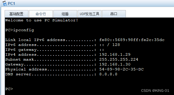
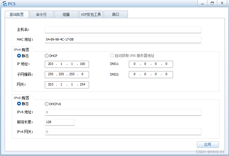
(6)PC端获取IP,并对PC5手动配置IP


(7)测试内网连通性
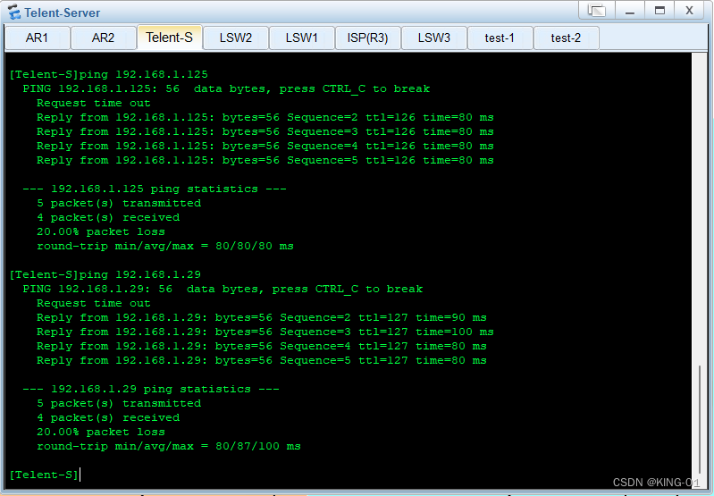
Telent-Server实现代码:
[Telnet Server]ping 192.168.1.158
  PING 192.168.1.158: 56  data bytes, press CTRL_C to break
    Reply from 192.168.1.158: bytes=56 Sequence=1 ttl=255 time=120 ms
    Reply from 192.168.1.158: bytes=56 Sequence=2 ttl=255 time=40 ms
    Reply from 192.168.1.158: bytes=56 Sequence=3 ttl=255 time=40 ms
    Reply from 192.168.1.158: bytes=56 Sequence=4 ttl=255 time=50 ms
    Reply from 192.168.1.158: bytes=56 Sequence=5 ttl=255 time=40 ms

  --- 192.168.1.158 ping statistics ---
    5 packet(s) transmitted
    5 packet(s) received
    0.00% packet loss
    round-trip min/avg/max = 40/58/120 ms

[Telnet Server]ping 192.168.1.125
  PING 192.168.1.125: 56  data bytes, press CTRL_C to break
    Request time out
    Reply from 192.168.1.125: bytes=56 Sequence=2 ttl=126 time=70 ms
    Reply from 192.168.1.125: bytes=56 Sequence=3 ttl=126 time=80 ms
    Reply from 192.168.1.125: bytes=56 Sequence=4 ttl=126 time=70 ms
    Reply from 192.168.1.125: bytes=56 Sequence=5 ttl=126 time=100 ms

  --- 192.168.1.125 ping statistics ---
    5 packet(s) transmitted
    4 packet(s) received
    20.00% packet loss
    round-trip min/avg/max = 70/80/100 ms

[Telnet Server]ping 192.168.1.29
  PING 192.168.1.29: 56  data bytes, press CTRL_C to break
    Request time out
    Reply from 192.168.1.29: bytes=56 Sequence=2 ttl=127 time=90 ms
    Reply from 192.168.1.29: bytes=56 Sequence=3 ttl=127 time=80 ms
    Reply from 192.168.1.29: bytes=56 Sequence=4 ttl=127 time=90 ms
    Reply from 192.168.1.29: bytes=56 Sequence=5 ttl=127 time=70 ms

  --- 192.168.1.29 ping statistics ---
    5 packet(s) transmitted
    4 packet(s) received
    20.00% packet loss
    round-trip min/avg/max = 70/82/90 ms

[Telnet Server]
(8)给R2配置缺省指向外网,并进行OSPF,配置NAT技术
这里配置acl抓取感兴趣流量,这里要求最简化(我没有划分到最简),也是建议,同时为了便于管理,在以后的网络项目经验中,也应该进行考虑网络的全面性以及可管理性
R2配置代码:
[R2]ip route-static 0.0.0.0 0 202.1.1.2
[R2]ospf 1 router-id 2.2.2.2
[R2-ospf-1]default-route-advertise
[R2-ospf-1]quit
[R2]acl 2000
[R2-acl-basic-2000]rule permit source 192.168.1.0 0.0.0.255
[R2-acl-basic-2000]quit
[R2]int g0/0/2
[R2-GigabitEthernet0/0/2]nat outbound 2000
[R2-GigabitEthernet0/0/2]quit
[R2]
(9)测试内网内与外网PC5连通性
展示如下:
(10)test-1和test-2配置静态路由
test-1:
[test-1]ip route-static 202.1.1.0 30 203.1.1.254
[test-1]
test-2:
[test-2]ip route-static 202.1.1.0 30 203.1.1.254
[test-2]
(11)查看ISP的路由表
ISP(R3)实现代码:
[ISP]display ip routing-table
Route Flags: R - relay, D - download to fib
------------------------------------------------------------------------------
Routing Tables: Public
         Destinations : 10       Routes : 10

Destination/Mask    Proto   Pre  Cost      Flags NextHop         Interface

      127.0.0.0/8   Direct  0    0           D   127.0.0.1       InLoopBack0
      127.0.0.1/32  Direct  0    0           D   127.0.0.1       InLoopBack0
127.255.255.255/32  Direct  0    0           D   127.0.0.1       InLoopBack0
      202.1.1.0/30  Direct  0    0           D   202.1.1.2       GigabitEthernet
0/0/0
      202.1.1.2/32  Direct  0    0           D   127.0.0.1       GigabitEthernet
0/0/0
      202.1.1.3/32  Direct  0    0           D   127.0.0.1       GigabitEthernet
0/0/0
      203.1.1.0/24  Direct  0    0           D   203.1.1.254     GigabitEthernet
0/0/1
    203.1.1.254/32  Direct  0    0           D   127.0.0.1       GigabitEthernet
0/0/1
    203.1.1.255/32  Direct  0    0           D   127.0.0.1       GigabitEthernet
0/0/1
255.255.255.255/32  Direct  0    0           D   127.0.0.1       InLoopBack0

[ISP]
(12)配置acl来不能让PC1访问PC5
R1的实现代码:
[r1]acl 3000
[r1-acl-adv-3000]rule deny icmp source 192.168.1.29 0 destination 203.1.1.100 0
[r1-acl-adv-3000]quit
[r1]int g0/0/0.1
[r1-GigabitEthernet0/0/0.1]traffic-filter inbound acl 3000
[r1-GigabitEthernet0/0/0.1]quit
[r1]
再次测试用PC1pingPC5以及PC2pingPC5:
(13)在telnet server路由器进行配置telnet
Telent-Server实现代码:
[Telnet Server]aaa
[Telnet Server-aaa]local-user huawei password cipher 123456 privilege level 15
[Telnet Server-aaa]local-user huawei service-type telnet
[Telnet Server-aaa]quit
[Telnet Server]user-interface vty 0 4
[Telnet Server-ui-vty0-4]authentication-mode aaa
[Telnet Server-ui-vty0-4]quit
[Telnet Server]
(14)配置端口映射
R2的配置代码:
[R2]int g0/0/2
[R2-GigabitEthernet0/0/2]nat server protocol tcp global current-interface 23 ins
ide 192.168.1.129 23
Are you sure to continue?[Y/N]:y
[R2-GigabitEthernet0/0/2]quit
[R2]
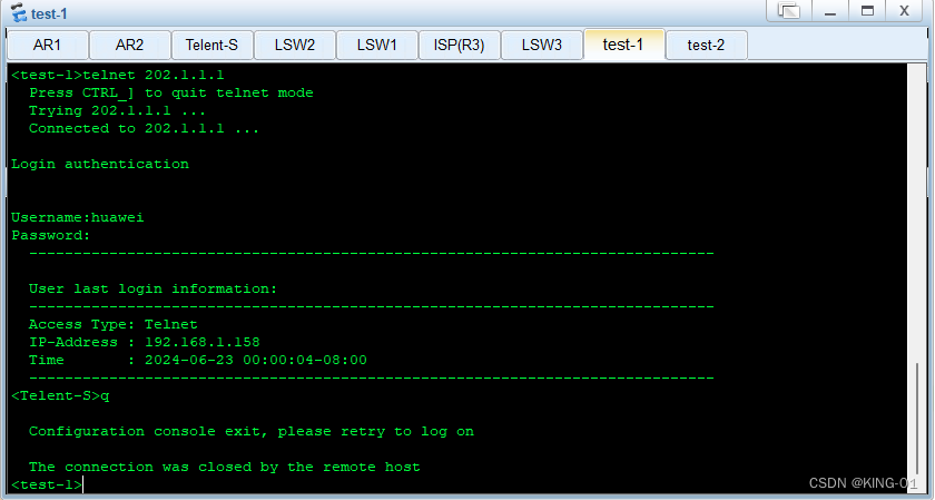
测试在test-1上进行远程登陆:
<test-1>telnet 202.1.1.1
  Press CTRL_] to quit telnet mode
  Trying 202.1.1.1 ...
  Connected to 202.1.1.1 ...

Login authentication


Username:huawei
Password:
  -----------------------------------------------------------------------------

  User last login information:
  -----------------------------------------------------------------------------
  Access Type: Telnet
  IP-Address : 192.168.1.162
  Time       : 2023-05-10 22:26:04-08:00
  -----------------------------------------------------------------------------
<Telnet Server>quit

  Configuration console exit, please retry to log on

  The connection was closed by the remote host
<test-1>
(15)配置ACL拒绝test-2的包
ISP(R3)配置代码:
[ISP]acl 3000
[ISP-acl-adv-3000]
[ISP-acl-adv-3000]rule deny tcp source 203.1.1.2 0 destination 202.1.1.1 0 desti
nation-port eq 23
[ISP-acl-adv-3000]quit
[ISP]int g0/0/1
[ISP-GigabitEthernet0/0/1]traffic-filter inbound acl 3000
[ISP-GigabitEthernet0/0/1]quit
[ISP]
这里acl我在ISP调用了,为了考虑网路的全面性,建议在G2的0/0/2接口进行配置,而不是在运营商设配配置最优的接口
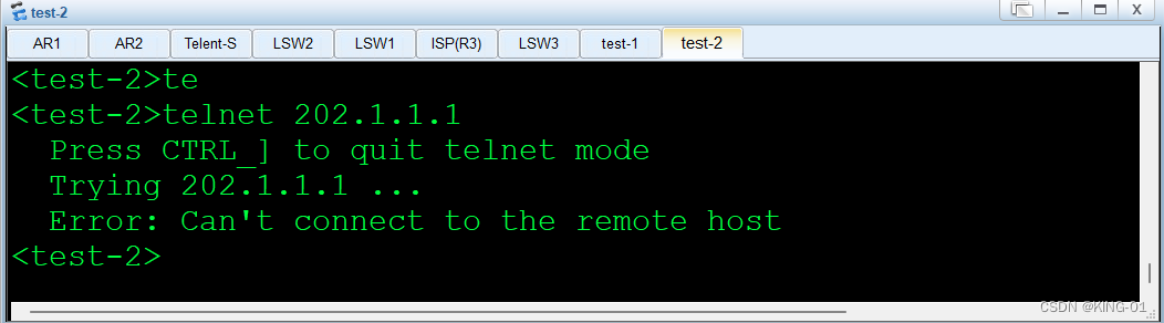
test-2测试:
<test-2>telnet 202.1.1.1
  Press CTRL_] to quit telnet mode
  Trying 202.1.1.1 ...
  Error: Can't connect to the remote host
<test-2>
8.本实验所有要求完成
9.实验思路解析
设备:RW1,RW2,RW3,R1,R2,R3,ISP,Telent-Server,test-1,test-2,PC1-PC5
1.内网基于192.168.1.0/24网段进行IP划分;
参照实验资料进行划分;
2.先为每一台设备进行改名及进行永不超时的操作,若有VLAN(广播域/局域网),也应先行配置,例下;
<Huawei>sys
[Huawei]sysnameRW1
[RW1]user-interface console 0
[RW1-ui-console0]idle-timeout 0 0
[RW1-ui-console0]quit
[RW1]vlan batch 2 3 4 /*(将交换机连接PC端的VLAN一起配置)*/
[RW1]int g0/0/2
[RW1-GigabitEthernet0/0/2]port link-type access
[RW1-GigabitEthernet0/0/2]port default vlan 2
[RW1-GigabitEthernet0/0/2]int g0/0/3
[RW1-GigabitEthernet0/0/3]port link-type access
[RW1-GigabitEthernet0/0/3]port default vlan 3
[RW1-GigabitEthernet0/0/3]int g0/0/4
[RW1-GigabitEthernet0/0/4]port link-type access
[RW1-GigabitEthernet0/0/4]port default vlan 4
[RW1-GigabitEthernet0/0/4]int g0/0/1
[RW1-GigabitEthernet0/0/1]port link-type trunk /*注意:VLAN及IP规划查看附件材料(所有trunk链路按照最少VLAN透传原则放通)*/
[RW1-GigabitEthernet0/0/1]port trunk allow-pass vlan 2 3 4
[RW1-GigabitEthernet0/0/1]quit
查看配置好的VLAN,输入以下命令:
[RW1]display vlan
3.PC1-PC4使用DHCP服务获取地址+各个虚拟子接口的封装下放网关操作;
地址池名称使用--pool 1,pool 2;
进行虚拟子接口封装下放网关与进行DHCP服务例下所示:
[r1-ui-console0]int g0/0/0.1
[r1-GigabitEthernet0/0/0.1]dot1q termination vid 2
[r1-GigabitEthernet0/0/0.1]ip address 192.168.1.30 27
[r1-GigabitEthernet0/0/0.1]int g0/0/0.2
[r1-GigabitEthernet0/0/0.2]dot1q termination vid 3
[r1-GigabitEthernet0/0/0.2]ip address 192.168.1.62 27
[r1-GigabitEthernet0/0/0.2]int g0/0/0.3
[r1-GigabitEthernet0/0/0.3]dot1q termination vid 4
[r1-GigabitEthernet0/0/0.3]ip address 192.168.1.158 27
[r1-GigabitEthernet0/0/0.3]quit
[r1]dhcp enable
[r1]ip pool 1
[r1-ip-pool-1]network 192.168.1.0 mask 27
[r1-ip-pool-1]gateway-list 192.168.1.30
[r1-ip-pool-1]dns-list 8.8.8.8
[r1-ip-pool-1]quit
[r1]int g0/0/0.1
[r1-GigabitEthernet0/0/0.1]dhcp select global
[r1-GigabitEthernet0/0/0.1]arp broadcast enable
[r1-GigabitEthernet0/0/0.1]quit
4.接下里进入到各个路由器的接口配置IP地址;
5.配置ospf实现R1与R2之间的通信;
要使R1/R2之间使用OSPF做到内网全通,单区域;
则需要:OSPF使用一条命令进行宣告(直接宣告192.168.1.0网段,PC1网段);
router-ID分别为1.1.1.1和2.2.2.2;
OSPF进程为1;
例下:
[r1]ospf 1 router-id 1.1.1.1
[r1-ospf-1]area 0
[r1-ospf-1-area-0.0.0.0]network 192.168.1.0 0.0.0.255
[r1-ospf-1-area-0.0.0.0]quit
[r1-ospf-1]quit
6.在Telnet服务器上配置缺省路由实现通信;
[Telnet Server]ip route-static 0.0.0.0 0 192.168.1.158
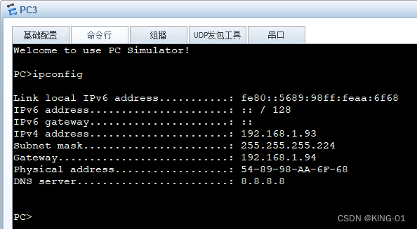
7.PC端PC1-PC4利用DHCP自动获取IP,PC5手动获取IP;
并进入到PC端操作页面输入ipconfig进行测试是否可以获取到IP;
8.测试内网的连通性;
通过Telent-Server进行ping各个网段,例下:
[Telnet-Server]ping 192.168.1.29
9.给R2配置缺省路由以此来指向外网,并进行OSPF协议,配置NAT技术,例下:
acl抓取感兴趣流量;
[R2]ip route-static 0.0.0.0 0 202.1.1.2
[R2]ospf 1 router-id 2.2.2.2
[R2-ospf-1]default-route-advertise
[R2-ospf-1]quit
[R2]acl 2000
[R2-acl-basic-2000]rule permit source 192.168.1.0 0.0.0.255
[R2-acl-basic-2000]quit
[R2]int g0/0/2
[R2-GigabitEthernet0/0/2]nat outbound 2000
[R2-GigabitEthernet0/0/2]quit
[R2]
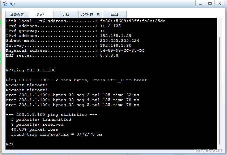
10.利用PC端cmd页面进行ping测试--内网内与外网PC5连通性;
/*实验要求:PC1不能ping到处于外网的PC5,看下面操作*/
11.test-1和test-2配置静态路由,例下:
[test-1]ip route-static 202.1.1.0 30 203.1.1.254
[test-2]ip route-static 202.1.1.0 30 203.1.1.254
查看ISP路由表,确定test-1及test-2的静态路由,命令如下;
[ISP]display ip routing-table
12.PC2-PC4可以访问PC5,PC1不行;
在R1上配置acl以此实现PC1访问不到PC5,命令如下: /*完成了第10项的实验要求*/
[R1]acl 3000
[R1-acl-adv-3000]rule deny icmp source 192.168.1.29 0 destination 203.1.1.100 0
[R1-acl-adv-3000]quit
[R1]int g0/0/0.1
[R1-GigabitEthernet0/0/0.1]traffic-filter inbound acl 3000
[R1-GigabitEthernet0/0/0.1]quit
[R1]
13.配置完成后再次利用PC端cmd页面进行ping测试 ;
14.telnet服务器的账号密码为huawei/123456;
在Telnet-Server路由器进行配置telnet服务,命令如下;
[Telnet-Server]aaa
[Telnet-Server-aaa]local-user huawei password cipher 123456 privilege level 15
[Telnet-Server-aaa]local-user huawei service-type telnet
[Telnet-Server-aaa]quit
[Telnet-Server]user-interface vty 0 4
[Telnet-Server-ui-vty0-4]authentication-mode aaa
[Telnet-Server-ui-vty0-4]quit
[Telnet-Server]
15.test-1设备可以登陆内网telent服务器;
在R2上配置端口的映射;
[R2]int g0/0/2
[R2-GigabitEthernet0/0/2]nat server protocol tcp global current-interface 23 ins
ide 192.168.1.129 23
Are you sure to continue?[Y/N]:y
[R2-GigabitEthernet0/0/2]quit
[R2]
并在test-1上测试远程登录;
<test-1>telnet 202.1.1.1
Login authentication
Username:huawei
Password:123456
16.在ISP上配置ACL拒绝test-2的包,以此来实现test-2不可登陆内网telent服务器;
/*在这里ACL我在ISP调用了,为了考虑网路的全面性,建议在R2的0/0/2接口进行配置,而不是在运营商设配配置最优的接口*/
[ISP]acl 3000
[ISP-acl-adv-3000]
[ISP-acl-adv-3000]rule deny tcp source 203.1.1.2 0 destination 202.1.1.1 0 destination-port eq 23
[ISP-acl-adv-3000]quit
[ISP]int g0/0/1
[ISP-GigabitEthernet0/0/1]traffic-filter inbound acl 3000
[ISP-GigabitEthernet0/0/1]quit
[ISP]
17.操作完第16项,再次测试test-2是否可以登录内网telent服务器;
<test-2>telnet 202.1.1.1
Trying 202.1.1.1 ...
Error: Can't connect to the remote host
18.对每个设备在用户界面< >,进行save操作,以此进行保存;


 3942
3942

 被折叠的 条评论
为什么被折叠?
被折叠的 条评论
为什么被折叠?
 到【灌水乐园】发言


