


版本:Vivado2020.2(Vitis)
任务:以 VDAM IP 为核心实现 VGA 彩条图像显示
(PS 端写入彩条数据到 DDR 通过 VDMA 读取出来输出给 VGA 进行显示)
目录
一、介绍
(1)AXI4-Stream Video 协议
AXI4-Stream Video(AXI4-Stream Video Protocol)是 ARM AMBA AXI4-Stream协议的扩展,专为视频数据流设计,用于高效传输像素数据,并携带视频时序信息(如帧同步、行同步)。VDMA 的 Stream 流数据就是以该协议传输视频图像数据。
| Video 端口 | 对应 AXI4-Stream端口 | 方向 | 描述 |
|---|---|---|---|
| DATA | TDATA | 主→从 | 视频数据(如RGB/YUV像素,宽度可配置) |
| VALID | TVALID | 主→从 | 主设备数据有效标志 |
| READY | TREADY | 从→主 | 从设备准备接收数据 |
| SOF (start of frame) | TUSER | 主→从 | 标记一帧数据的开始(帧同步) |
| EOL (end of line) | TLAST | 主→从 | 标记一行数据的结束(行同步) |

时序图如图所示:仅当 VALID=1 且 READY=1 时,DATA 在 ACLK 上升沿被采样。否则主设备需保持 DATA 直到从设备就绪。
(2)VDMA
VDMA(Video Direct Memory Access) 是专为视频数据流优化的DMA控制器,主要用于高效搬运摄像头、显示器等产生的二维帧数据。
2.1 VDMA 对比 DMA
| VDMA | DMA | |
|---|---|---|
| 设计目标 | 视频流(如摄像头、显示器) | 通用数据搬运(内存、外设间) |
| 同步信号 | 支持 VSYNC/HSYNC(帧/行同步) | 无同步信号,依赖中断或硬件触发 |
| 地址管理 | 多帧缓冲(双/三缓冲),自动切换 | 单次线性地址递增 |
| 配置复杂度 | 需设分辨率、行跨度(stride)、帧存 | 只需源/目标地址、传输长度 |
| 硬件资源 | 较多 | 较少 |
2.2 VDMA 概述
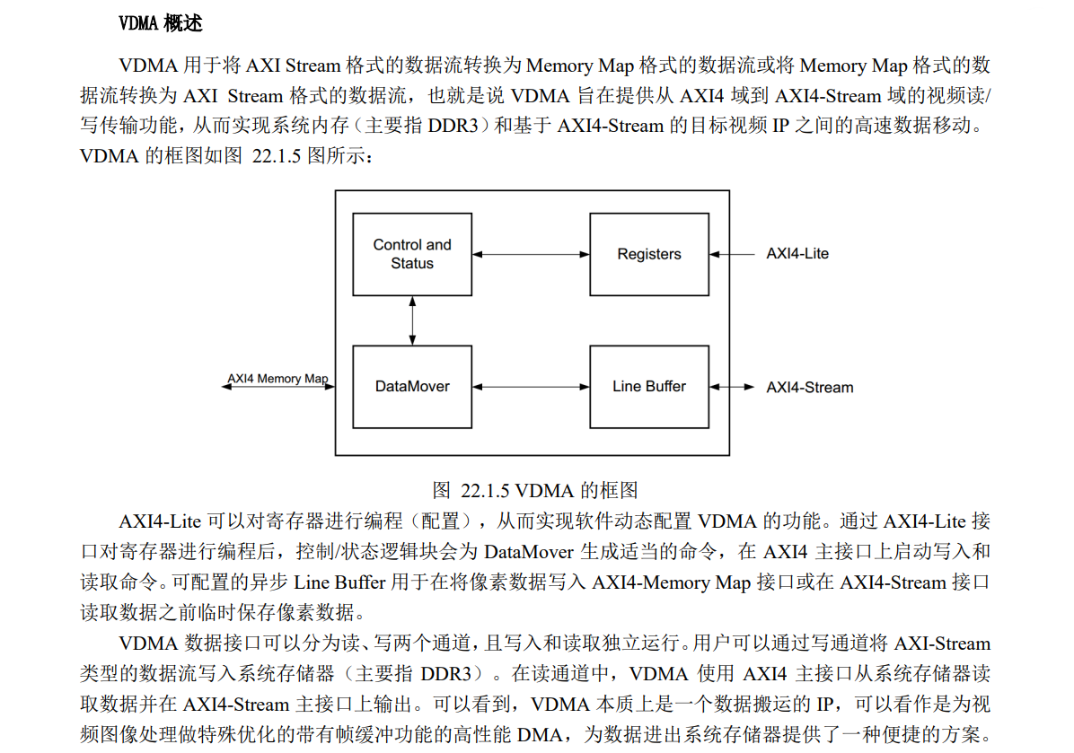
2.3 VDMA 同步锁相(Genlock)
本例只显示彩条图像,即只用一直显示一帧,没有用到这同步锁相,所以后面帧缓存配置的为1。但在用 VDMA 设计视频图像采集系统时,这一部分尤为重要。
VDMA 的同步锁相机制是确保视频数据流稳定传输的核心技术,主要用于解决视频源(如摄像头)与处理系统(如FPGA)之间的时钟域差异和帧同步对齐问题。也可以理解为实现了图像帧缓存功能,防止最后视频图像出现撕裂等等问题。其核心原理如下(摘自正点原子开发指南):
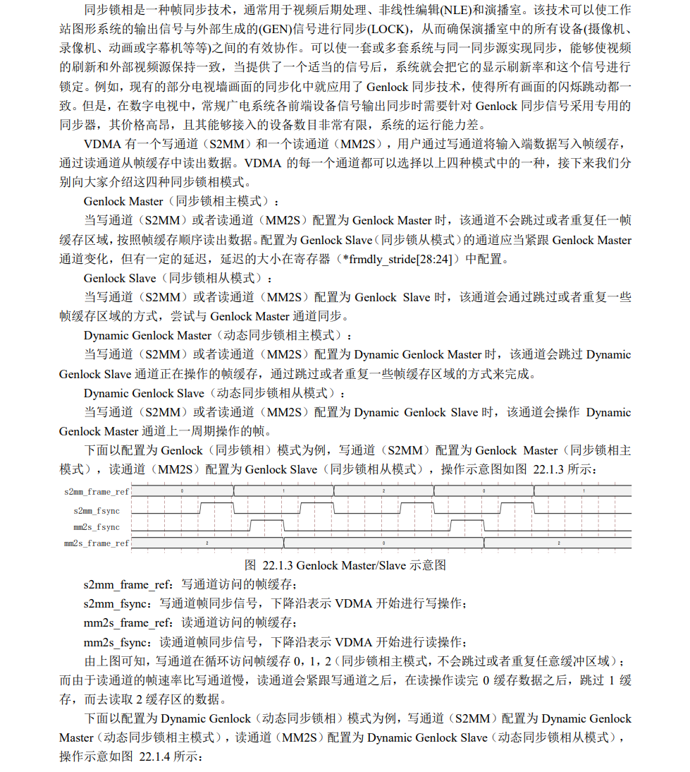
(3)AXI4-Stream to Video Out
(3、4)可参考:ZYNQ-Video out IP和Video Timing Controller IP简介
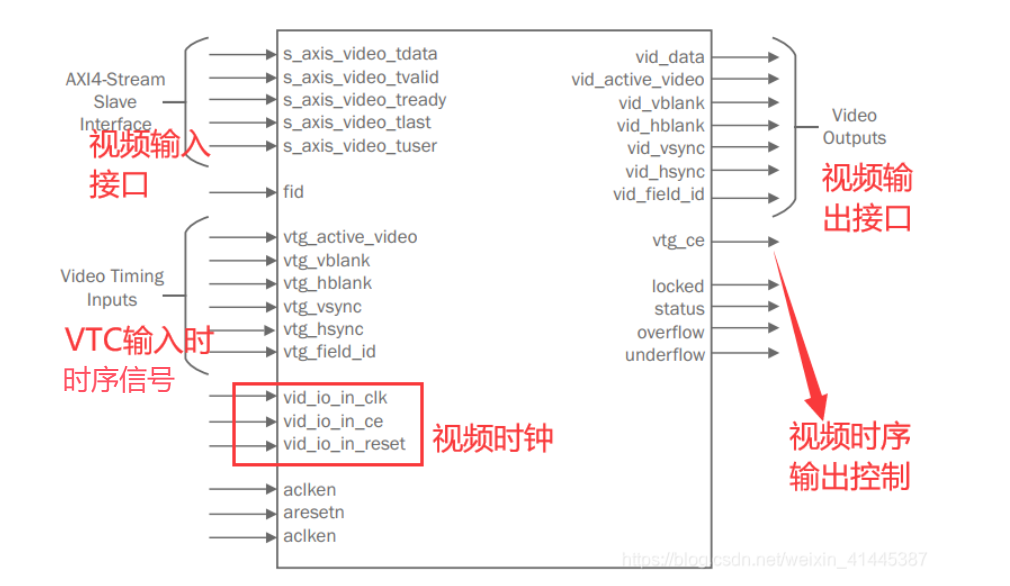
AXI4-Stream to Video Out 是一个硬件模块,用于将 AXI4-Stream 视频数据流 转换为 标准的视频输出信号(如 HDMI、DisplayPort 或 LCD 屏的并行 RGB 接口),主要完成以下功能:
| 功能 | 说明 |
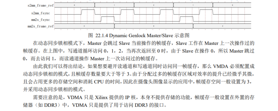
|---|---|
| 数据流转换 | 将 AXI4-Stream (Video) 协议(基于 TDATA、TVALID、TREADY 握手)转换为视频时序信号(VSYNC、HSYNC、DE、像素数据)。支持常见像素格式(如 RGB888、YUV422) |
| 时序输出 | 输入 VTC 时序信号,同视频数据输出标准的视频同步信号(VSYNC、HSYNC) |
| 数据缓冲与同步 | 使用 FIFO 或行缓冲 解决 AXI4-Stream 数据流与视频输出时钟域的差异(跨时钟域处理)。确保数据稳定输出,避免撕裂 |
Video Out 需要搭配 Video Timing Controller IP核(VTC)使用,vtg_ce 端口为 VTC 的时钟使能信号。
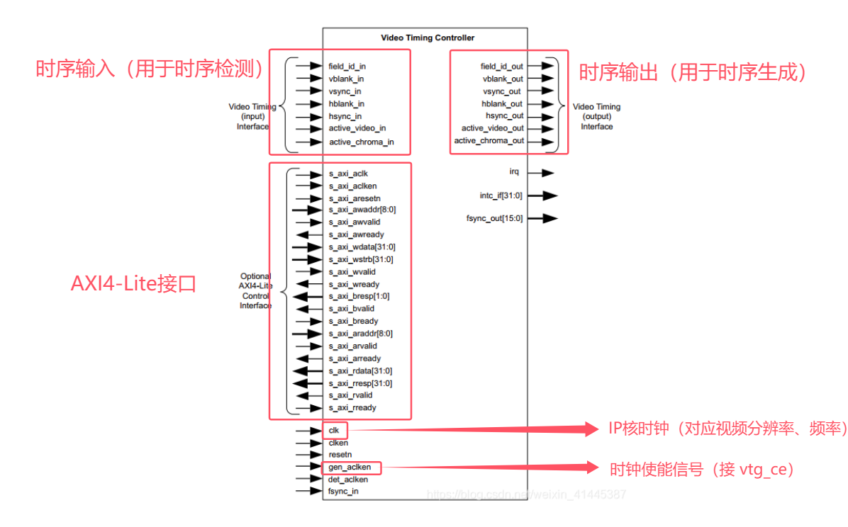
(4)Video Timing Controller
Video Timing Controller IP(VTC)是一个通用视频时序信号发生器和检测器。所有的视频系统都需要视频时序信号的管理,这些信号用于同步传输进程。VTC IP 核的功能是检测和产生这些时序信号。在该 IP 的输入端,自动检测水平和垂直同步脉冲,极性,消隐时间和活动视频像素相关时序参数;在输出端口,它产生水平和垂直消隐和同步脉冲使用的标准视频系统,包括支持可编程脉冲极性。可以通过 AXI4-Lite 接口动态配置 Video Timing Controller。
该 IP 通常与 Video in to AXI4-Stream IP 一起用于检测传入视频数据的格式和时序信息,或与AXI4-Stream to Video out IP 一起用于为视频输出设备(如视频监视器)生成输出视频时间。
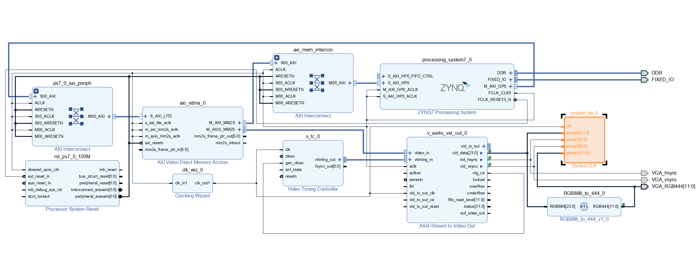
二、硬件设计
整体系统框图:
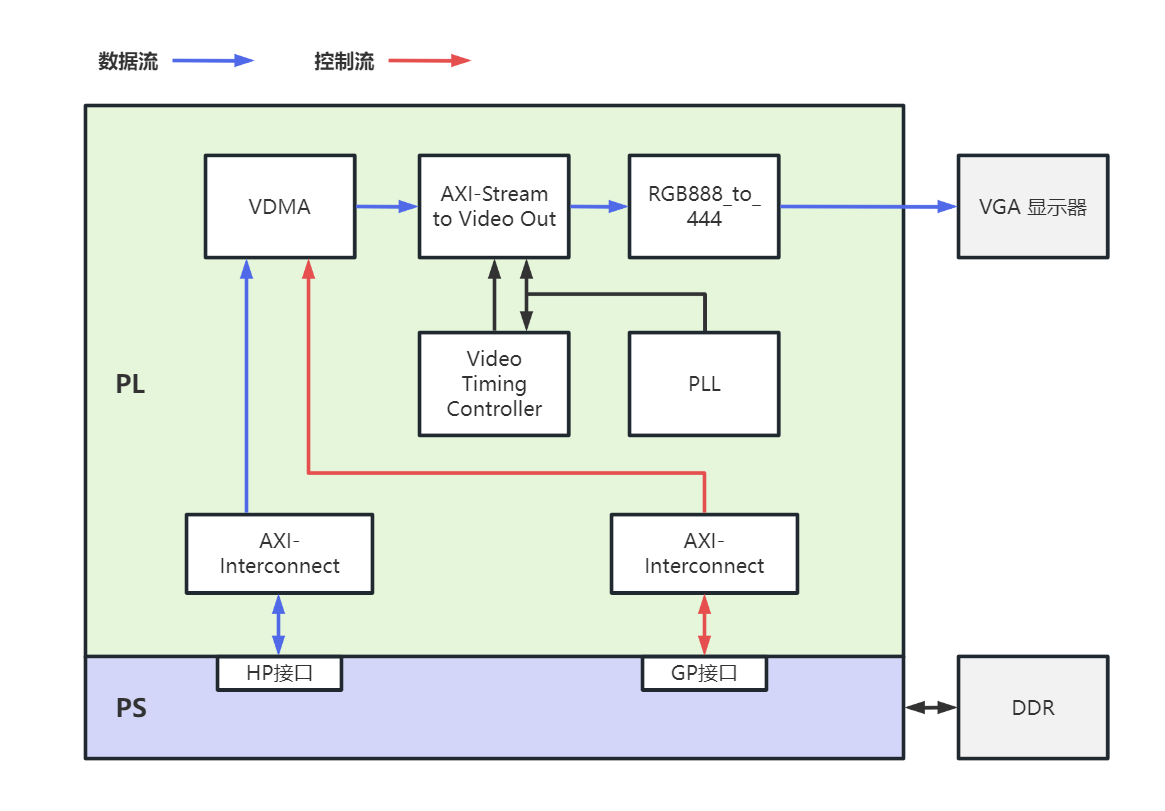
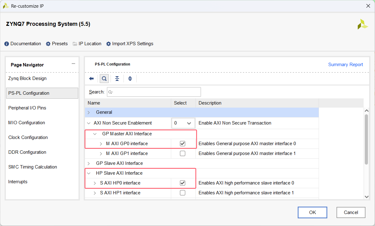
(1)ZYNQ 配置
PS 通过 GP 接口控制 VDMA,而 VDAM 使用 HP 接口与 PS 进行数据交互,所以配置 ZYNQ 时需要使用一个 GP(Master接口)和一个 HP 接口。
此外还使用到了PL时钟(100MHz)、复位、UART。
(2)VDMA 配置
针对彩条实验,只需要显示一帧彩条图像即可,所以帧缓存一帧即可,写数据通道不使用,以下表格列出了详细配置:
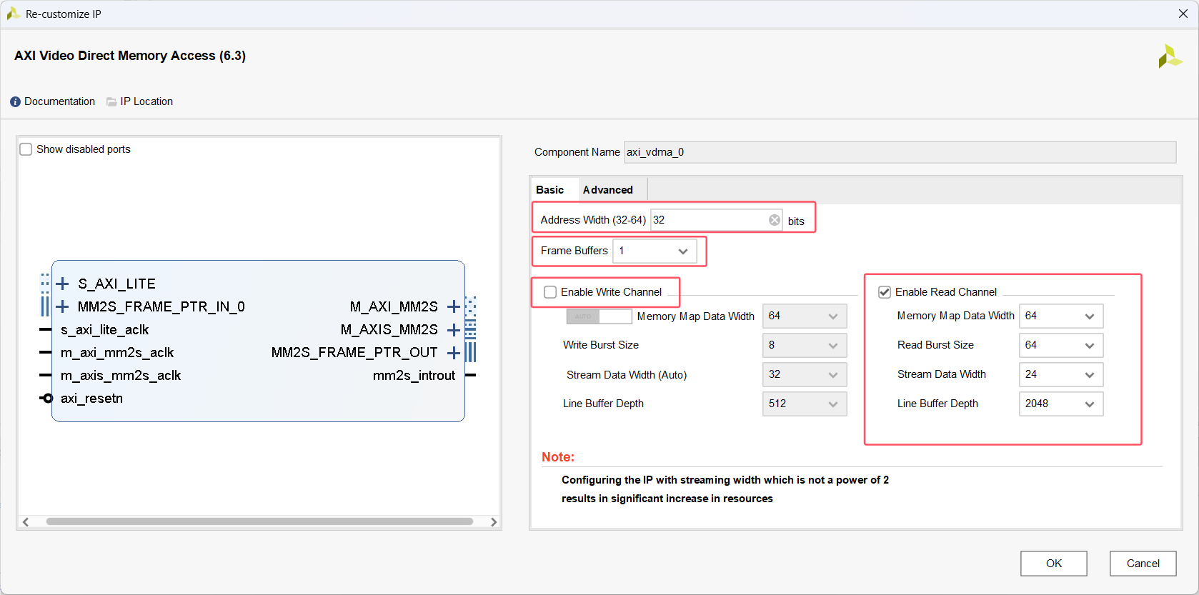
| 配置界面 | 参数名称 | 设置值/选项 | 说明 |
|---|---|---|---|
| Basic | Address Width | 32(默认) | 内存地址宽度 |
| Frame Buffers | 1 | 仅需 1 个帧缓存(彩条数据只需写入一次) | |
| Enable Read Channel | ✔️(启用) | 实验从 DDR3 读取数据,需启用读通道。 | |
| Enable Write Channel | ✖️(禁用) | 无需写入数据。 | |
| Memory Map Data Width | 64(默认) | AXI4 数据总线宽度,64 位可满足带宽需求。 | |
| Read Burst Size | 64 | 突发读取大小(范围 2~256 字节),64 平衡效率和延迟。 | |
| Stream Data Width | 24 | AXI4-Stream 数据宽度,RGB888 格式需 24 位 | |
| Line Buffer Depth | 2048 | 行缓冲深度,需结合分辨率调整,确保行缓冲能容纳一行像素数据(这里支持一行2048个像素) | |
| Advanced | GenLock Mode | 保持默认 | 本例单帧缓存+单通道,无需同步锁相配置。 |
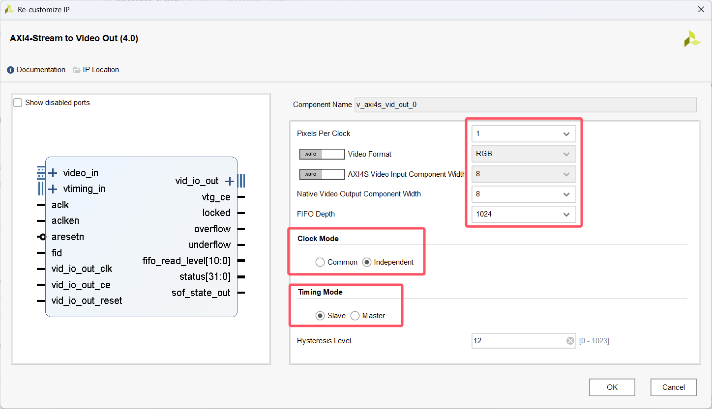
(3)Video Out 配置
| 参数名称 | 设置值/选项 | 说明 |
|---|---|---|
| Pixels Per Clock | 1 | 每时钟周期处理的像素数(自动根据分辨率适配)。 |
| Video Format | RGB | 本例采用RGB888格式,选RGB格式数据 |
| AXI4S Video Input Component Width | 8 (每通道) | AXI4-Stream 输入视频分量位宽(R/G/B各8位,共24位) |
| Native Video Output Component Width | 8 (每通道) | 输出视频分量的位宽(R/G/B各8位,总计24位) |
| FIFO Depth | 1024 | 异步 FIFO 深度(影响跨时钟域稳定性,值越大稳定能力越强) |
| Clock Mode | Independent | 输入(AXI4S)和输出(Video)时钟独立(V_TC IP提供时钟) |
| Timing Mode | Slave | - Slave(推荐):从外部输入同步信号(如VSYNC/HSYNC)。 - Master:内部生成同步信号。 |
| Hysteresis Level | 12 | FIFO 读写的滞后等级(保持默认12 个数据) |
各端口含义可参考:AXI4-Stream to Video Out模块配置(懒人版)
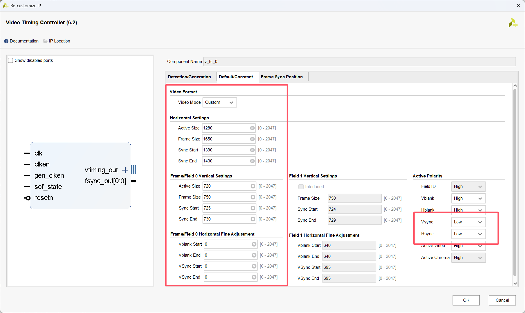
(4)VTC 配置
各端口含义可参考:Vivado VTC(video-timing-controller)模块配置(懒人版)
第一栏配置如下:
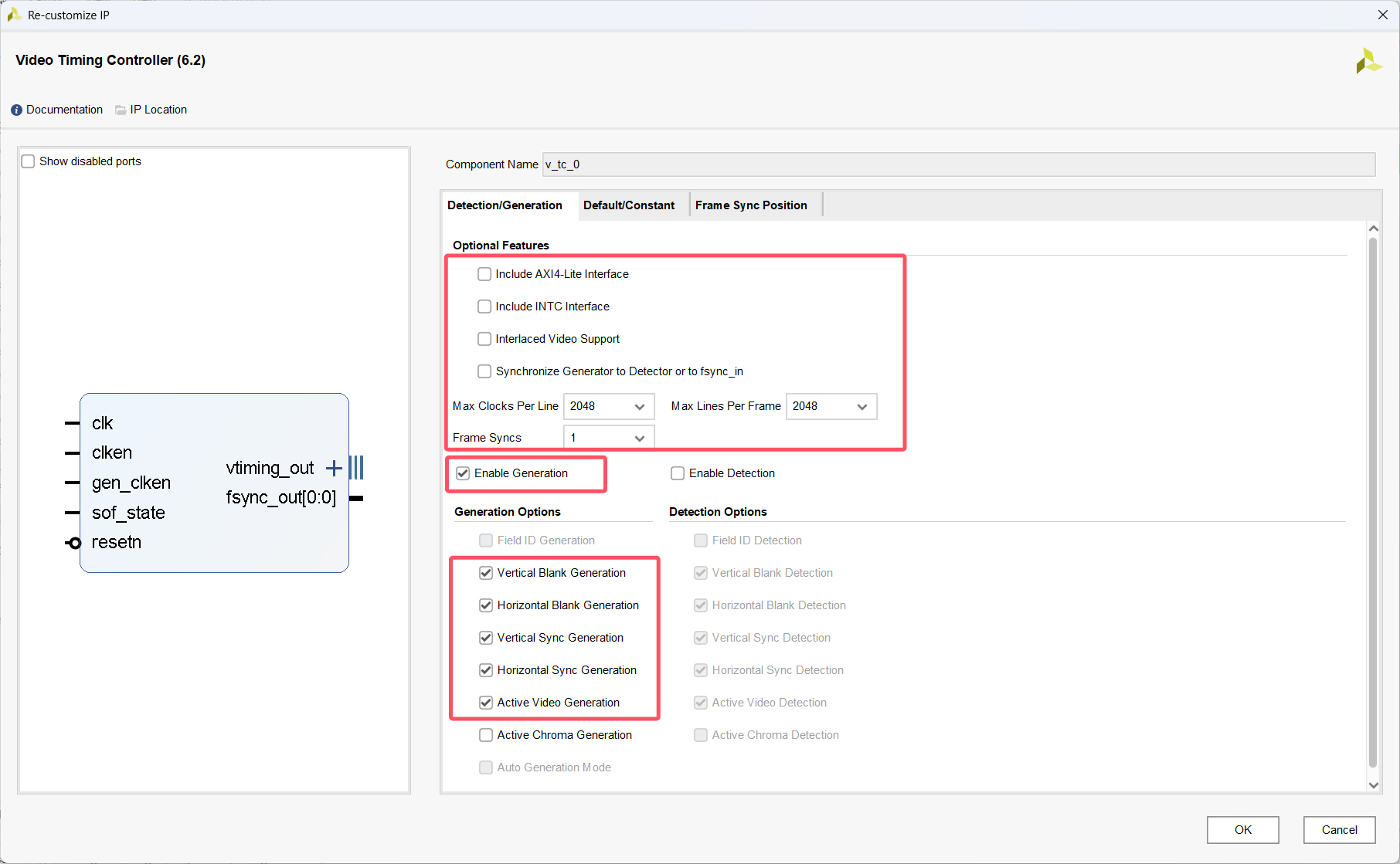
| 参数名称 | 设置值/选项 | 说明 |
|---|---|---|
| AXl4-Lite Interface | 禁用 | 不需要动态配置参数,本例用一个视频时序标准 |
| Max Clocks Per Line | 2048 | 一行最大时钟周期(根据分辨率设置,大于列数) |
| Max Lines Per Frame | 2048 | 一列最大行数(根据分辨率设置,大于行数) |
| Frame Syncs | 1 | 帧同步(保持默认) |
| Enable Generation | 启用 | 启用时序生成,输出的端口保持默认 |
| Enable Detection | 禁用 | 禁用时序检测,本例不需要 |
第二栏配置时序参数,这里选择 Custom 自定义时序参数,参数设置参考:vivado中的Video timing controller IP核参数计算方法 、 Verilog:VGA控制器 、 Video Beginner Series 16: Understanding Video Timing with the VTC IP。
本次选用 1280×720 @ 60Hz(720p),时序标准如图所示,这个表直接给出了所有参数,不过所有参数都是根据基本参数计算得到的:
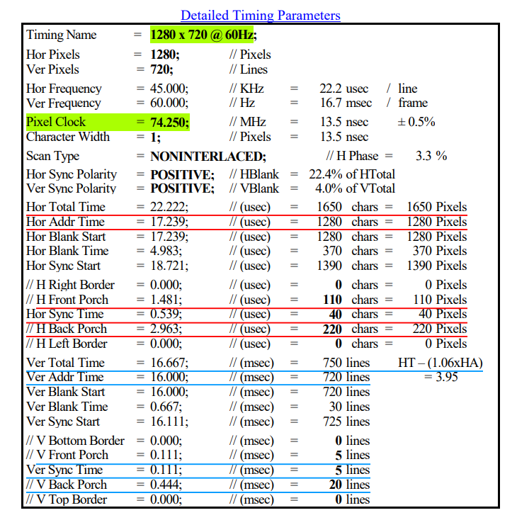
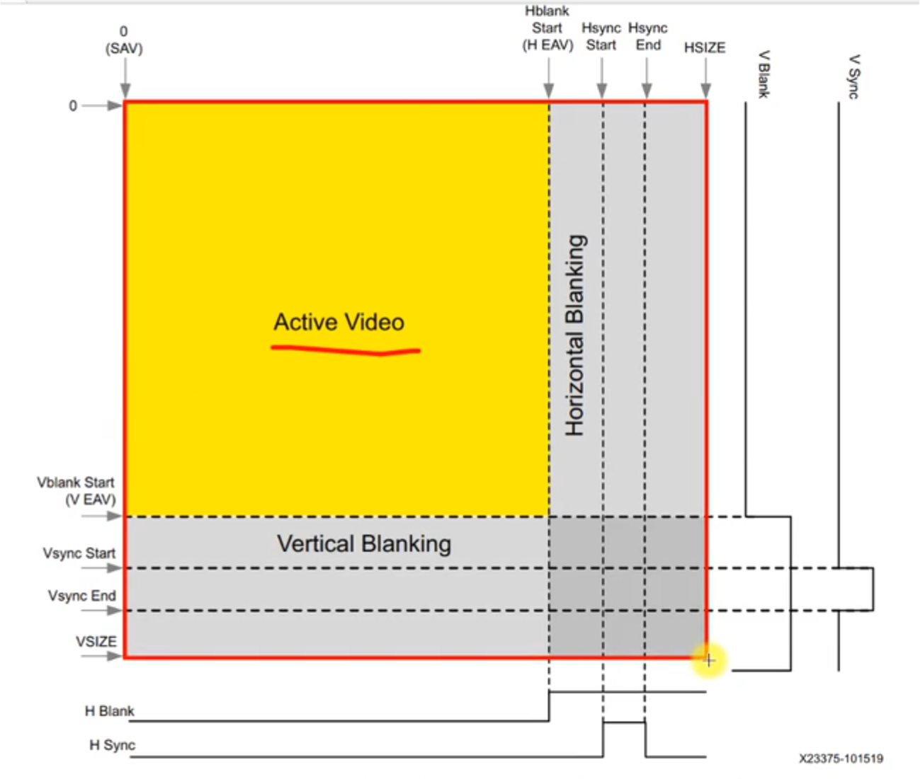
水平方向 (H):
| 参数 | 值 | 说明 |
|---|---|---|
| Active Size | 1280 | 像素数据有效区间,直接填入。 |
| Frame Size | 1650 | 即 Total Time :Active Size + Front Porch + Hsync Time + Back Porch (1280 + 110 + 40 + 220) |
| Sync Start | 1390 | Active Size + Front Porch(1280 + 110) |
| Sync End | 1430 | Active Size + Front Porch + Hsync Time(1280 + 110 + 40) |
垂直方向 (V):
| 参数 | 值 | 说明 |
|---|---|---|
| Active Size | 720 | 行数据有效区间,直接填入。 |
| Frame Size | 750 | 即 Total Time :Active Size + Front Porch + Hsync Time + Back Porch (720 + 5 + 5 + 20) |
| Sync Start | 725 | Active Size + Front Porch(720 + 5) |
| Sync End | 730 | Active Size + Front Porch + Hsync Time(720 + 5 + 5) |
最下面的调整参数一般用不到,直接给0,此外行场同步信号(hsync、vsync)极性为负(在同步信号的“有效期”内拉高,一般VGA显示器是负极性,LCD为正极性),最终配置如图所示:
(5)RGB888 to 444
我的 ZYNQ 板卡的 VGA 接口只支持 RGB444格式,所以要将 888 格式数据每一个颜色分量截取高4位输出即可,写一个组合逻辑实现的模块,再添加到BD设计中即可:
`timescale 1ns / 1ps
module RGB888_to_444(
    input  wire [23:0] RGB888,  // 24位RGB888输入 (R[23:16], G[15:8], B[7:0])
    output wire [11:0] RGB444   // 12位RGB444输出 (R[11:8], G[7:4], B[3:0])
);
    // 截取RGB888各通道的高4位,组合成RGB444
    assign RGB444 = {RGB888[23:20], RGB888[15:12], RGB888[7:4]};
endmodule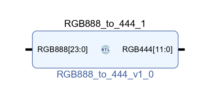
(6)连线
1. Video Out 的 vtg_ce 端口连接到 VTC 的genclk_en 端口。
2. VDMA 的 M AXIS MM2S 接口连接到 Video Out 的 video_in 接口。
3. VTC 的 vtiming_out 接口连接到 Video Out 的 vtiming_in 接口。
4. 添加一个锁相环给 VTC 产生对应的像素时钟(74.250MHz),同时给到 Video Out 视频时钟输入。输入时钟是 ZYNQ PS 端的 100MHz 时钟输出。
5. 将 Video Out 输出的 RGB888 数据端口接到 RGB888_to_444 模块的输入端口,再将 RGB888_to_444 输出端口即为 VGA接口的数据端口。 Video Out 的 H、V 同步信号输出端口为 VGA 接口的同步信号端口。
到此,主要的IP就全部配置好了,上述关键的信号端口连接情况如图所示:
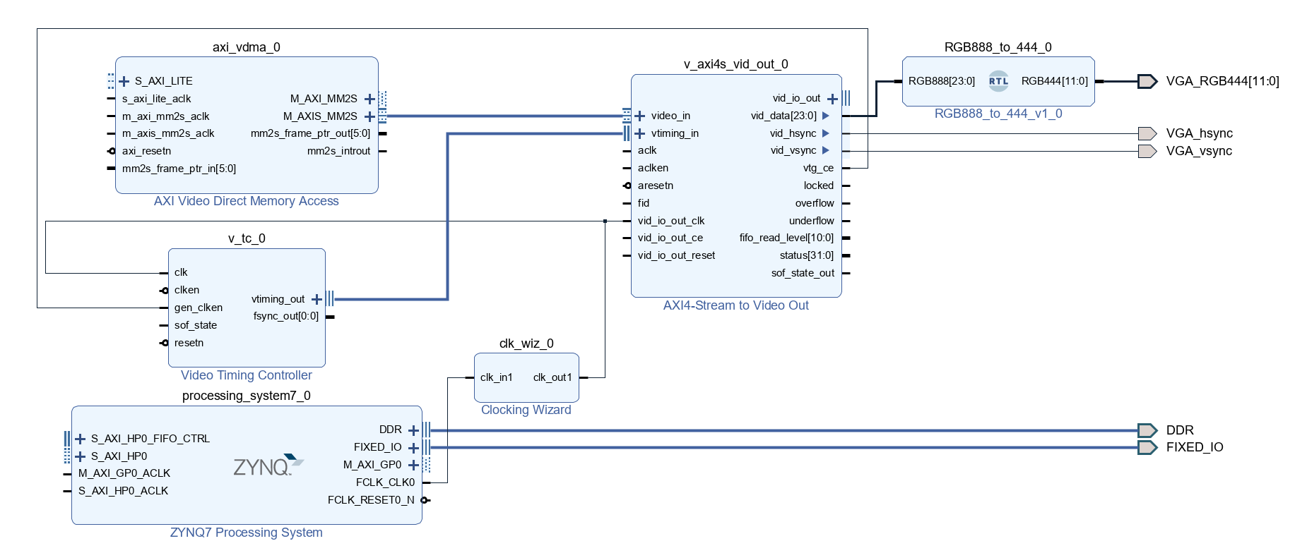
运行自动连接,(多添加了一个 ILA 用于抓取视频信号波形)最终整体 bd 设计部分如图所示:设计检查、Generate Output Products、 Create HDL Wrapper、管脚约束、Gnerate Bitstream、Export Hardware(包含比特流文件)、启动Vitis
三、软件设计
(1)导入 vdma_api.c 文件
导入 Xilinx 官方的 axi_vdma 的工程模板,选择 vdma 的示例,这里面提供了一个 vdma_api.c 文件,包含本次启动配置VDMA的 “run_triple_frame_buffer” 函数,直接套用里面的函数就不用自己慢慢写了,快速实现vdma启动和配置。
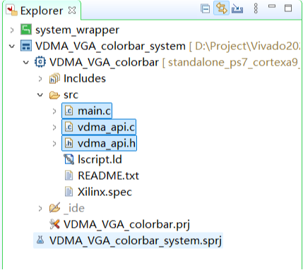
将模板中的 vdma_api.c 复制到自己工程的src目录下,并新建一个 vdma_api.h 在里面对“run_triple_frame_buffer” 函数以及 vdma_api.c 说包含的头文件进行声明。
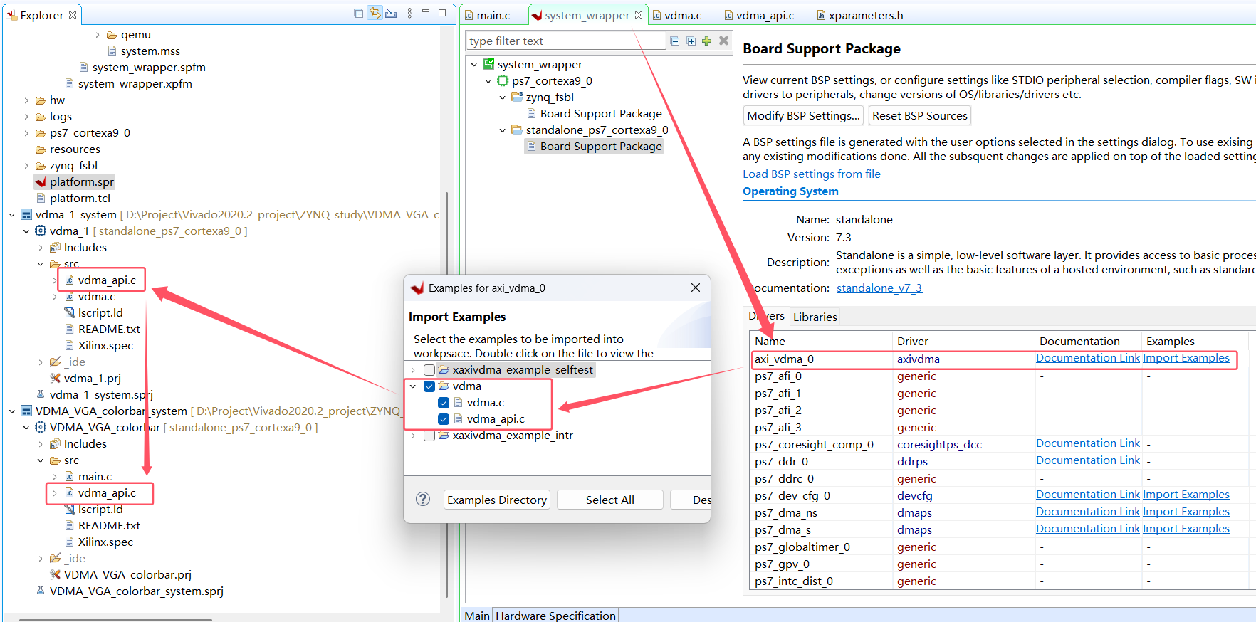
官方的 run_triple_frame_buffer 函数是同时打开 VDMA 读写通道 并进行传输的,由于本次试验不需要打开写通道(PS端写入DDR,只需要VDMA读),所以对文件内的函数作了修改(函数名称也作了修改),添加一个形参,通过函数输入的形参来判断是否打开读通道或者写通道。同时也方便后续 VDMA 配置使用。修改后的 vdma_api.c 如下:
/*****************************************************************************/
/**
 * @file vdma_api.c
 *
 * This file has high level API to configure and start the VDMA.The file assumes that:
 * The design has VDMA with both MM2S and S2MM path enable.
 * The API's has tested with hardware that has tow VDMA and MM2S to S2MM are back
 * to back connected for each VDMA.
 *
 * ***************************************************************************/
#define DEBUG_MODE		0


/******************** Include files **********************************/
#include "xaxivdma.h"
#include "xparameters.h"
#include "xil_exception.h"
#include "vdma_api.h"

/******************** Data structure Declarations *****************************/

typedef struct vdma_handle
{
	/* The device ID of the VDMA */
	unsigned int device_id;
	/* The state variable to keep track if the initialization is done*/
	unsigned int init_done;
	/** The XAxiVdma driver instance data. */
	XAxiVdma* InstancePtr;
	/* The XAxiVdma_DmaSetup structure contains all the necessary information to
	 * start a frame write or read. */
	XAxiVdma_DmaSetup ReadCfg;
	XAxiVdma_DmaSetup WriteCfg;
	/* Horizontal size of frame */
	unsigned int hsize;
	/* Vertical size of frame */
	unsigned int vsize;
	/* Buffer address from where read and write will be done by VDMA */
	unsigned int buffer_address;
	/* Flag to tell VDMA to interrupt on frame completion*/
	unsigned int enable_frm_cnt_intr;
	/* The counter to tell VDMA on how many frames the interrupt should happen*/
	unsigned int number_of_frame_count;
}vdma_handle;

/******************** Constant Definitions **********************************/

/*
 * Device related constants. These need to defined as per the HW system.
 */
vdma_handle vdma_context[XPAR_XAXIVDMA_NUM_INSTANCES];
static unsigned int context_init=0;

/******************* Function Prototypes ************************************/

static int ReadSetup(vdma_handle *vdma_context);
static int WriteSetup(vdma_handle *vdma_context);
static int StartTransfer(XAxiVdma *InstancePtr,vdma_run_mode mode);


/*****************************************************************************/
/**
*
* run_vdma_frame_buffer API
*
* This API is the interface between application and other API. When application will call
* this API with right argument, This API will call rest of the API to configure the read
* and write path of VDMA,based on ID. After that it will start both the read and write path
* of VDMA
*
* @param	InstancePtr is the handle to XAxiVdma data structure.
* @param	DeviceId is the device ID of current VDMA
* @param	hsize is the horizontal size of the frame. It will be in Pixels.
* 		The actual size of frame will be calculated by multiplying this
* 		with tdata width.
* @param 	vsize is the Vertical size of the frame.
* @param	buf_base_addr is the buffer address where frames will be written
*		and read by VDMA.
* @param 	number_frame_count specifies after how many frames the interrupt
*		should come.
* @param 	enable_frm_cnt_intr is for enabling frame count interrupt
*		when set to 1.
* @param    select to sets up the read channel,the write channel or both of
*       the read and write channel.
* @return
*		- XST_SUCCESS if example finishes successfully
*		- XST_FAILURE if example fails.
*
******************************************************************************/
int run_vdma_frame_buffer(XAxiVdma* InstancePtr, int DeviceId, int hsize,
		int vsize, int buf_base_addr, int number_frame_count,
		int enable_frm_cnt_intr,vdma_run_mode mode)
{
	int Status,i;
	XAxiVdma_Config *Config;
	XAxiVdma_FrameCounter FrameCfgPtr;

	/* This is one time initialization of state machine context.
	 * In first call it will be done for all VDMA instances in the system.
	 */
	if(context_init==0) {
		for(i=0; i < XPAR_XAXIVDMA_NUM_INSTANCES; i++) {
			vdma_context[i].InstancePtr = NULL;
			vdma_context[i].device_id = -1;
			vdma_context[i].hsize = 0;
			vdma_context[i].vsize = 0;
			vdma_context[i].init_done = 0;
			vdma_context[i].buffer_address = 0;
			vdma_context[i].enable_frm_cnt_intr = 0;
			vdma_context[i].number_of_frame_count = 0;

		}
		context_init = 1;
	}

	/* The below initialization will happen for each VDMA. The API argument
	 * will be stored in internal data structure
	 */

	/* The information of the XAxiVdma_Config comes from hardware build.
	 * The user IP should pass this information to the AXI DMA core.
	 */
	Config = XAxiVdma_LookupConfig(DeviceId);
	if (!Config) {
		xil_printf("No video DMA found for ID %d\r\n",DeviceId );
		return XST_FAILURE;
	}

	if(vdma_context[DeviceId].init_done ==0) {
		vdma_context[DeviceId].InstancePtr = InstancePtr;

		/* Initialize DMA engine */
		Status = XAxiVdma_CfgInitialize(vdma_context[DeviceId].InstancePtr,
						Config, Config->BaseAddress);
		if (Status != XST_SUCCESS) {
			xil_printf("Configuration Initialization failed %d\r\n",
					Status);
			return XST_FAILURE;
		}

		vdma_context[DeviceId].init_done = 1;
	}

	vdma_context[DeviceId].device_id = DeviceId;
	vdma_context[DeviceId].vsize = vsize;

	vdma_context[DeviceId].buffer_address = buf_base_addr;
	vdma_context[DeviceId].enable_frm_cnt_intr = enable_frm_cnt_intr;
	vdma_context[DeviceId].number_of_frame_count = number_frame_count;
	vdma_context[DeviceId].hsize = hsize * (Config->Mm2SStreamWidth>>3);

	/* Setup the write channel */
	if ((mode == BOTH) || (mode == ONLY_WRITE)) {
		Status = WriteSetup(&vdma_context[DeviceId]);
		if (Status != XST_SUCCESS) {
			xil_printf("Write channel setup failed %d\r\n", Status);
			if (Status == XST_VDMA_MISMATCH_ERROR)
				xil_printf("DMA Mismatch Error\r\n");
			return XST_FAILURE;
		}
	}

	/* Setup the read channel */
	if ((mode == BOTH) || (mode == ONLY_READ)) {
		Status = ReadSetup(&vdma_context[DeviceId]);
		if (Status != XST_SUCCESS) {
			xil_printf("Read channel setup failed %d\r\n", Status);
			if (Status == XST_VDMA_MISMATCH_ERROR)
				xil_printf("DMA Mismatch Error\r\n");
			return XST_FAILURE;
		}
	}

	/* The frame counter interrupt is enabled, setting VDMA for same */
	if(vdma_context[DeviceId].enable_frm_cnt_intr) {
		FrameCfgPtr.ReadDelayTimerCount = 1;
		FrameCfgPtr.ReadFrameCount = number_frame_count;
		FrameCfgPtr.WriteDelayTimerCount = 1;
		FrameCfgPtr.WriteFrameCount = number_frame_count;

		XAxiVdma_SetFrameCounter(vdma_context[DeviceId].InstancePtr,&FrameCfgPtr);
		/* Enable DMA read and write channel interrupts. The configuration for interrupt
		 * controller will be done by application	 */
		XAxiVdma_IntrEnable(vdma_context[DeviceId].InstancePtr,
				XAXIVDMA_IXR_ERROR_MASK |
				XAXIVDMA_IXR_FRMCNT_MASK,XAXIVDMA_WRITE);
		XAxiVdma_IntrEnable(vdma_context[DeviceId].InstancePtr,
				XAXIVDMA_IXR_ERROR_MASK |
				XAXIVDMA_IXR_FRMCNT_MASK,XAXIVDMA_READ);
	} else	{
		/* Enable DMA read and write channel interrupts. The configuration for interrupt
		* controller will be done by application	 */
		XAxiVdma_IntrEnable(vdma_context[DeviceId].InstancePtr,
					XAXIVDMA_IXR_ERROR_MASK,XAXIVDMA_WRITE);
		XAxiVdma_IntrEnable(vdma_context[DeviceId].InstancePtr,
					XAXIVDMA_IXR_ERROR_MASK ,XAXIVDMA_READ);
	}

	/* Start the DMA engine to transfer */
	Status = StartTransfer(vdma_context[DeviceId].InstancePtr,mode);
	if (Status != XST_SUCCESS) {
		if(Status == XST_VDMA_MISMATCH_ERROR)
			xil_printf("DMA Mismatch Error\r\n");
		return XST_FAILURE;
	}
#if DEBUG_MODE
	xil_printf("Code is in Debug mode, Make sure that buffer addresses are at valid memory \r\n");
	xil_printf("In triple mode, there has to be six consecutive buffers for Debug mode \r\n");
	{
		u32 pixels,j,Addr = vdma_context[DeviceId].buffer_address;
		u8 *dst,*src;
		u32 total_pixel = vdma_context[DeviceId].WriteCfg.Stride * vdma_context[DeviceId].vsize;
		src = (unsigned char *)Addr;
		dst = (unsigned char *)Addr + (total_pixel * vdma_context->InstancePtr->MaxNumFrames);

		for(j=0;j<vdma_context->InstancePtr->MaxNumFrames;j++) {
			for(pixels=0;pixels<total_pixel;pixels++) {
				if(src[pixels] != dst[pixels]) {
					xil_printf("VDMA transfer failed: SRC=0x%x, DST=0x%x\r\n",
							src[pixels],dst[pixels]);
					exit(-1);
				}
			}
			src = src + total_pixel;
			dst = dst + total_pixel;
		}
	}
	xil_printf("VDMA transfer is happening and checked for 3 frames \r\n");
#endif

	return XST_SUCCESS;
}

/*****************************************************************************/
/**
*
* This function sets up the read channel
*
* @param	vdma_context is the context pointer to the VDMA engine.
*
* @return	XST_SUCCESS if the setup is successful, XST_FAILURE otherwise.
*
* @note		None.
*
******************************************************************************/
static int ReadSetup(vdma_handle *vdma_context)
{
	int Index;
	u32 Addr;
	int Status;

	vdma_context->ReadCfg.VertSizeInput = vdma_context->vsize;
	vdma_context->ReadCfg.HoriSizeInput = vdma_context->hsize;

	vdma_context->ReadCfg.Stride = vdma_context->hsize;
	vdma_context->ReadCfg.FrameDelay = 0;  /* This example does not test frame delay */

	vdma_context->ReadCfg.EnableCircularBuf = 1;
	vdma_context->ReadCfg.EnableSync = 1;  /* Gen-Lock */

	vdma_context->ReadCfg.PointNum = 0;
	vdma_context->ReadCfg.EnableFrameCounter = 0; /* Endless transfers */

	vdma_context->ReadCfg.FixedFrameStoreAddr = 0; /* We are not doing parking */
	/* Configure the VDMA is per fixed configuration, This configuration is being used by majority
	 * of customer. Expert users can play around with this if they have different configurations */

	Status = XAxiVdma_DmaConfig(vdma_context->InstancePtr, XAXIVDMA_READ, &vdma_context->ReadCfg);
	if (Status != XST_SUCCESS) {
		xil_printf("Read channel config failed %d\r\n", Status);
		return XST_FAILURE;
	}

	/* Initialize buffer addresses
	 *
	 * These addresses are physical addresses
	 */
	Addr = vdma_context->buffer_address;

	for(Index = 0; Index < vdma_context->InstancePtr->MaxNumFrames; Index++) {
		vdma_context->ReadCfg.FrameStoreStartAddr[Index] = Addr;

		/* Initializing the buffer in case of Debug mode */

#if DEBUG_MODE
		{
			u32 i;
			u8 *src;
			u32 total_pixel = vdma_context->ReadCfg.Stride * vdma_context->vsize;
			src = (unsigned char *)Addr;
			xil_printf("Read Buffer %d address: 0x%x \r\n",Index,Addr);
			for(i=0;i<total_pixel;i++)
			{
				src[i] = i & 0xFF;
			}
		}
#endif
		Addr +=  vdma_context->hsize * vdma_context->vsize;
	}

	/* Set the buffer addresses for transfer in the DMA engine
	 * The buffer addresses are physical addresses
	 */
	Status = XAxiVdma_DmaSetBufferAddr(vdma_context->InstancePtr, XAXIVDMA_READ,
			vdma_context->ReadCfg.FrameStoreStartAddr);
	if (Status != XST_SUCCESS) {
		xil_printf(
			"Read channel set buffer address failed %d\r\n", Status);

		return XST_FAILURE;
	}

	return XST_SUCCESS;
}

/*****************************************************************************/
/**
*
* This function sets up the write channel
*
* @param	dma_context is the context pointer to the VDMA engine..
*
* @return	XST_SUCCESS if the setup is successful, XST_FAILURE otherwise.
*
* @note		None.
*
******************************************************************************/
static int WriteSetup(vdma_handle *vdma_context)
{
	int Index;
	u32 Addr;
	int Status;

	vdma_context->WriteCfg.VertSizeInput = vdma_context->vsize;
	vdma_context->WriteCfg.HoriSizeInput = vdma_context->hsize;

	vdma_context->WriteCfg.Stride = vdma_context->hsize;
	vdma_context->WriteCfg.FrameDelay = 0;  /* This example does not test frame delay */

	vdma_context->WriteCfg.EnableCircularBuf = 1;
	vdma_context->WriteCfg.EnableSync = 1;  /*  Gen-Lock */

	vdma_context->WriteCfg.PointNum = 0;
	vdma_context->WriteCfg.EnableFrameCounter = 0; /* Endless transfers */

	vdma_context->WriteCfg.FixedFrameStoreAddr = 0; /* We are not doing parking */
	/* Configure the VDMA is per fixed configuration, This configuration
	 * is being used by majority of customers. Expert users can play around
	 * with this if they have different configurations
	 */

	Status = XAxiVdma_DmaConfig(vdma_context->InstancePtr, XAXIVDMA_WRITE, &vdma_context->WriteCfg);
	if (Status != XST_SUCCESS) {
		xil_printf(
			"Write channel config failed %d\r\n", Status);

		return Status;
	}

	/* Initialize buffer addresses
	 *
	 * Use physical addresses
	 */
	Addr = vdma_context->buffer_address;
	/* If Debug mode is enabled write frame is shifted 3 Frames
	 * store ahead to compare read and write frames
	 */
#if DEBUG_MODE
	Addr = Addr + vdma_context->InstancePtr->MaxNumFrames * \
			(vdma_context->WriteCfg.Stride * vdma_context->vsize);
#endif

	for(Index = 0; Index < vdma_context->InstancePtr->MaxNumFrames; Index++) {
		vdma_context->WriteCfg.FrameStoreStartAddr[Index] = Addr;
#if DEBUG_MODE
		xil_printf("Write Buffer %d address: 0x%x \r\n",Index,Addr);
#endif

		Addr += (vdma_context->hsize * vdma_context->vsize);
	}

	/* Set the buffer addresses for transfer in the DMA engine */
	Status = XAxiVdma_DmaSetBufferAddr(vdma_context->InstancePtr,
			XAXIVDMA_WRITE,
			vdma_context->WriteCfg.FrameStoreStartAddr);
	if (Status != XST_SUCCESS) {
		xil_printf("Write channel set buffer address failed %d\r\n",
				Status);
		return XST_FAILURE;
	}

	/* Clear data buffer
	 */
#if DEBUG_MODE
	memset((void *)vdma_context->buffer_address, 0,
			vdma_context->ReadCfg.Stride * vdma_context->ReadCfg.VertSizeInput * vdma_context->InstancePtr->MaxNumFrames);
#endif
	return XST_SUCCESS;
}

/*****************************************************************************/
/**
*
* This function starts the DMA transfers. Since the DMA engine is operating
* in circular buffer mode, video frames will be transferred continuously.
*
* @param	InstancePtr points to the DMA engine instance
*
* @return
*		- XST_SUCCESS if both read and write start successfully
*		- XST_FAILURE if one or both directions cannot be started
*
* @note		None.
*
******************************************************************************/
static int StartTransfer(XAxiVdma *InstancePtr,vdma_run_mode mode)
{
	int Status;
	if ((mode == BOTH) || (mode == ONLY_WRITE)) {
		/* Start the write channel of VDMA */
		Status = XAxiVdma_DmaStart(InstancePtr, XAXIVDMA_WRITE);
		if (Status != XST_SUCCESS) {
			xil_printf("Start Write transfer failed %d\r\n", Status);
			return XST_FAILURE;
		}
	}
	/* Start the Read channel of VDMA */
	if ((mode == BOTH) || (mode == ONLY_READ)) {
		Status = XAxiVdma_DmaStart(InstancePtr, XAXIVDMA_READ);
		if (Status != XST_SUCCESS) {
			xil_printf("Start read transfer failed %d\r\n", Status);
			return XST_FAILURE;
		}
	}
	return XST_SUCCESS;
}
所新建的 vdma_api.h 文件如下:
#ifndef VDMA_API_H_
#define VDMA_API_H_

/* ------------------------------------------------------------ */
/*				Include File Definitions						*/
/* ------------------------------------------------------------ */

#include "xaxivdma.h"
#include "xparameters.h"
#include "xil_exception.h"

/* ------------------------------------------------------------ */
/*					General Type Declarations					*/
/* ------------------------------------------------------------ */

typedef enum
{
	ONLY_READ=1,    //VDMA只开启读通道
	ONLY_WRITE,     //VDMA只开启写通道
	BOTH            //同时开启VDMA写通道和读通道
}vdma_run_mode;

/* ------------------------------------------------------------ */
/*					Procedure Declarations						*/
/* ------------------------------------------------------------ */
int run_vdma_frame_buffer(XAxiVdma* InstancePtr, int DeviceId, int hsize,
		int vsize, int buf_base_addr, int number_frame_count,
		int enable_frm_cnt_intr,vdma_run_mode mode);
/* ------------------------------------------------------------ */

/************************************************************************/

#endif /* VDMA_API_H_ */
之后在 main.c 中 #include “vdma_api.h” 使用 “run_triple_frame_buffer” 函数即可
(2)main.c
#include "stdio.h"
#include "xil_printf.h"
#include "xparameters.h"
#include "xil_cache.h"
#include "xaxivdma.h"
#include "vdma_api.h"

//======================宏定义======================//

#define VDMA_ID			XPAR_AXIVDMA_0_DEVICE_ID		//VDMA器件ID
#define DDR_BASE_ADDR   XPAR_PS7_DDR_0_S_AXI_BASEADDR	//DDR的基地址(在xparameters.h或lscript.ld查看)
#define MEM_BASE_ADDR	(DDR_BASE_ADDR + 0x01000000)	//DDR中存储数据缓存的基地址(确保在堆栈已使用DDR范围之后,lscript.ld查看)
#define IMG_WIDTH		1280	//图像水平宽度
#define IMG_HIGHT		720		//图像垂直高度
#define PIXEL_BYTE		3		//一个像素数据所占字节(RGB888 3字节)

//==================函数、变量声明==================//

XAxiVdma Vdma;							//VDMA驱动实例
u8 *IMG_Buffer = (u8 *)MEM_BASE_ADDR;	//定义指针并指向数据存储区(一个1字节)
static void Write_Colorbar();    		//向DDR数据缓存区域写数据

//======================主函数======================//
int main()
{
	xil_printf("VDMA VGA Colorbar Test\r\n");

	//配置并启动VDMA:(本例未使用中断)
	//(VDMA实例指针,器件ID,图像宽度,图像高度,帧缓存起始地址,中断帧计数(传输多少帧产生中断),中断使能,读写模式)
	run_vdma_frame_buffer(&Vdma, VDMA_ID, IMG_WIDTH, IMG_HIGHT, (int)IMG_Buffer, 0, 0, ONLY_READ);

	//向DDR数据缓存区域写数据(写彩条图像)
	Write_Colorbar();

	while(1)
	return 0;
}

//=============向DDR数据缓存区域写数据==============//
void Write_Colorbar()
{
    u8 RGB_r, RGB_g, RGB_b;
    int x, y, addr;
    int segment_width = IMG_WIDTH / 7;  // 每种颜色占1/7宽度

    // 向DDR缓存区域写像素数据(RGB888)
    for(y = 0; y < IMG_HIGHT; y++) {
        for(x = 0; x < IMG_WIDTH; x++) {
            // 根据x坐标确定颜色
            if(x < segment_width * 1) {        // 红色
                RGB_r = 0xFF; RGB_g = 0x00; RGB_b = 0x00;
            }
            else if(x < segment_width * 2) {   // 橙色
                RGB_r = 0xFF; RGB_g = 0x4F; RGB_b = 0x00;
            }
            else if(x < segment_width * 3) {   // 黄色
                RGB_r = 0xFF; RGB_g = 0xBF; RGB_b = 0x00;
            }
            else if(x < segment_width * 4) {   // 绿色
                RGB_r = 0x00; RGB_g = 0xFF; RGB_b = 0x00;
            }
            else if(x < segment_width * 5) {   // 青色
                RGB_r = 0x00; RGB_g = 0xFF; RGB_b = 0xFF;
            }
            else if(x < segment_width * 6) {   // 蓝色
                RGB_r = 0x00; RGB_g = 0x00; RGB_b = 0xFF;
            }
            else {                             // 紫色
                RGB_r = 0x7F; RGB_g = 0x00; RGB_b = 0xFF;
            }

            addr = y * (IMG_WIDTH * PIXEL_BYTE) + x * PIXEL_BYTE;
            IMG_Buffer[addr + 0] = RGB_b;  // B
            IMG_Buffer[addr + 1] = RGB_g;  // G
            IMG_Buffer[addr + 2] = RGB_r;  // R
        }
    }

    // 刷新Cache,数据更新至内存
    Xil_DCacheFlush();
    xil_printf("Colorbar data ready\r\n");
}
四、效果
(1)VGA 彩条
VGA 显示器上的彩条为 “红橙黄绿青蓝紫” 如图所示:

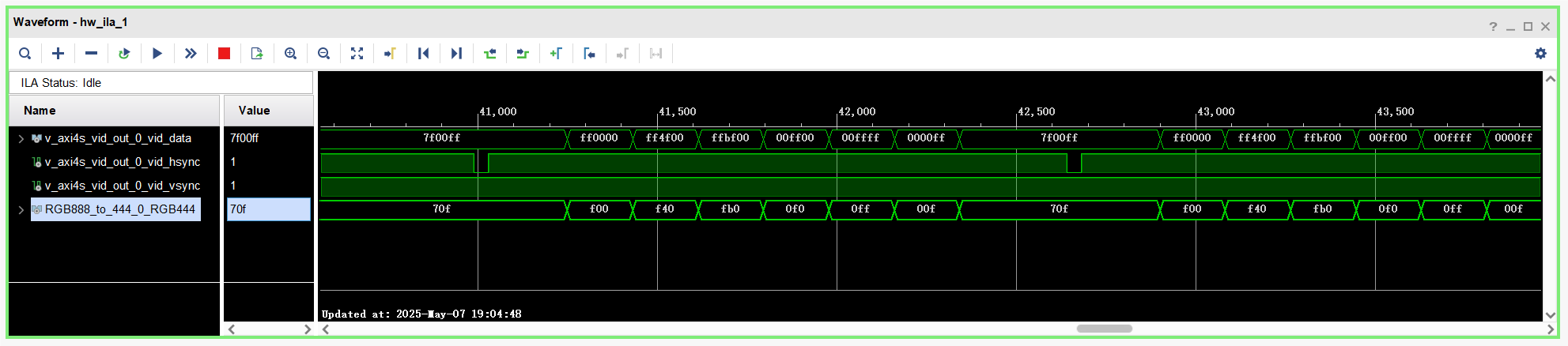
(2)ILA 抓取波形
数据较多只采样了前半部分,触发条件为Vsync 下降沿,时序参数都与视频时序标准一致。
第一幅图是抓取的整体波形:可以看到 V、H 同步信号都为负极性,在 Vsync 信号同步持续5行,同步后被拉高,经过20行的场后沿区间后开始传输有效视频数据。
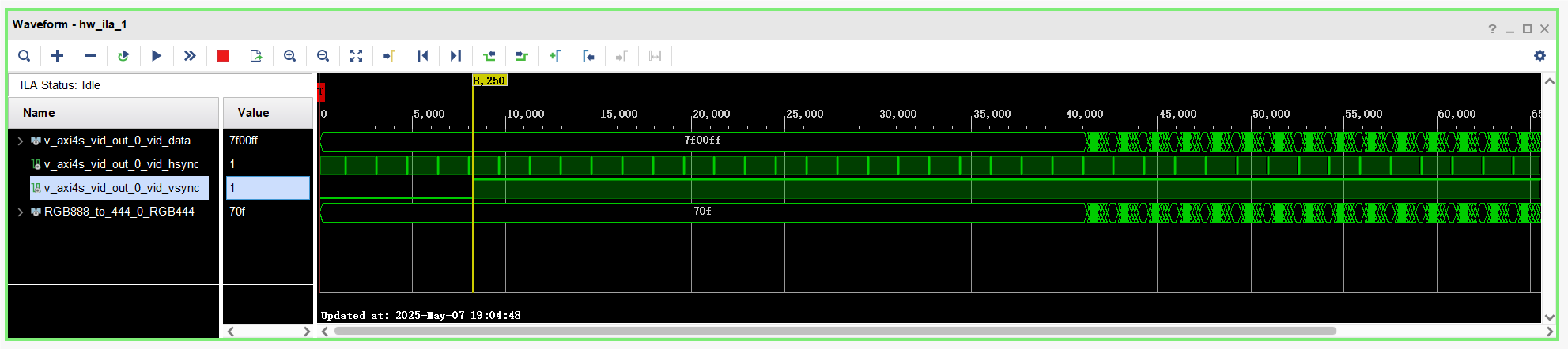
第二幅图是放大到一行的波形:在 Hsync 信号同步持续40个像素时钟,同步后被拉高,经过220个像素时钟的行后沿区间后开始传输一行数据(图里忘标像素时钟了,实际数了并确认过),可以看到数据分为七段一次对应彩条数据。


 1050
1050

 被折叠的 条评论
为什么被折叠?
被折叠的 条评论
为什么被折叠?
 到【灌水乐园】发言


