


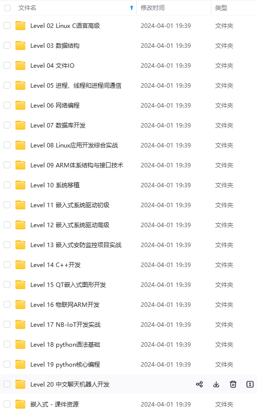
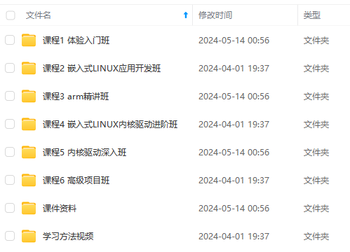
既有适合小白学习的零基础资料,也有适合3年以上经验的小伙伴深入学习提升的进阶课程,涵盖了95%以上物联网嵌入式知识点,真正体系化!
由于文件比较多,这里只是将部分目录截图出来,全套包含大厂面经、学习笔记、源码讲义、实战项目、大纲路线、电子书籍、讲解视频,并且后续会持续更新
- 1.重启开发板
- 2.将卡片放在感应区
- 3.串口显示卡片信息
核心源码
main.c
#include "delay.h"
#include "sys.h"
#include "usart.h"
#include "rc522.h"

/*
版本:1.0.0:
   1.简单实现RFID-RC522的ID读取并打印到串口;

使用教程:
     1.将RFID-RC522与STM32F103RB开发板按下面连线方式连线;
	 2.然后将开发板通过USB转TLL连接到PC串口工具;
	 3.然后重启开发板;
	 4.将测试卡片放到感应区;
	 5.即可在串口工具看到输出卡片相关信息。

RC522相关配置文件:rc522_config.h
*/

/**
*   连线说明:
*   1--SDA  <----->PA4
*   2--SCK  <----->PA5
*   3--MOSI <----->PA7
*   4--MISO <----->PA6
*   5--悬空
*   6--GND <----->GND
*   7--RST <----->PB0
*   8--VCC <----->VCC
**/

int main(void)
{
    delay_init();	    	 //延时函数初始化
    NVIC_PriorityGroupConfig(NVIC_PriorityGroup_2);//设置中断优先级分组为组2:2位抢占优先级,2位响应优先级
    uart_init(115200);	 	//串口初始化为115200
    RC522_Init();       //初始化射频卡模块
    while(1)
    {
        RC522_Handel();
    }
}
rc522_config.h
#ifndef __RC522_CONFIG_H
#define __RC522_CONFIG_H

//##################RC522配置##########

#define RC522_SPI_GPIO                       GPIOA
#define RC522_SPI_GPIO_ENABLED               RCC_APB2Periph_GPIOA
#define RC522_SPI_GPIO_PIN_CS                GPIO_Pin_4
#define RC522_SPI_GPIO_PIN_SCK               GPIO_Pin_5
#define RC522_SPI_GPIO_PIN_MISO              GPIO_Pin_6
#define RC522_SPI_GPIO_PIN_MOSI              GPIO_Pin_7

#define RC522_SPI_GPIO_RST                   GPIOB
#define RC522_SPI_GPIO_RST_ENABLED           RCC_APB2Periph_GPIOB
#define RC522_SPI_GPIO_PIN_RST               GPIO_Pin_0

#endif
rc522.c
#include "sys.h"
#include "rc522.h"
#include "delay.h"
#include "usart.h"
#include "string.h"
#include "rc522_config.h"
//
// M1卡分为16个扇区,每个扇区由四个块(块0、块1、块2、块3)组成
// 将16个扇区的64个块按绝对地址编号为:0~63
// 第0个扇区的块0(即绝对地址0块),用于存放厂商代码,已经固化不可更改
// 每个扇区的块0、块1、块2为数据块,可用于存放数据
// 每个扇区的块3为控制块(绝对地址为:块3、块7、块11.....)包括密码A,存取控制、密码B等
/*******************************
*连线说明:
*1--SDA <----->PA4
*2--SCK <----->PA5
*3--MOSI <----->PA7
*4--MISO <----->PA6
*5--悬空
*6--GND <----->GND
*7--RST <----->PB0
*8--VCC <----->VCC
************************************/
/*全局变量*/
unsigned char CT[2];//卡类型
unsigned char SN[4]; //卡号
unsigned char RFID[16]; //存放RFID
unsigned char lxl_bit=0;
unsigned char card1_bit=0;
unsigned char card2_bit=0;
unsigned char card3_bit=0;
unsigned char card4_bit=0;
unsigned char total=0;
unsigned char lxl[4]= {137,240,42,131};
unsigned char card_1[4]= {83,106,11,1};
unsigned char card_2[4]= {208,121,31,57};
unsigned char card_3[4]= {176,177,143,165};
unsigned char card_4[4]= {5,158,10,136};
u8 KEY[6]= {0xff,0xff,0xff,0xff,0xff,0xff};
u8 AUDIO_OPEN[6] = {0xAA, 0x07, 0x02, 0x00, 0x09, 0xBC};
unsigned char RFID1[16]= {0x00,0x00,0x00,0x00,0x00,0x00,0xff,0x07,0x80,0x29,0xff,0xff,0xff,0xff,0xff,0xff};
/*函数声明*/
unsigned char status;
unsigned char s=0x08;
#define RC522_DELAY() delay_us( 20 )
void RC522_Handel(void)
{
status = PcdRequest(PICC_REQALL,CT);//寻卡
//printf("\r\nstatus>>>>>>%d\r\n", status);
if(status==MI_OK)// 寻卡成功
{
status=MI_ERR;
status = PcdAnticoll(SN);// 防冲撞
}
if (status==MI_OK)// 防冲撞成功
{
status=MI_ERR;
ShowID(SN); // 串口打印卡的ID号
if((SN[0]==lxl[0])&&(SN[1]==lxl[1])&&(SN[2]==lxl[2])&&(SN[3]==lxl[3]))
{
lxl_bit=1;
printf("\r\nThe User is:card_0\r\n");
}
if((SN[0]==card_1[0])&&(SN[1]==card_1[1])&&(SN[2]==card_1[2])&&(SN[3]==card_1[3]))
{
card1_bit=1;
printf("\r\nThe User is:card_1\r\n");
}
if((SN[0]==card_2[0])&&(SN[1]==card_2[1])&&(SN[2]==card_2[2])&&(SN[3]==card_2[3]))
{
card2_bit=1;
printf("\r\nThe User is:card_2\r\n");
}
if((SN[0]==card_3[0])&&(SN[1]==card_3[1])&&(SN[2]==card_3[2])&&(SN[3]==card_3[3]))
{
card3_bit=1;
printf("\r\nThe User is:card_3\r\n");
}
if((SN[0]==card_4[0])&&(SN[1]==card_4[1])&&(SN[2]==card_4[2])&&(SN[3]==card_4[3]))
{
card4_bit=1;
printf("\r\nThe User is:card_4\r\n");
}
//total=card1_bit+card2_bit+card3_bit+card4_bit+lxl_bit;
status =PcdSelect(SN);
}
if(status==MI_OK)//选卡成功
{
status=MI_ERR;
status =PcdAuthState(0x60,0x09,KEY,SN);
}
if(status==MI_OK)//验证成功
{
status=MI_ERR;
status=PcdRead(s,RFID);
}
if(status==MI_OK)//读卡成功
{
status=MI_ERR;
delay_ms(100);
}
}
void RC522_Init ( void )
{
SPI1_Init();
RC522_Reset_Disable();
RC522_CS_Disable();
PcdReset ();
M500PcdConfigISOType ( 'A' );//设置工作方式
}
void SPI1_Init(void)
{
GPIO_InitTypeDef GPIO_InitStructure;
RCC_APB2PeriphClockCmd( RC522_SPI_GPIO_ENABLED | RC522_SPI_GPIO_RST_ENABLED, ENABLE );//PORTA、B时钟使能
// CS
GPIO_InitStructure.GPIO_Pin = RC522_SPI_GPIO_PIN_CS;
GPIO_InitStructure.GPIO_Mode = GPIO_Mode_Out_PP; //推挽输出
GPIO_InitStructure.GPIO_Speed = GPIO_Speed_50MHz; //IO口速度为50MHz
GPIO_Init(RC522_SPI_GPIO, &GPIO_InitStructure); //根据设定参数初始化PF0、PF1
// SCK
GPIO_InitStructure.GPIO_Pin = RC522_SPI_GPIO_PIN_SCK;
GPIO_InitStructure.GPIO_Mode = GPIO_Mode_Out_PP; //推挽输出
GPIO_InitStructure.GPIO_Speed = GPIO_Speed_50MHz; //IO口速度为50MHz
GPIO_Init(RC522_SPI_GPIO , &GPIO_InitStructure);
// MISO
GPIO_InitStructure.GPIO_Pin = RC522_SPI_GPIO_PIN_MISO;
GPIO_InitStructure.GPIO_Mode = GPIO_Mode_IN_FLOATING; //推挽输出
GPIO_InitStructure.GPIO_Speed = GPIO_Speed_50MHz; //IO口速度为50MHz
GPIO_Init(RC522_SPI_GPIO , &GPIO_InitStructure);
// MOSI
GPIO_InitStructure.GPIO_Pin = RC522_SPI_GPIO_PIN_MOSI;
GPIO_InitStructure.GPIO_Mode = GPIO_Mode_Out_PP; //推挽输出
GPIO_InitStructure.GPIO_Speed = GPIO_Speed_50MHz; //IO口速度为50MHz
GPIO_Init(RC522_SPI_GPIO , &GPIO_InitStructure);
// RST
GPIO_InitStructure.GPIO_Pin = RC522_SPI_GPIO_PIN_RST;
GPIO_InitStructure.GPIO_Mode = GPIO_Mode_Out_PP; //推挽输出
GPIO_InitStructure.GPIO_Speed = GPIO_Speed_50MHz; //IO口速度为50MHz
GPIO_Init(RC522_SPI_GPIO_RST, &GPIO_InitStructure);
}
/*
* 函数名:SPI_RC522_SendByte
* 描述 :向RC522发送1 Byte 数据
* 输入 :byte,要发送的数据
* 返回 : RC522返回的数据
* 调用 :内部调用
*/
void SPI_RC522_SendByte ( u8 byte )
{
u8 counter;
for(counter=0; counter<8; counter++)
{
if ( byte & 0x80 )
RC522_MOSI_1 ();
else
RC522_MOSI_0 ();
RC522_DELAY();
RC522_SCK_0 ();
RC522_DELAY();
RC522_SCK_1();
RC522_DELAY();
byte <<= 1;
}
}
/*
* 函数名:SPI_RC522_ReadByte
* 描述 :从RC522发送1 Byte 数据
* 输入 :无
* 返回 : RC522返回的数据
* 调用 :内部调用
*/
u8 SPI_RC522_ReadByte ( void )
{
u8 counter;
u8 SPI_Data;
for(counter=0; counter<8; counter++)
{
SPI_Data <<= 1;
RC522_SCK_0 ();
RC522_DELAY();
if ( RC522_MISO_GET() == 1)
SPI_Data |= 0x01;
RC522_DELAY();
RC522_SCK_1 ();
RC522_DELAY();
}
// printf("****%c****",SPI_Data);
return SPI_Data;
}
/*
* 函数名:ReadRawRC
* 描述 :读RC522寄存器
* 输入 :ucAddress,寄存器地址
* 返回 : 寄存器的当前值
* 调用 :内部调用
*/
u8 ReadRawRC ( u8 ucAddress )
{
u8 ucAddr, ucReturn;
ucAddr = ( ( ucAddress << 1 ) & 0x7E ) | 0x80;
RC522_CS_Enable();
SPI_RC522_SendByte ( ucAddr );
ucReturn = SPI_RC522_ReadByte ();
RC522_CS_Disable();
return ucReturn;
}
/*
* 函数名:WriteRawRC
* 描述 :写RC522寄存器
* 输入 :ucAddress,寄存器地址
* ucValue,写入寄存器的值
* 返回 : 无
* 调用 :内部调用
*/
void WriteRawRC ( u8 ucAddress, u8 ucValue )
{
u8 ucAddr;
ucAddr = ( ucAddress << 1 ) & 0x7E;
RC522_CS_Enable();
SPI_RC522_SendByte ( ucAddr );
SPI_RC522_SendByte ( ucValue );
RC522_CS_Disable();
}
/*
* 函数名:SetBitMask
* 描述 :对RC522寄存器置位
* 输入 :ucReg,寄存器地址
* ucMask,置位值
* 返回 : 无
* 调用 :内部调用
*/
void SetBitMask ( u8 ucReg, u8 ucMask )
{
u8 ucTemp;
ucTemp = ReadRawRC ( ucReg );
WriteRawRC ( ucReg, ucTemp | ucMask ); // set bit mask
}
/*
* 函数名:ClearBitMask
* 描述 :对RC522寄存器清位
* 输入 :ucReg,寄存器地址
* ucMask,清位值
* 返回 : 无
* 调用 :内部调用
*/
void ClearBitMask ( u8 ucReg, u8 ucMask )
{
u8 ucTemp;
ucTemp = ReadRawRC ( ucReg );
WriteRawRC ( ucReg, ucTemp & ( ~ ucMask) ); // clear bit mask
}
/*
* 函数名:PcdAntennaOn
* 描述 :开启天线
* 输入 :无
* 返回 : 无
* 调用 :内部调用
*/
void PcdAntennaOn ( void )
{
u8 uc;
uc = ReadRawRC ( TxControlReg );
if ( ! ( uc & 0x03 ) )
SetBitMask(TxControlReg, 0x03);
}
/*
* 函数名:PcdAntennaOff
* 描述 :开启天线
* 输入 :无
* 返回 : 无
* 调用 :内部调用
*/
void PcdAntennaOff ( void )
{
ClearBitMask ( TxControlReg, 0x03 );
}
/*
* 函数名:PcdRese
* 描述 :复位RC522
* 输入 :无
* 返回 : 无
* 调用 :外部调用
*/
void PcdReset ( void )
{
RC522_Reset_Disable();
delay_us ( 1 );
RC522_Reset_Enable();
delay_us ( 1 );
RC522_Reset_Disable();
delay_us ( 1 );
WriteRawRC ( CommandReg, 0x0f );
while ( ReadRawRC ( CommandReg ) & 0x10 );
delay_us ( 1 );
WriteRawRC ( ModeReg, 0x3D ); //定义发送和接收常用模式 和Mifare卡通讯,CRC初始值0x6363
WriteRawRC ( TReloadRegL, 30 ); //16位定时器低位
WriteRawRC ( TReloadRegH, 0 ); //16位定时器高位
WriteRawRC ( TModeReg, 0x8D ); //定义内部定时器的设置
WriteRawRC ( TPrescalerReg, 0x3E ); //设置定时器分频系数
WriteRawRC ( TxAutoReg, 0x40 ); //调制发送信号为100%ASK
}
/*
* 函数名:M500PcdConfigISOType
* 描述 :设置RC522的工作方式
* 输入 :ucType,工作方式
* 返回 : 无
* 调用 :外部调用
*/
void M500PcdConfigISOType ( u8 ucType )
{
if ( ucType == 'A') //ISO14443_A
{
ClearBitMask ( Status2Reg, 0x08 );
WriteRawRC ( ModeReg, 0x3D );//3F
WriteRawRC ( RxSelReg, 0x86 );//84
WriteRawRC( RFCfgReg, 0x7F ); //4F
WriteRawRC( TReloadRegL, 30 );//tmoLength);// TReloadVal = 'h6a =tmoLength(dec)
WriteRawRC ( TReloadRegH, 0 );
WriteRawRC ( TModeReg, 0x8D );
WriteRawRC ( TPrescalerReg, 0x3E );
delay_us ( 2 );
PcdAntennaOn ();//开天线
}
}
/*
* 函数名:PcdComMF522
* 描述 :通过RC522和ISO14443卡通讯
* 输入 :ucCommand,RC522命令字
* pInData,通过RC522发送到卡片的数据
* ucInLenByte,发送数据的字节长度
* pOutData,接收到的卡片返回数据
* pOutLenBit,返回数据的位长度
* 返回 : 状态值
* = MI_OK,成功
* 调用 :内部调用
*/
char PcdComMF522 ( u8 ucCommand, u8 * pInData, u8 ucInLenByte, u8 * pOutData, u32 * pOutLenBit )
{
char cStatus = MI_ERR;
u8 ucIrqEn = 0x00;
u8 ucWaitFor = 0x00;
u8 ucLastBits;
u8 ucN;
u32 ul;
switch ( ucCommand )
{
case PCD_AUTHENT: //Mifare认证
ucIrqEn = 0x12; //允许错误中断请求ErrIEn 允许空闲中断IdleIEn
ucWaitFor = 0x10; //认证寻卡等待时候 查询空闲中断标志位
break;
case PCD_TRANSCEIVE: //接收发送 发送接收
ucIrqEn = 0x77; //允许TxIEn RxIEn IdleIEn LoAlertIEn ErrIEn TimerIEn
ucWaitFor = 0x30; //寻卡等待时候 查询接收中断标志位与 空闲中断标志位
break;
default:
break;
}
WriteRawRC ( ComIEnReg, ucIrqEn | 0x80 ); //IRqInv置位管脚IRQ与Status1Reg的IRq位的值相反
ClearBitMask ( ComIrqReg, 0x80 ); //Set1该位清零时,CommIRqReg的屏蔽位清零
WriteRawRC ( CommandReg, PCD_IDLE ); //写空闲命令
SetBitMask ( FIFOLevelReg, 0x80 ); //置位FlushBuffer清除内部FIFO的读和写指针以及ErrReg的BufferOvfl标志位被清除
for ( ul = 0; ul < ucInLenByte; ul ++ )
WriteRawRC ( FIFODataReg, pInData [ ul ] ); //写数据进FIFOdata
WriteRawRC ( CommandReg, ucCommand ); //写命令
if ( ucCommand == PCD_TRANSCEIVE )
SetBitMask(BitFramingReg,0x80); //StartSend置位启动数据发送 该位与收发命令使用时才有效
ul = 1000;//根据时钟频率调整,操作M1卡最大等待时间25ms
do //认证 与寻卡等待时间
{
ucN = ReadRawRC ( ComIrqReg ); //查询事件中断
ul --;
} while ( ( ul != 0 ) && ( ! ( ucN & 0x01 ) ) && ( ! ( ucN & ucWaitFor ) ) ); //退出条件i=0,定时器中断,与写空闲命令
ClearBitMask ( BitFramingReg, 0x80 ); //清理允许StartSend位
if ( ul != 0 )
{
if ( ! (( ReadRawRC ( ErrorReg ) & 0x1B )) ) //读错误标志寄存器BufferOfI CollErr ParityErr ProtocolErr
{
cStatus = MI_OK;
if ( ucN & ucIrqEn & 0x01 ) //是否发生定时器中断
cStatus = MI_NOTAGERR;
if ( ucCommand == PCD_TRANSCEIVE )
{
ucN = ReadRawRC ( FIFOLevelReg ); //读FIFO中保存的字节数
ucLastBits = ReadRawRC ( ControlReg ) & 0x07; //最后接收到得字节的有效位数
if ( ucLastBits )
* pOutLenBit = ( ucN - 1 ) * 8 + ucLastBits; //N个字节数减去1(最后一个字节)+最后一位的位数 读取到的数据总位数
else
* pOutLenBit = ucN * 8; //最后接收到的字节整个字节有效
if ( ucN == 0 )
ucN = 1;
if ( ucN > MAXRLEN )
ucN = MAXRLEN;
for ( ul = 0; ul < ucN; ul ++ )
pOutData [ ul ] = ReadRawRC ( FIFODataReg );
}
}
else
cStatus = MI_ERR;
// printf(ErrorReg);
}
SetBitMask ( ControlReg, 0x80 ); // stop timer now
WriteRawRC ( CommandReg, PCD_IDLE );
return cStatus;
}


**既有适合小白学习的零基础资料,也有适合3年以上经验的小伙伴深入学习提升的进阶课程,涵盖了95%以上物联网嵌入式知识点,真正体系化!**
**由于文件比较多,这里只是将部分目录截图出来,全套包含大厂面经、学习笔记、源码讲义、实战项目、大纲路线、电子书籍、讲解视频,并且后续会持续更新**
**[如果你需要这些资料,可以戳这里获取](https://bbs.csdn.net/topics/618679757)**
EN;
for ( ul = 0; ul < ucN; ul ++ )
pOutData [ ul ] = ReadRawRC ( FIFODataReg );
}
}
else
cStatus = MI_ERR;
// printf(ErrorReg);
}
SetBitMask ( ControlReg, 0x80 ); // stop timer now
WriteRawRC ( CommandReg, PCD_IDLE );
return cStatus;
}
[外链图片转存中...(img-yM0lXxdu-1715683476909)]
[外链图片转存中...(img-tq38erZL-1715683476912)]
**既有适合小白学习的零基础资料,也有适合3年以上经验的小伙伴深入学习提升的进阶课程,涵盖了95%以上物联网嵌入式知识点,真正体系化!**
**由于文件比较多,这里只是将部分目录截图出来,全套包含大厂面经、学习笔记、源码讲义、实战项目、大纲路线、电子书籍、讲解视频,并且后续会持续更新**
**[如果你需要这些资料,可以戳这里获取](https://bbs.csdn.net/topics/618679757)**


 431
431


 被折叠的 条评论
为什么被折叠?
被折叠的 条评论
为什么被折叠?
 到【灌水乐园】发言


