


目录
一、前言
刚开始搞华为 HCIA - DC 实验,我跟个 “游戏菜鸡” 似的。数据中心那堆网络、存储、服务器的知识,就像游戏里难搞的怪物,配置命令输错了,设备就 “罢工”,重启设备跟重新打关卡一样。后来用 eNSP 模拟环境,慢慢摸清咋组网、咋连存储、咋让服务器干活。现在再看,这 HCIA - DC 实验啊,就是在数据中心的 “游戏世界” 里,从被怪物虐,到学会暴揍怪物的闯关路
二、华为 VRP 系统
VRP 介绍
通用路由平台VRP(Versatile Routing Platform)是华为公司数据通信产品的通用操作系统平
台。它以IP业务为核心,采用组件化的体系结构,在实现丰富功能特性的同时,还提供了基于应
用的可裁剪和可扩展的功能,使得路由器和交换机的运行效率大大增加。熟悉VRP操作系统并且
熟练掌握VRP配置是高效管理华为网络设备的必备基础。
VRP 提供以下功能:
- 实现统一的用户界面和管理界面
- 实现控制平面功能,并定义转发平面接口规范
- 实现各产品转发平面与VRP控制平面之间的交互
- 屏蔽各产品链路层对于网络层的差异
VRP系统特点
- 模块化架构:VRP采用分层设计,包括内核层、驱动层和应用层,支持功能模块的动态加载和扩展。
- 多业务支持:支持路由、交换、安全、QoS等数据中心常见业务功能。
- 高可靠性:提供热补丁、快速重启等机制,确保设备稳定运行
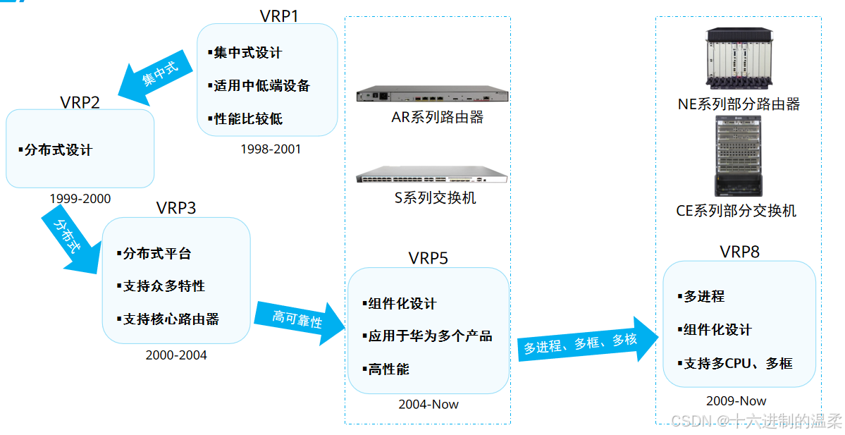
VRP发展
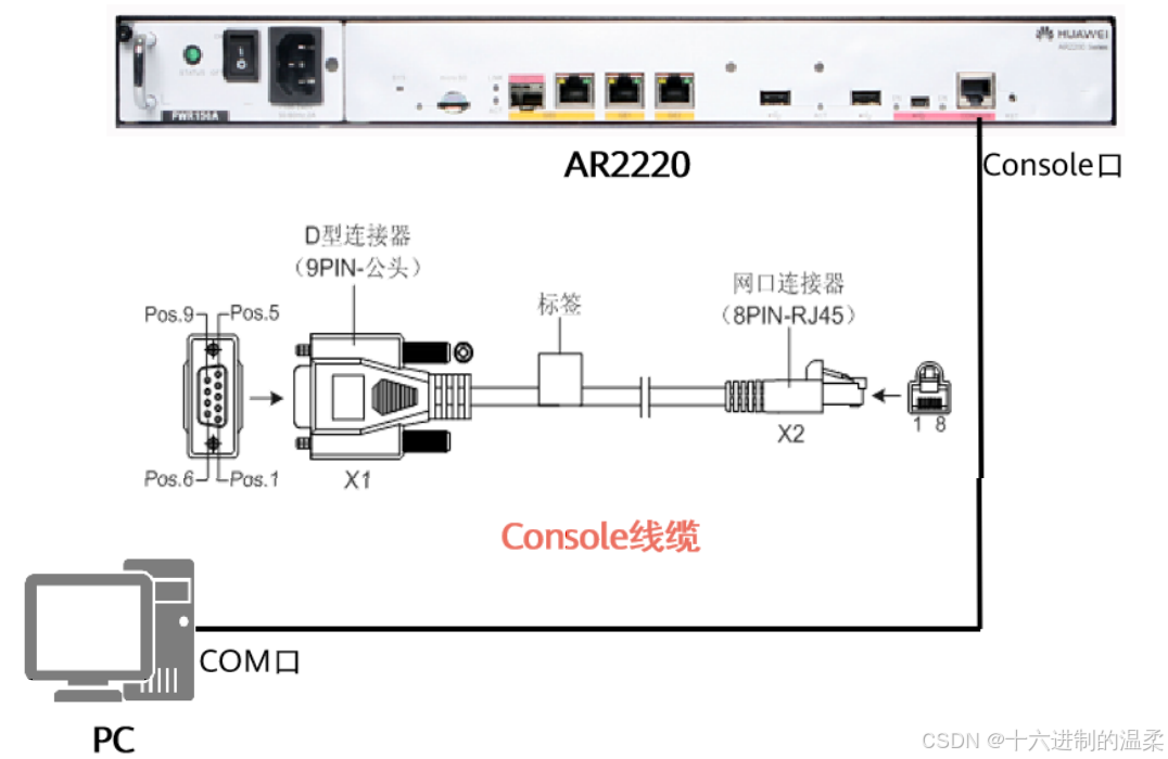
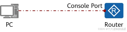
Console 界面
Console 用户界面用来管理和监控通过Console口登录的用户。
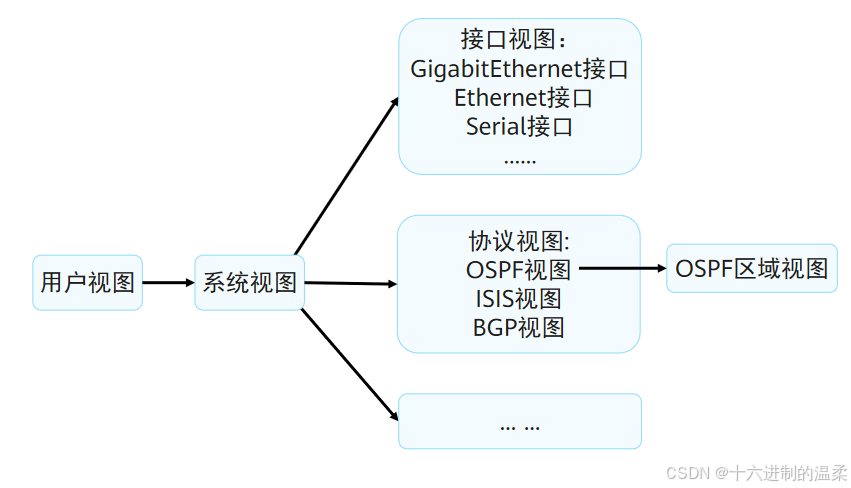
命令行视图
设备提供了多样的配置和查询命令,为便于用户使用这些命令,VRP系统按功能分类将命令分别
注册在不同的命令行视图下。
VRP常用命令
以下为VRP基础配置示例:
# 进入系统视图
system-view

# 配置接口IP地址
interface GigabitEthernet 0/0/1
 ip address 192.168.1.1 255.255.255.0

# 保存配置
save
示例:
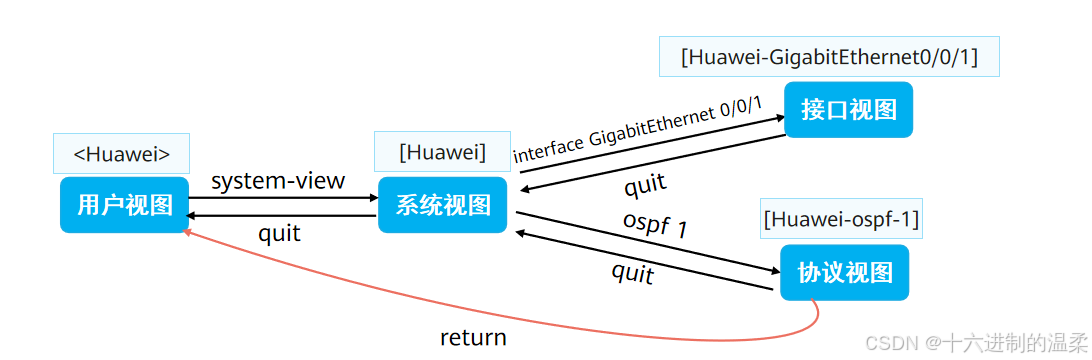
# 首先进入用户视图
<Huawei>
# 从用户视图进入系统视图
<Huawei> system-view
[Huawei]
# 从系统视图进入接口视图
[Huawei]interface GigabitEthernet 0/0/1
[Huawei-GigabitEthernet0/0/1]
# 配置IP地址
[Huawei-GigabitEthernet0/0/1]ip address 192.168.1.1 24
# 退回到系统视图
[Huawei-GigabitEthernet0/0/1]quit
[Huawei]
# 从系统视图进入协议视图
[Huawei]ospf 1
[Huawei-ospf-1]
# 从协议视图进入 OSPF 区域视图
[Huawei-ospf-1]area 0
[Huawei-ospf-1-area-0.0.0.0]
# 直接返回用户视图
[Huawei-ospf-1-area-0.0.0.0]return
<Huawei>
undo 命令行
在命令前加undo关键字,即为undo命令行。undo命令行一般用来恢复缺省情况、禁用某个功能
或者删除某项配置。
以下为参考案例:
# 使用undo命令行恢复缺省情况
<Huawei>system-view
[Huawei]sysname Server
[Server]undo sysname
[Huawei]
# 使用undo命令禁用某个功能
<Huawei>system-view
[Huawei]ftp server enable
[Huawei]undo ftp server
# 使用undo命令删除某项设置
[Huawei]interface g0/0/1
[Huawei-GigabitEthernet0/0/1]ip address 192.168.1.1 24
[Huawei-GigabitEthernet0/0/1]undo ip address
华为 VRP 系统基本操作
实验介绍
本实验通过配置华为设备,了解并熟悉华为VRP系统的基本操作
路由器型号:通用路由器。
实验步骤
通过Console方式登录到Router的CLI.
查看设备基本信息
 <Huawei>display version
 Huawei Versatile Routing Platform Software
 VRP (R) software, Version 5.130 (AR2200 V200R003C00)
 Copyright (C) 2011-2012 HUAWEI TECH CO., LTD
 Huawei AR2220 Router uptime is 0 week, 0 day, 0 hour, 1 minute
 BKP 0 version information:
1. PCB      Version  : AR01BAK2A VER.NC
 2. If Supporting PoE : No
 3. Board    Type     : AR2220
 4. MPU Slot Quantity : 1
 5. LPU Slot Quantity : 6
 ........
完成设备基本配置
# 从用户视图进入系统视图
<Huawei>system-view
Enter system view, return user view with Ctrl+Z.
# 修改Router的名字为Datacom-Router
[Huawei]sysname Datacom-Router
# 进入接口配置接口的IP地址
[Datacom-Router]interface GigabitEthernet 0/0/1
[Datacom-Router-GigabitEthernet0/0/1]ip address 192.168.1.1 24
# 来查看当前视图的运行配置
[Datacom-Router-GigabitEthernet0/0/1]display this
[V200R003C00]
#
interface GigabitEthernet0/0/1
 ip address 192.168.1.1 255.255.255.0
#
return
# 返回到上一视图
[Datacom-Router-GigabitEthernet0/0/1]quit
# 取消接口配置
[Datacom-Router]interface GigabitEthernet 0/0/1
[Datacom-Router-GigabitEthernet0/0/1]undo ip address
[Datacom-Router-GigabitEthernet0/0/1]quit
# 重新配置接口
[Datacom-Router]interface GigabitEthernet 0/0/2
[Datacom-Router-GigabitEthernet0/0/2]ip address 192.168.1.1 24
[Datacom-Router-GigabitEthernet0/0/2]quit
# 查看设备当前配置
[Datacom-Router]display current-configuration
[V200R003C00]
#
 sysname Datacom-Router
#
 snmp-agent local-engineid 800007DB03000000000000
 snmp-agent
#
 clock timezone China-Standard-Time minus 08:00:00
#
portal local-server load portalpage.zip
#
drop illegal-mac alarm
#
 set cpu-usage threshold 80 restore 75
#
aaa
 authentication-scheme default
 authorization-scheme default
 accounting-scheme default
 domain default
 domain default_admin
 local-user admin password cipher %$%$K8m.Nt84DZ}e#<0`8bmE3Uw}%$%$
 local-user admin service-type http
#
firewall zone Local
 priority 15
#
interface GigabitEthernet0/0/0
#
interface GigabitEthernet0/0/1
#
interface GigabitEthernet0/0/2
 ip address 192.168.1.1 255.255.255.0
#
interface NULL0
#
user-interface con 0
 authentication-mode password
user-interface vty 0 4
user-interface vty 16 20
#
wlan ac
#
return
保存设备当前配置
# 返回到用户视图
[Datacom-Router]quit
# 保存配置
<Datacom-Router>save
  The current configuration will be written to the device.
  Are you sure to continue? (y/n)[n]:`y`
  It will take several minutes to save configuration file, please
wait.......
  Configuration file had been saved successfully
  Note: The configuration file will take effect after being activated
# 比较当前配置与下一次启动所使用的配置
<Datacom-Router>compare configuration
The current configuration is the same as the next startup
configuration file.
 <Datacom-Router>
三、构建互联互通的 IP 网络
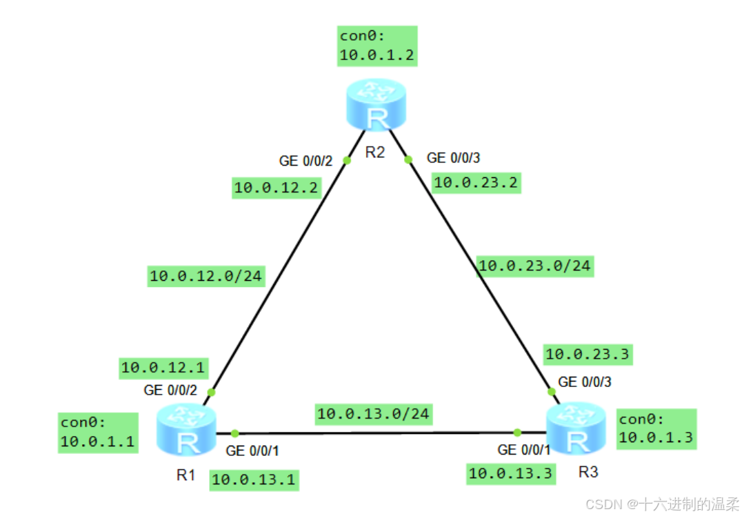
实验:IPv4 编址及 IPv4 路由基础
实验介绍
本实验将通过IPv4地址以及IPv4静态路由的配置,帮助学员理解路由转发的基本原理。
路由器型号:通用路由器
设备名称配置
#进入视图界面
<huawei>sys
#取消提示
[huawei]undo info-center enable
#改名称
<huawei>sysname R1
[R1]
查看路由器接口 IP 配置与路由表
以R1为例
# 查看路由器接口 IP 配置
[R1]display ip interface br
*down: administratively down
!down: FIB overload down
^down: standby
(l): loopback
(s): spoofing
(d): Dampening Suppressed
The number of interface that is UP in Physical is 3
The number of interface that is DOWN in Physical is 8
.......
# 查看路由器路由表
[R1]display ip routing-table
Route Flags: R - relay, D - download to fib
-----------------------------------------------------------------------
-------
Routing Tables: Public
         Destinations : 2       Routes : 2
Destination/Mask   Proto   Pre Cost     Flags NextHop
Interface
      127.0.0.0/8   Direct  0    0           D   127.0.0.1
InLoopBack0
      127.0.0.1/32 Direct  0    0           D   127.0.0.1
 InLoopBack0
配置路由接口 IP 地址
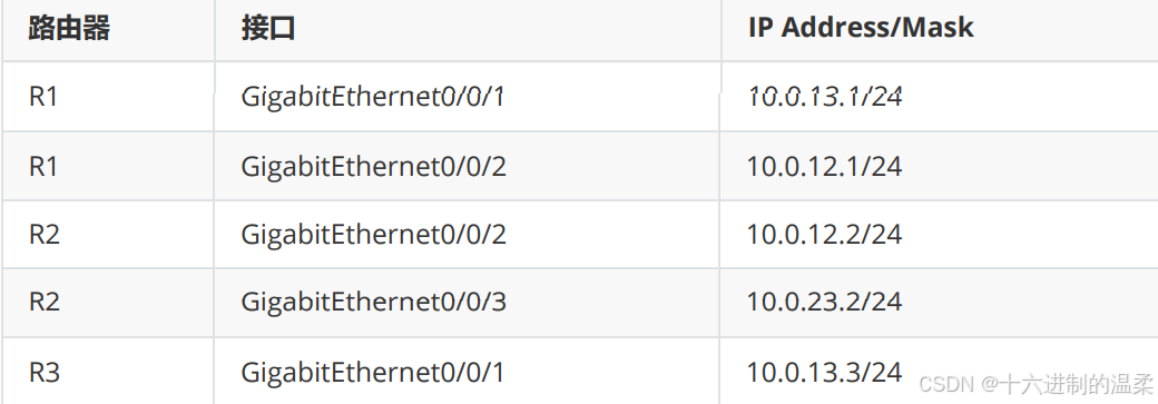

# R1 配置
[R1]interface GigabitEthernet 0/0/1
[R1-GigabitEthernet0/0/1]ip address 10.0.13.1 24
[R1-GigabitEthernet0/0/1]quit
[R1]interface GigabitEthernet 0/0/2
[R1-GigabitEthernet0/0/2]ip address 10.0.12.1 24
[R1-GigabitEthernet0/0/2]quit
# R2 配置
[R2]interface GigabitEthernet0/0/2
[R2-GigabitEthernet0/0/2]ip address 10.0.12.2 24
[R2-GigabitEthernet0/0/2]quit
[R2]interface GigabitEthernet0/0/3
[R2-GigabitEthernet0/0/3]ip address 10.0.23.2 24
[R2-GigabitEthernet0/0/3]quit
# R3 配置
[R3]interface GigabitEthernet0/0/1
[R3-GigabitEthernet0/0/1]ip address 10.0.13.3 24
[R3-GigabitEthernet0/0/1]quit
[R3]interface GigabitEthernet0/0/3
[R3-GigabitEthernet0/0/3]ip address 10.0.23.3 24
[R3-GigabitEthernet0/0/3]quit
# 使用 ping 工具测试联通性
[R1]ping -c 2 10.0.12.2
 PING 10.0.12.2: 56 data bytes, press CTRL_C to break
   Reply from 10.0.12.2: bytes=56 Sequence=1 ttl=255 time=40 ms
   Reply from 10.0.12.2: bytes=56 Sequence=2 ttl=255 time=60 ms
  --- 10.0.12.2 ping statistics ---
    2 packet(s) transmitted
    2 packet(s) received
    0.00% packet loss
   round-trip min/avg/max = 40/50/60 ms
[R1]ping -c 2 10.0.13.3
 PING 10.0.13.3: 56 data bytes, press CTRL_C to break
   Reply from 10.0.13.3: bytes=56 Sequence=1 ttl=255 time=30 ms
   Reply from 10.0.13.3: bytes=56 Sequence=2 ttl=255 time=30 ms
  --- 10.0.13.3 ping statistics ---
    2 packet(s) transmitted
    2 packet(s) received
    0.00% packet loss
   round-trip min/avg/max = 30/30/30 ms
#查看R1的路由表
[R1]display ip routing-table
Route Flags: R - relay, D - download to fib
-----------------------------------------------------------------------
-------
Routing Tables: Public
         Destinations : 6       Routes : 6
Destination/Mask   Proto   Pre Cost     Flags NextHop
Interface
      10.0.12.0/24 Direct  0    0           D   10.0.12.1
GigabitEthernet
0/0/2
      10.0.12.1/32 Direct  0    0           D   127.0.0.1
GigabitEthernet
0/0/2
      10.0.13.0/24 Direct  0    0           D   10.0.13.1
GigabitEthernet
0/0/1
      10.0.13.1/32 Direct  0    0           D   127.0.0.1
GigabitEthernet
0/0/1
      127.0.0.0/8   Direct  0    0           D   127.0.0.1
InLoopBack0
      127.0.0.1/32 Direct  0    0           D   127.0.0.1
InLoopBack0
可以看到,在接口IP地址配置完成之后,针对每个接口自动生成了二条直连路由。分别是:
- 指向接口所在网段的路由。
- 指向接口IP地址的主机路由。
注:主机路由就是掩码长度为32的路由。
配置 LoopBack 接口
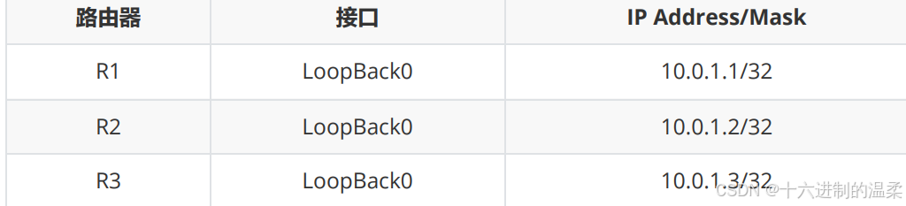
# R1 配置
[R1]interface LoopBack 0
[R1-LoopBack0]ip address 10.0.1.1 32
[R1-LoopBack0]quit
# R2 配置
[R2]interface LoopBack 0
[R2-LoopBack0]ip address 10.0.1.2 32
[R2-LoopBack0]quit
# R3 配置
[R3]interface LoopBack 0
[R3-LoopBack0]ip address 10.0.1.3 32
[R3-LoopBack0]quit
# 查看设备上的路由表,以R1为例
[R1]display ip routing-table
Route Flags: R - relay, D - download to fib
-----------------------------------------------------------------------
-------
Routing Tables: Public
         Destinations : 7       Routes : 7
Destination/Mask   Proto   Pre Cost     Flags NextHop
Interface
       10.0.1.1/32 Direct  0    0           D   127.0.0.1
LoopBack0
      10.0.12.0/24 Direct  0    0           D   10.0.12.1
GigabitEthernet
0/0/2
      10.0.12.1/32 Direct  0    0           D   127.0.0.1
GigabitEthernet
0/0/2
      10.0.13.0/24 Direct  0    0           D   10.0.13.1
GigabitEthernet
0/0/1
      10.0.13.1/32 Direct  0    0           D   127.0.0.1
GigabitEthernet
0/0/1
      127.0.0.0/8   Direct  0    0           D   127.0.0.1
InLoopBack0
.........
结果表明:增加一条回环口直连路由
测试各 LoopBack 接口之间的联通性
[R1]ping -c 2 -a 10.0.1.1 10.0.1.2
 PING 10.0.1.2: 56 data bytes, press CTRL_C to break
   Request time out
   Request time out
  --- 10.0.1.2 ping statistics ---
    2 packet(s) transmitted
    0 packet(s) received
    100.00% packet loss
此时由于路由器上没有到底该目的IP的路由条目,所以无法PING通
配置静态路由
# 在 R1 上配置到达 R2 和 R3 的 LoopBack0 接口的路由条目
[R1]ip route-static 10.0.1.2 32 10.0.12.2
[R1]ip route-static 10.0.1.3 32 10.0.13.3
# 再次查看路由表
[R1]display ip routing-table
Route Flags: R - relay, D - download to fib
-----------------------------------------------------------------------
-------
Routing Tables: Public
         Destinations : 9       Routes : 9
Destination/Mask   Proto   Pre Cost     Flags NextHop
Interface
       10.0.1.1/32 Direct  0    0           D   127.0.0.1
LoopBack0
       10.0.1.2/32 Static  60   0         RD   10.0.12.2
GigabitEthernet
0/0/2
       10.0.1.3/32 Static  60   0         RD   10.0.13.3
GigabitEthernet
0/0/1
      10.0.12.0/24 Direct  0    0           D   10.0.12.1
GigabitEthernet
0/0/2
.......
配置的静态路由被加入到了IP路由表中。
再次测试各 LoopBack 接口之间的联通性
[R1]ping -a 10.0.1.1 10.0.1.2
 PING 10.0.1.2: 56 data bytes, press CTRL_C to break
   Request time out
   Request time out
   Request time out
   Request time out
   Request time out
  --- 10.0.1.2 ping statistics ---
    5 packet(s) transmitted
    0 packet(s) received
    100.00% packet loss
还是无法 PING 通 R2 的 LoopBack0 接口,因为此时 R2 上没有到 R1 的 LoopBack0 的路由。
如果使用以下命令,则可以 PING 通 10.0.1.2
[R1]ping 10.0.1.2
 PING 10.0.1.2: 56 data bytes, press CTRL_C to break
   Reply from 10.0.1.2: bytes=56 Sequence=1 ttl=255 time=50 ms
   Reply from 10.0.1.2: bytes=56 Sequence=2 ttl=255 time=40 ms
   Reply from 10.0.1.2: bytes=56 Sequence=3 ttl=255 time=20 ms
   Reply from 10.0.1.2: bytes=56 Sequence=4 ttl=255 time=40 ms
   Reply from 10.0.1.2: bytes=56 Sequence=5 ttl=255 time=30 ms
  --- 10.0.1.2 ping statistics ---
    5 packet(s) transmitted
    5 packet(s) received
    0.00% packet loss
   round-trip min/avg/max = 20/36/50 ms
因为 ping 默认使用物理端口测试,也就是GigabitEthernet 0/0/2 (10.0.12.1) 接口,而目标路由器跟10.0.12.1所在接口是在直连的同一网段
在 R2 上添加到达 R1 的 LoopBack0 的路由,,并再次测试,此时可以 PING 通 R2
[R2]ip route-static 10.0.1.1 32 10.0.12.1
[R1]ping -a 10.0.1.1 10.0.1.2
 PING 10.0.1.2: 56 data bytes, press CTRL_C to break
   Reply from 10.0.1.2: bytes=56 Sequence=1 ttl=255 time=30 ms
   Reply from 10.0.1.2: bytes=56 Sequence=2 ttl=255 time=20 ms
   Reply from 10.0.1.2: bytes=56 Sequence=3 ttl=255 time=40 ms
   Reply from 10.0.1.2: bytes=56 Sequence=4 ttl=255 time=10 ms
   Reply from 10.0.1.2: bytes=56 Sequence=5 ttl=255 time=30 ms
  --- 10.0.1.2 ping statistics ---
    5 packet(s) transmitted
    5 packet(s) received
    0.00% packet loss
   round-trip min/avg/max = 10/26/40 ms
完成剩余的路由配置
# 在 R2 上配置到达 R1 和 R3 的 LoopBack0 接口的路由条目
[R2]ip route-static 10.0.1.3 32 10.0.23.3
# 在 R3 上配置到达 R1 和 R2 的 LoopBack0 接口的路由条目
[R3]ip route-static 10.0.1.1 32 10.0.13.1
[R3]ip route-static 10.0.1.2 32 10.0.23.2
配置备份路径
配置R1->R3->R2作为R1的LoopBack0到R2的LoopBack0接口的备份路径。
# R1 去的路由
[R1]ip route-static 10.0.1.2 32 10.0.13.3 preference 100
# 查看 R1 路由表
[R1]ip route-static 10.0.1.2 32 10.0.13.3 preference 100
[R1]display ip routing-table
Route Flags: R - relay, D - download to fib
-----------------------------------------------------------------------
-------
Routing Tables: Public
         Destinations : 9       Routes : 9
  ......
# R2 回的路由
[R2]ip route-static 10.0.1.1 32 10.0.23.3 preference 100
# 查看 R2 路由表
[R2]ip route-static 10.0.1.1 32 10.0.23.3 preference 100
[R2]display ip routing-table
Route Flags: R - relay, D - download to fib
-----------------------------------------------------------------------
-------
Routing Tables: Public
         Destinations : 9       Routes : 9
Destination/Mask   Proto   Pre Cost     Flags NextHop
Interface
       10.0.1.1/32 Static  60   0         RD   10.0.12.1
       .......
此时配置的 preference 为 100 的静态路由没有被加载到路由表中。
关闭 R1 和 R2 之间的链路对应的接口(GigabitEthernet0/0/2),使得优先级高的路由失效
[R1]interface GigabitEthernet0/0/2
[R1-GigabitEthernet0/0/2]shutdown
[R1-GigabitEthernet0/0/2]quit
# R1 路由表
[R1]display ip routing-table
Route Flags: R - relay, D - download to fib
-----------------------------------------------------------------------
-------
Routing Tables: Public
         Destinations : 7       Routes : 7
         ......
# R2 路由表
[R2]display ip routing-table
Route Flags: R - relay, D - download to fib
-----------------------------------------------------------------------
-------
Routing Tables: Public
         Destinations : 7       Routes : 7
Destination/Mask   Proto   Pre Cost     Flags NextHop
......
此时由于链路断开,原先的静态路由失效,低优先级的静态路由被激活。
检查联通性
[R1]ping -a 10.0.1.1 10.0.1.2
 PING 10.0.1.2: 56 data bytes, press CTRL_C to break
   Reply from 10.0.1.2: bytes=56 Sequence=1 ttl=254 time=90 ms
   Reply from 10.0.1.2: bytes=56 Sequence=2 ttl=254 time=10 ms
   Reply from 10.0.1.2: bytes=56 Sequence=3 ttl=254 time=70 ms
   Reply from 10.0.1.2: bytes=56 Sequence=4 ttl=254 time=50 ms
   Reply from 10.0.1.2: bytes=56 Sequence=5 ttl=254 time=30 ms
  --- 10.0.1.2 ping statistics ---
    5 packet(s) transmitted
    5 packet(s) received
    0.00% packet loss
   round-trip min/avg/max = 10/50/90 ms
 # 追踪数据包路径
[R1]tracert -a 10.0.1.1 10.0.1.2
 traceroute to  10.0.1.2(10.0.1.2), max hops: 30 ,packet length:
40,press CTRL_C
 to break
 1 10.0.13.3 10 ms  50 ms  40 ms
 2 10.0.23.2 80 ms  70 ms  60 ms
配置默认路由
通过默认路由实现R1的LoopBack0接口和R2的LoopBack0接口互联互通。
# 恢复接口并删除已经配置的路由条目
[R1]interface GigabitEthernet 0/0/2
[R1-GigabitEthernet0/0/2]undo shutdown
[R1-GigabitEthernet0/0/2]quit
[R1]undo ip route-static 10.0.1.2 255.255.255.255 10.0.12.2
[R1]undo ip route-static 10.0.1.2 255.255.255.255 10.0.13.3 preference
100
# 查看 R1 路由表
[R1]display ip routing-table
Route Flags: R - relay, D - download to fib
-----------------------------------------------------------------------
-------
Routing Tables: Public
         Destinations : 8       Routes : 8
         .......
在 R1 上配置默认路由
[R1]ip route-static 0.0.0.0 0 10.0.12.2
[R1]display ip routing-table
Route Flags: R - relay, D - download to fib
-----------------------------------------------------------------------
-------
Routing Tables: Public
         Destinations : 9       Routes : 9
Destination/Mask   Proto   Pre Cost     Flags NextHo
.....
测试 R1 的 LoopBack0 接口到 R2 的 LoopBack0 接口的联通性
[R1]ping -a 10.0.1.1 10.0.1.2
 PING 10.0.1.2: 56 data bytes, press CTRL_C to break
   Reply from 10.0.1.2: bytes=56 Sequence=1 ttl=255 time=30 ms
   Reply from 10.0.1.2: bytes=56 Sequence=2 ttl=255 time=30 ms
   Reply from 10.0.1.2: bytes=56 Sequence=3 ttl=255 time=10 ms
   Reply from 10.0.1.2: bytes=56 Sequence=4 ttl=255 time=30 ms
   Reply from 10.0.1.2: bytes=56 Sequence=5 ttl=255 time=20 ms
  --- 10.0.1.2 ping statistics ---
    5 packet(s) transmitted
    5 packet(s) received
    0.00% packet loss
   round-trip min/avg/max = 10/24/30 ms
此时 R1 的 LoopBack0 接口到 R2 的 LoopBack0 接口之间可以互联互通
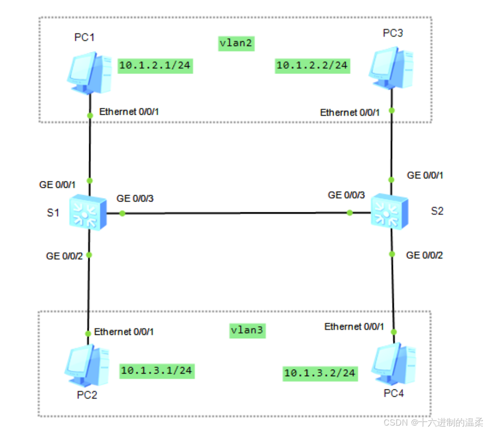
四、构建以太网交换网络
实验介绍
本实验通过配置华为交换机设备,了解并熟悉VLAN技术的相关配置
实验步骤
设备基础配置
- 配置 4 台 PC IP地址
- 配置交换机名称
access 口配置
# 配置接口类型和所属vlan
[S1]interface GigabitEthernet 0/0/1
[S1-GigabitEthernet0/0/1]port link-type access
[S1-GigabitEthernet0/0/1]interface GigabitEthernet 0/0/2
[S1-GigabitEthernet0/0/2]port link-type access
[S1-GigabitEthernet0/0/2]quit
# 创建 vlan
[S1]vlan 2
# 将接口划分到 vlan
[S1-vlan2]port GigabitEthernet 0/0/1
[S1-vlan2]vlan 3
[S1-vlan3]port GigabitEthernet 0/0/2
# 批量创建 vlan
[S2]vlan batch 2 to 3
# 在接口视图中,指定所属 vlan
[S2]interface GigabitEthernet 0/0/1
[S2-GigabitEthernet0/0/1]port link-type access
[S2-GigabitEthernet0/0/1]port default vlan 2
[S2-GigabitEthernet0/0/1]interface GigabitEthernet 0/0/2
[S2-GigabitEthernet0/0/2]port link-type access
[S2-GigabitEthernet0/0/2]port default vlan 3
trunk 口配置
# 配置S1
[S1]interface GigabitEthernet 0/0/3
# 配置接口类型为trunk
[S1-GigabitEthernet0/0/3]port link-type trunk
# 放行vlan 2和3,不放行vlan 1
[S1-GigabitEthernet0/0/3]port trunk allow-pass vlan 2 3
[S1-GigabitEthernet0/0/3]undo port trunk allow-pass vlan 1
# 配置S2
[S2]interface GigabitEthernet 0/0/3
[S2-GigabitEthernet0/0/3]port link-type trunk
[S2-GigabitEthernet0/0/3]port trunk allow-pass vlan 2 3
[S2-GigabitEthernet0/0/3]undo port trunk allow-pass vlan 1
测试
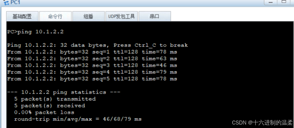
PC1可以 ping 通不同交换机上相同 vlan 的 PC3
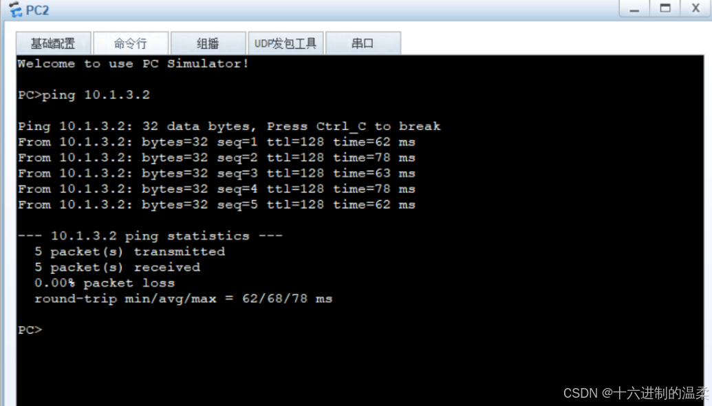
PC2 可以 ping 通不同交换机上相同 vlan 的 PC4


 520
520

 被折叠的 条评论
为什么被折叠?
被折叠的 条评论
为什么被折叠?
 到【灌水乐园】发言


