


目录
第一阶段是MSTP核心技术发展的初期,也是相应的第一个发展阶段。在技术发展的初期,MSTP核心技术主要的使用方式是与以太网进行数据点对点的传输过程中,并且相应的数据受到颗粒的限制,在传输的过程中具有一定的片面性。在第一代技术成型并且运用的过程中,其对于流量的控制和多个以太网的业务数据的传输当中不能起到作用。在传输的技术上具有一定的阻碍作用,这使得对于以太网的传输层保护无法实现。
第二阶段的发展通过改进和不断的完善,使得MSTP核心技术支持了以太网的二次交换。其由于科技的不断发展和完善,MSTP核心技术能够实现以太网用户和多个基于同步数字体系的虚荣点进行点对点的传输方式,实现了路径帧的交换。相对于第一代的技术,第二代的技术当中包含的更加全面。其能够实现网络控制以及多任务的用户的隔离手段。使得数据的传输过程中更加的全面,但是其同时存在一定的弊端,业务宽带的宽粒度依旧受到相应的限制,MSTP核心技术当中的VLAN功能也不能够适应大型城市的用网需求。
第三阶段的MSTP核心技术是近年来经过改善和发展得来的,其重要的特点是支持以太网的QoS,在第三个发展阶段,其中加入了智能化的技术手段,引入了成帧规程(GFP:Generic Framing Procedure)高速封装协议以及智能适配层以及调控机制进行相应的技术应用,使得MSTP核心技术的发展更加全面,对于网络用户的隔离以及接入控制都有一定的推动作用,并且能够确保在传输的过程中做到以太网保护层的安全性。除此之外,在第三代的MSTP技术的发展过程中还具有相当强的可扩展性,是发展最为全面的MSTP技术,并且能够为以太网的发展提供强有力的支持。
原理
MSTP是将传统的SDH复用器、数字交叉链接器(DXC)、WDM终端、网络二层交换机和lP边缘路由器等多个独立的设备集成为一个网络设备,即基于SDH技术的多业务传送平台(MSTP),进行统一控制和管理。基于SDH的MSTP技术最适合作为网络边缘的融合节点支持混合型业务,特别是以TDM业务为主的混合业务。以SDH为基础的多业务平台可以更有效地支持分组数据业务,有助于实现从电路交换网向分组网的过渡。
MSTP可以实现对多种业务的处理,包括PDH业务、SDH业务、ATM数据业务及IP、以太网业务等,既能实现快速传输,又能满足多业务承载,更重要的是能提供电信级的QoS能力。
功能
(1)具有TDM、以太网以及ATM网络等多样业务的接入服务。
(2)包括TDM、以太网以及ATM网络等多样业务的传输服务包括P2P的网络传送功能。
(3)支持以太网与ATM业务的网络处理与复用功能。
(4)支持以太网与ATM业务,映射到SDH虚拟容器的功能。
对于MSTP技术而言,主要采用传统的SDH虚拟容器、数字交叉DXCWDM数据终端,可以实现电路交换与分组网络的转变。与SDH相比,它能够承载更丰富多样的业务类型,能够实现多种业务类型的统一调配和处理。MSTP在SDH设施上增加了多种业务类型的插板,能够满足多种业务类型的接入需要。
1. 拓扑
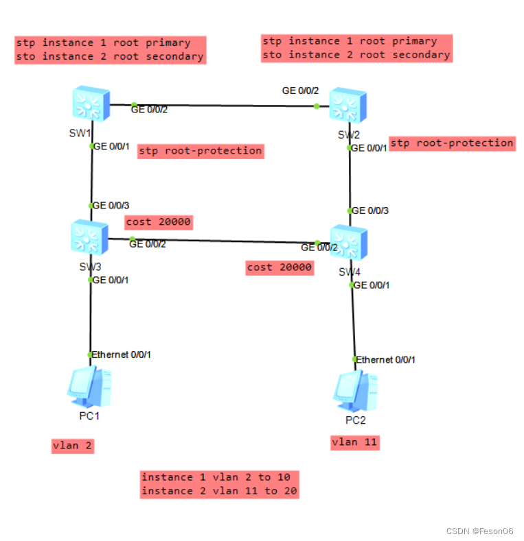
instance可以理解为树。如上图示,那么instance 1,就可以理解为树1,树1包含了vlan 2到vlan 10。树2(instance 2)包含了vlan 11到vlan 20。
2. 配置MSTP
当两台设备的 MST 域的域名、实例和 VLAN 的映射关系、MST 域的修订级别都相同时,这两台设备属于同一个 MST 域。 不能将同一个 VLAN 映射到多个不同的实例上。如果将一个已经和实例建立映射关系的 VLAN 又映射到另一个实例 上,原来的映射关系将被取消。
# 在 DeviceA 上配置 MST 域。MST域=Multiple Spanning Tree Region
<HUAWEI> system-view [HUAWEI] sysname DeviceA [DeviceA] stp region-configuration
[DeviceA-mst-region]  region-name  RG1
[DeviceA-mst-region] instance 1 vlan 2 to 10
[DeviceA-mst-region] instance 2 vlan 11 to 20
[DeviceA-mst-region] quit
# 在 DeviceB 上配置 MST 域。
<HUAWEI> system-view [HUAWEI] sysname DeviceB [DeviceB] stp region-configuration
[DeviceB-mst-region]  region-name  RG1
[DeviceB-mst-region] instance 1 vlan 2 to 10
[DeviceB-mst-region] instance 2 vlan 11 to 20
[DeviceB-mst-region] quit
# 在 DeviceC 上配置 MST 域。
<HUAWEI> system-view [HUAWEI] sysname DeviceC [DeviceC] stp region-configuration
[DeviceC-mst-region]  region-name  RG1
[DeviceC-mst-region] instance 1 vlan 2 to 10
[DeviceC-mst-region] instance 2 vlan 11 to 20
[DeviceC-mst-region] quit
# 在 DeviceD 上配置 MST 域。
<HUAWEI> system-view
[HUAWEI] sysname DeviceD
[DeviceD] stp region-configuration
[DeviceD-mst-region] region-name RG1
[DeviceD-mst-region] instance 1 vlan 2 to 10
[DeviceD-mst-region] instance 2 vlan 11 to 20
[DeviceD-mst-region] quit
2. 在 MST 域 RG1 内,分别配置 MSTI1、MSTI2 的根桥和备份根桥。
MSTI=Multiple Spanning Tree Instance
# 配置 DeviceA 为 MSTI1 的根桥。
[DeviceA] stp instance 1 root primary
# 配置 DeviceB 为 MSTI1 的备份根桥。
[DeviceB] stp instance 1 root secondary
# 配置 DeviceB 为 MSTI2 的根桥。
[DeviceB] stp instance 2 root primary
# 配置 DeviceA 为 MSTI2 的备份根桥。
[DeviceA] stp instance 2 root secondary
3. 配置同一网络内所有设备的端口路径开销应使用相同的计算方法;配置实例 MSTI1 和 MSTI2 中将要被阻塞端口的路径开销值大于缺省值。
# 配置 DeviceA 的端口路径开销计算方法为华为计算方法。
[DeviceA] stp pathcost-standard legacy
# 配置 DeviceB 的端口路径开销计算方法为华为计算方法。
[DeviceB] stp pathcost-standard legacy
# 配置 DeviceC 的端口路径开销计算方法为华为计算方法,将端口 10GE1/0/2 在实例 MSTI2 中的路 径开销值配置为 20000。
[DeviceC] stp pathcost-standard legacy
[DeviceC] interface 10ge 1/0/2
[DeviceC-10GE1/0/2] portswitch
[DeviceC-10GE1/0/2] stp instance 2 cost 20000
[DeviceC-10GE1/0/2] quit
# 配置 DeviceD 的端口路径开销计算方法为华为计算方法,将端口 10GE1/0/2 在实例 MSTI1 中的路径 开销值配置为 20000。
[DeviceD] stp pathcost-standard legacy
[DeviceD] interface 10ge 1/0/2
[DeviceD-10GE1/0/2] portswitch
[DeviceD-10GE1/0/2] stp instance 1 cost 20000
[DeviceD-10GE1/0/2] quit
4. 设备全局启用 MSTP。 缺省情况下,设备上生成树协议处于使能状态,无需操作。在系统视图下执行命令 stp enable 可以启用 MSTP 功能。
5. 在设备与终端相连的端口上去使能 MSTP。
# 在 DeviceC 端口 10GE1/0/1 上去使能 MSTP 功能。
[DeviceC] interface 10ge 1/0/1
[DeviceC-10GE1/0/1] portswitch
[DeviceC-10GE1/0/1] stp disable
[DeviceC-10GE1/0/1] quit
# 在 DeviceD 端口 10GE1/0/1 上去使能 MSTP 功能。
[DeviceD] interface 10ge 1/0/1
[DeviceD-10GE1/0/1] portswitch
[DeviceD-10GE1/0/1] stp disable
[DeviceD-10GE1/0/1] quit
6. 配置保护功能,如在各实例的根桥设备的指定端口配置根保护功能。 # 在 DeviceA 端口 10GE1/0/1 上启动根保护。
[DeviceA] interface 10ge 1/0/1
[DeviceA-10GE1/0/1] portswitch
[DeviceA-10GE1/0/1]  stp root-protection
[DeviceA-10GE1/0/1] quit
# 在 DeviceB 端口 10GE1/0/1 上启动根保护。
[DeviceB] interface 10ge 1/0/1
[DeviceB-10GE1/0/1] portswitch
[DeviceB-10GE1/0/1]  stp root-protection
[DeviceB-10GE1/0/1] quit
7. 创建 VLAN 并将接口加入 VLAN。 # 在 DeviceA 上创建 VLAN2~20,并将 DeviceA 的端口 10GE1/0/1 和 10GE1/0/2 分别加入 VLAN。
[DeviceA] vlan batch 2 to 20 [DeviceA] interface 10ge 1/0/1 [DeviceA-10GE1/0/1] portswitch
[DeviceA-10GE1/0/1] port link-type trunk
[DeviceA-10GE1/0/1] port trunk allow-pass vlan 2 to 20
[DeviceA-10GE1/0/1] quit [DeviceA] interface 10ge 1/0/2 [DeviceA-10GE1/0/2] portswitch
[DeviceA-10GE1/0/2] port link-type trunk
[DeviceA-10GE1/0/2] port trunk allow-pass vlan 2 to 20
[DeviceA-10GE1/0/2] quit
# 在 DeviceB 上创建 VLAN2~20,并将 DeviceB 的端口 10GE1/0/1 和 10GE1/0/2 分别加入 VLAN。
[DeviceB] vlan batch 2 to 20 [DeviceB] interface 10ge 1/0/1 [DeviceB-10GE1/0/1] portswitch
[DeviceB-10GE1/0/1] port link-type trunk
[DeviceB-10GE1/0/1] port trunk allow-pass vlan 2 to 20
[DeviceB-10GE1/0/1] quit [DeviceB] interface 10ge 1/0/2 [DeviceB-10GE1/0/2] portswitch
[DeviceB-10GE1/0/2] port link-type trunk
[DeviceB-10GE1/0/2] port trunk allow-pass vlan 2 to 20
[DeviceB-10GE1/0/2] quit
# 在 DeviceC 上创建 VLAN2~20,并将 DeviceC 的端口 10GE1/0/1、10GE1/0/2 和 10GE1/0/3 分 别加入 VLAN。
[DeviceC] vlan batch 2 to 20 [DeviceC] interface 10ge 1/0/1 [DeviceC-10GE1/0/1] portswitch
[DeviceC-10GE1/0/1] port link-type access [DeviceC-10GE1/0/1] port default vlan 2 [DeviceC-10GE1/0/1] quit
[DeviceC] interface 10ge 1/0/2
[DeviceC-10GE1/0/2] portswitch
[DeviceC-10GE1/0/2] port link-type trunk
[DeviceC-10GE1/0/2] port trunk allow-pass vlan 2 to 20
[DeviceC-10GE1/0/2] quit [DeviceC] interface 10ge 1/0/3 [DeviceC-10GE1/0/3] portswitch
[DeviceC-10GE1/0/3] port link-type trunk
[DeviceC-10GE1/0/3] port trunk allow-pass vlan 2 to 20
[DeviceC-10GE1/0/3] quit
# 在 DeviceD 上创建 VLAN2~20,并将 DeviceD 的端口 10GE1/0/1、10GE1/0/2 和 10GE1/0/3 分 别加入 VLAN。
[DeviceD] vlan batch 2 to 20 [DeviceD] interface 10ge 1/0/1 [DeviceD-10GE1/0/1] portswitch
[DeviceD-10GE1/0/1] port link-type access [DeviceD-10GE1/0/1] port default vlan 11 [DeviceD-10GE1/0/1] quit
[DeviceD] interface 10ge 1/0/2
[DeviceD-10GE1/0/2] portswitch
[DeviceD-10GE1/0/2] port link-type trunk
[DeviceD-10GE1/0/2] port trunk allow-pass vlan 2 to 20
[DeviceD-10GE1/0/2] quit [DeviceD] interface 10ge 1/0/3 [DeviceD-10GE1/0/3] portswitch
[DeviceD-10GE1/0/3] port link-type trunk
[DeviceD-10GE1/0/3] port trunk allow-pass vlan 2 to 20
[DeviceD-10GE1/0/3] quit
3. 配置脚本
MSTP配置脚本-同一个域下
SW_A
system-view
sysname SW_A
undo info-center enable

vlan batch 2 to 20

stp instance 1 root primary
stp instance 2 root secondary
stp pathcost-standard legacy

stp mode mstp
stp region-configuration
region-name RG1
revision-level 1
instance 1 vlan 2 to 10
instance 2 vlan 11 to 20
active region-configuration
quit

interface GigabitEthernet 0/0/1
port link-type trunk
port trunk allow-pass vlan 2 to 20
stp root-protection

interface GigabitEthernet 0/0/2
port link-type trunk
port trunk allow-pass vlan 2 to 20
stp root-protection
quit

quit
save
SW_B
system-view
sysname SW_B
undo info-center enable

vlan batch 2 to 20

stp instance 1 root secondary
stp instance 2 root primary
stp pathcost-standard legacy

stp mode mstp
stp region-configuration
region-name RG1
revision-level 1
instance 1 vlan 2 to 10
instance 2 vlan 11 to 20
active region-configuration
quit

interface GigabitEthernet 0/0/1
port link-type trunk
port trunk allow-pass vlan 2 to 20
stp root-protection

interface GigabitEthernet 0/0/2
port link-type trunk
port trunk allow-pass vlan 2 to 20
stp root-protection
quit

quit
save
y
SW_C
system-view
sysname SW_C
undo info-center enable

vlan batch 2 to 20

stp pathcost-standard legacy

stp mode mstp
stp region-configuration
region-name RG1
revision-level 1
instance 1 vlan 2 to 10
instance 2 vlan 11 to 20
active region-configuration
quit

interface GigabitEthernet 0/0/2
port link-type trunk
port trunk allow-pass vlan 2 to 20
stp instance 2 cost 20000

interface GigabitEthernet 0/0/3
port link-type trunk
port trunk allow-pass vlan 2 to 20

interface GigabitEthernet 0/0/1
port link-type access
port default vlan 2
stp disable
quit

quit
save
y
SW_D
system-view
sysname SW_D
undo info-center enable

vlan batch 2 to 20

stp pathcost-standard legacy

stp mode mstp
stp region-configuration
region-name RG1
revision-level 1
instance 1 vlan 2 to 10
instance 2 vlan 11 to 20
active region-configuration
quit

interface GigabitEthernet 0/0/2
port link-type trunk
port trunk allow-pass vlan 2 to 20
stp instance 2 cost 20000

interface GigabitEthernet 0/0/3
port link-type trunk
port trunk allow-pass vlan 2 to 20

interface GigabitEthernet 0/0/1
port link-type access
port default vlan 11
stp disable
quit

quit
save
y
4. 验证MSTP配置
检查配置结果 在网络计算稳定后,执行以下操作,验证配置结果。本配置举例以实例 1 和实例 2 为例,因此不用关注实例 0中端口的状态。
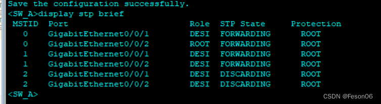
# 在 SW_A 上执行命令 display stp brief,查看端口角色和端口状态。
在 MSTI1 中,由于 SW_A 是根 桥,SW_A 的端口 GE0/0/2 和 GE0/0/1 成为指定端口。在 MSTI2 中,SW_A 的端口 GE0/0/1 成为指定端口,端口 GE0/0/2 成为根端口。
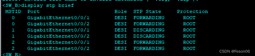
# 在 SW_B 上执行命令 display stp brief,查看端口角色和端口状态。
在 MSTI2 中,由于 SW_B是根桥,端口GE0/0/1和GE0/0/2在MSTI2中成为指定端口。
在MSTI1中,SW_B的端口 GE0/0/1 成为指定端口,端口 GE0/0/2 成为根端口。
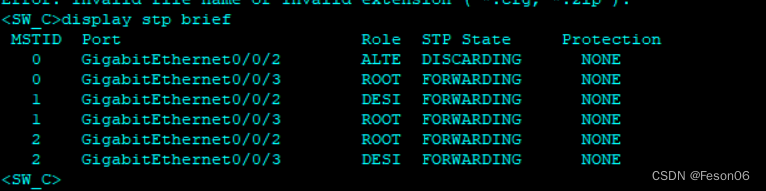
# 在 SW_C 上执行命令 display stp interface brief,查看端口角色和端口状态。
SW_C 的端口 GE0/0/3 在 MSTI1 和 MSTI2 中为根端口。SW_C 的另一个端口 GE0/0/2,在 MSTI2 中被阻塞, 在 MSTI1 中被计算为指定端口。
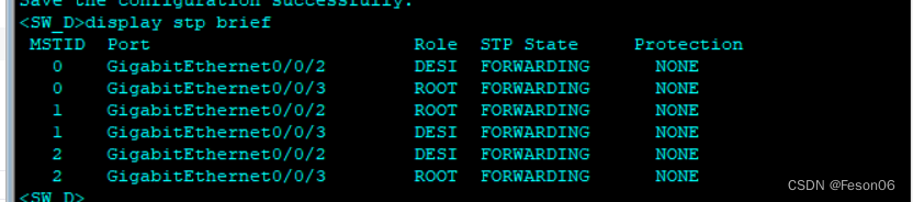
# 在 SW_D 上执行命令 display stp interface brief,查看端口角色和端口状态。
SW_D 的端口 GE0/0/3 在 MSTI1 和 MSTI2 中为根端口。SW_D 的另一个端口 GE0/0/2,在 MSTI1 中被阻塞,在 MSTI2 中被计算为指定端口。


 1639
1639


 被折叠的 条评论
为什么被折叠?
被折叠的 条评论
为什么被折叠?
 到【灌水乐园】发言


