


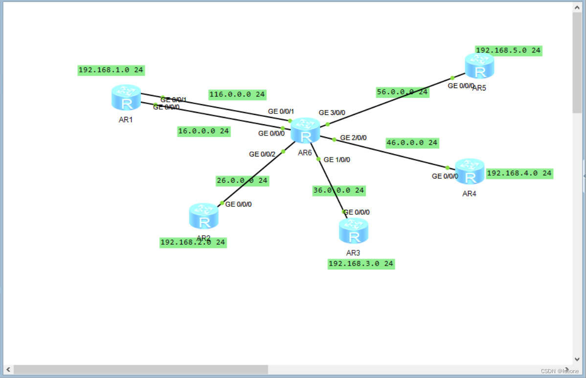
按照如图所示配置ip,在向r1到r5向r6配置一条缺省路由(r1为例)
[r1]ip route-static 0.0.0.0 0 16.0.0.2
[r1]ip route-static 0.0.0.0 0 116.0.0.2
建立在r1到r3上建立隧道接口并进行mgre的环境在打开ospf的伪广播(r1为例 r2为例)r1为中心站点
r1-Tunnel0/0/0]ip address 192.168.6.1 24
[r1-Tunnel0/0/0]tunnel-protocol gre p2mp
[r1-Tunnel0/0/0]source 16.0.0.1
[r1-Tunnel0/0/0]nhrp network-id 100


[r2-Tunnel0/0/0]ip address 192.168.6.2 255.255.255.0
 [r2-Tunnel0/0/0]tunnel-protocol gre p2mp
[r2-Tunnel0/0/0] source GigabitEthernet0/0/0
 [r2-Tunnel0/0/0]ospf dr-priority 0
 [r2-Tunnel0/0/0]nhrp network-id 100
[r2-Tunnel0/0/0] nhrp entry 192.168.6.1 16.0.0.1 register
r1 r4 r5互为中心结构与分支(r1为例)
r1为中心的配置
r1-Tunnel0/0/1]ip address 192.168.7.1 24
[r1-Tunnel0/0/1]tunnel-protocol gre p2mp
[r1-Tunnel0/0/1]source 116.0.0.1
[r1-Tunnel0/0/1]nhrp network-id 101
r1为分支的配置
[r1-Tunnel0/0/1]nhrp entry 192.168.7.2 46.0.0.1 register
[r1-Tunnel0/0/1]nhrp entry 192.168.7.3 56.0.0.1 register
建立ospf单区域(r1为例)
[r1]ospf 1 router-id 1.1.1.1
r1-ospf-1]area 0
[r1-ospf-1-area-0.0.0.0]network 192.168.1.0 0.0.0.255
[r1-ospf-1-area-0.0.0.0]network 192.168.6.0 0.0.0.255
[r1-ospf-1-area-0.0.0.0]network 192.168.7.0 0.0.0.255
将r1 r4 r5的隧道接口网络类型改为broadcast(r1为例)
[r1-Tunnel0/0/0]ospf network-type broadcast将r2 r3的dr优先级修改为0
[r2-Tunnel0/0/0]ospf dr-priority 0实验完成


 319
319

 被折叠的 条评论
为什么被折叠?
被折叠的 条评论
为什么被折叠?
 到【灌水乐园】发言


