5G/NR Downlink Schedule

1. High Level Factors for Scheduling

在这里插入图片描述

2. Type of Downlink Scheduling

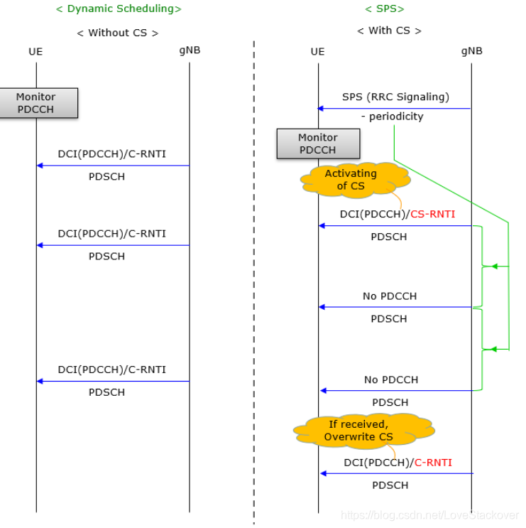
There are two types of scheduling for downlink. One is called ‘Dynamic Scheduling’ and the other one SPS(Semi Persistent Scheduling’). Dynamic scheduling is the mechanism in which each and every PDSCH is scheduled by DCI(DCI 1_0 or DCI 1_1). SPS is the mechanism in which the PDSCH transmission is scheduled by RRC message.

在这里插入图片描述

3. DYNAMIC DOWNLINK SCHEDULING

  • The gain obtained by transmitting to users with favorable radio-link conditions is commonly known as multiuser diversity. The larger the channel variation and the larger the number of users in a cell, the larger the multiuser diversity gain.
  • Lately, there has also been a large interest in various massive multiuser MIMO schemes [55] where a large number of antenna elements are used to create very narrow “beams,” or, expressed differently, isolate the different users in the spatial domain.
    • It can be shown that, under certain conditions, the use of a large number of antennas results in an effect known as “channel hardening.”

Defination :

In NR, the downlink scheduler is responsible for dynamically controlling the device(s) to transmit to. Each of the scheduled devices is provided with a scheduling assignment including information on the set of time frequency resources upon which the device’s DL-SCH is transmitted, the modulation-and-coding scheme, hybrid-ARQ-related information, and multi-antenna parameters.

Common :

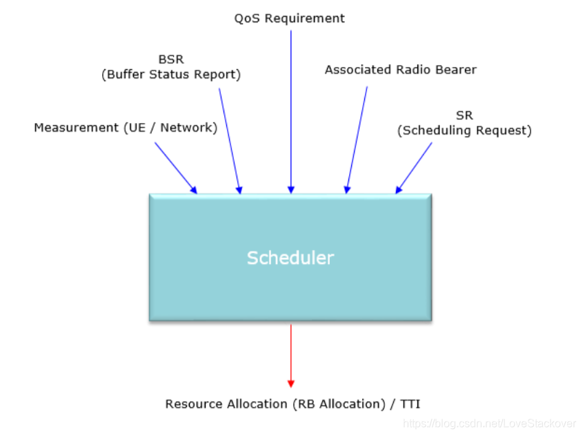
The information needed by the scheduler depends on the specific scheduling strategy implemented, but most
schedulers need information about at least:

  • Channel conditions at the device, including spatial-domain properties;
  • Buffer status of the different data flows;
  • Priorities of the different data flows, including the amount of data pending retransmission.

Information about the channel conditions :

There is a wide range of CSI reports that can be configured where the device reports the channel quality in the time, frequency, and spatial domains.

carrier aggregation:

In the case of carrier aggregation, the scheduling decisions are taken per carrier and the scheduling assignments are transmitted separately for each carrier, that is, a device scheduled to receive data from multiple carriers simultaneously receives multiple PDCCHs.

4. 待解决

  1. In most cases the scheduling assignment is transmitted just before the data on the PDSCH, but the timing information in the scheduling assignment can also schedule in OFDM symbols later in the slot or in later slots.

如何理解时间信息调度呢?

  1. A PDCCH received can either point to the same carrier, known as self-scheduling, or to another carrier, commonly referred to as cross-carrier scheduling (see Fig. 14.1). In the case of cross-carrier scheduling of a carrier with a different numerology than the one upon which the PDCCH was transmitted, timing offsets in the scheduling assignment, for example, which slot the assignment relates to, are interpreted in the PDSCH numerology (and not the PDCCH numerology).
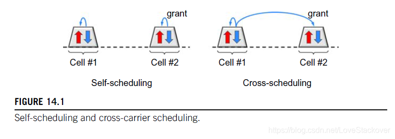
在这里插入图片描述
这里自调度和跨载波调度如何理解呢?

  • 1
    点赞
  • 2
    收藏
    觉得还不错? 一键收藏
  • 0
    评论
Contents Foreword 7 1 Scope 8 2 References 8 3 Abbreviations and Definitions 9 3.1 Abbreviations 9 3.2 Definitions 9 4 Overall Architecture and Functional Split 10 4.1 Overall Architecture 10 4.2 Functional Split 11 4.3 Network Interfaces 13 4.3.1 NG Interface 13 4.3.1.1 NG User Plane 13 4.3.1.2 NG Control Plane 13 4.3.2 Xn Interface 14 4.3.2.1 Xn User Plane 14 4.3.2.2 Xn Control Plane 14 4.4 Radio Protocol Architecture 15 4.4.1 User Plane 15 4.4.2 Control Plane 15 4.5 Multi-RAT Dual Connectivity 16 5 Physical Layer 16 5.1 Waveform, numerology and frame structure 16 5.2 Downlink 17 5.2.1 Downlink transmission scheme 17 5.2.2 Physical-layer processing for physical downlink shared channel 17 5.2.3 Physical downlink control channels 18 5.2.4 Synchronization signal and PBCH 18 5.2.5 Physical layer procedures 19 5.2.5.1 Link adaptation 19 5.2.5.2 Power Control 19 5.2.5.3 Cell search 19 5.2.5.4 HARQ 19 5.3 Uplink 19 5.3.1 Uplink transmission scheme 19 5.3.2 Physical-layer processing for physical uplink shared channel 19 5.3.3 Physical uplink control channel 20 5.3.4 Random access 21 5.3.5 Physical layer procedures 21 5.3.5.1 Link adaptation 21 5.3.5.2 Uplink Power control 21 5.3.5.3 Uplink timing control 21 5.3.5.4 HARQ 21 5.4 Carrier aggregation 21 5.4.1 Carrier aggregation 21 5.4.2 Supplemental Uplink 22 5.5 Transport Channels 22 6 Layer 2 23 6.1 Overview 23 6.2 MAC Sublayer 24 6.2.1 Services and Functions 24 6.2.2 Logical Channels 25 6.2.3 Mapping to Transport Channels 25 6.2.4 HARQ 25 6.3 RLC Sublayer 25 6.3.1 Transmission Modes 25 6.3.2 Services and Functions 26 6.3.3 ARQ 26 6.4 PDCP Sublayer 26 6.4.1 Services and Functions 26 6.5 SDAP Sublayer 27 6.6 L2 Data Flow 27 6.7 Carrier Aggregation 27 6.8 Dual Connectivity 29 6.9 Supplementary Uplink 29 6.10 Bandwidth Adaptation 29 7 RRC 30 7.1 Services and Functions 30 7.2 Protocol States 31 7.3 System Information Handling 31 7.4 Access Control 32 7.5 UE Capability Retrieval framework 32 7.6 Transport of NAS Messages 33 7.7 Carrier Aggregation 33 7.8 Bandwidth Adaptation 33 8 NG Identities 33 8.1 UE Identities 33 8.2 Network Identities 33 9 Mobility and State Transitions 34 9.1 Overview 34 9.2 Intra-NR 34 9.2.1 Mobility in RRC_IDLE 34 9.2.1.1 Cell Selection 34 9.2.1.2 Cell Reselection 35 9.2.2 Mobility in RRC_INACTIVE 35 9.2.2.1 Overview 35 9.2.2.2 Cell Reselection 36 9.2.2.3 RAN-Based Notification Area 36 9.2.2.4 State Transitions 37 9.2.2.4.1 UE triggered transition from RRC_INACTIVE to RRC_CONNECTED 37 9.2.2.4.2 Network triggered transition from RRC_INACTIVE to RRC_CONNECTED 37 9.2.2.5 RNA update 38 9.2.3 Mobility in RRC_CONNECTED 38 9.2.3.1 Overview 38 9.2.3.2 Handover 39 9.2.3.2.1 C-Plane Handling 39 9.2.3.2.2 U-Plane Handling 41 9.2.4 Measurements 41 9.2.5 Paging 43 9.2.6 Random Access Procedure 43 9.2.7 Radio Link Failure 44 9.3 Inter RAT 44 9.3.1 Intra 5GC 44 9.3.1.1 Cell Reselection 44 9.3.1.2 Handover 45 9.3.1.3 Measurements 45 9.3.2 From 5GC to EPC 45 9.3.2.1 Cell Reselection 45 9.3.2.2 Handover 45 9.3.2.3 Measurements 45 9.3.2.4 Data Forwarding 45 9.4 Roaming and Access Restrictions 46 10 Scheduling 46 10.1 Basic Scheduler Operation 46 10.2 Downlink Scheduling 46 10.3 Uplink Scheduling 47 10.4 Measurements to Support Scheduler Operation 47 10.5 Rate Control 47 10.5.1 Downlink 47 10.5.2 Uplink 48 10.6 Activation/Deactivation Mechanism 48 11 UE Power Saving 48 12 QoS 49 13 Security 50 13.1 Overview and Principles 50 13.2 Security Termination Points 51 13.3 State Transitions and Mobility 51 14 UE Capabilities 51 15 Self-Configuration and Self-Optimisation 51 15.1 Definitions 51 15.2 UE Support for self-configuration and self-optimisation 51 15.3 Self-configuration 52 15.3.1 Dynamic configuration of the NG-C interface 52 15.3.1.1 Prerequisites 52 15.3.1.2 SCTP initialization 52 15.3.1.3 Application layer initialization 52 15.3.2 Dynamic Configuration of the Xn interface 52 15.3.2.1 Prerequisites 52 15.3.2.2 SCTP initialization 52 15.3.2.3 Application layer initialization 52 15.3.3 Automatic Neighbour Cell Relation Function 52 15.3.3.1 General 52 15.3.3.2 Intra-system – intra NR Automatic Neighbour Cell Relation Function 52 15.3.3.3 Intra-system – intra E-UTRA Automatic Neighbour Cell Relation Function 53 15.3.3.4 Intra-system – inter RAT Automatic Neighbour Cell Relation Function 53 15.3.3.5 Inter-system Automatic Neighbour Cell Relation Function 53 15.3.4 Xn-C TNL address discovery 53 16 Verticals Support 53 16.1 URLLC 53 16.1.1 Overview 53 16.1.2 LCP Restrictions 53 16.1.3 Packet Duplication 53 16.2 IMS Voice 54 16.3 Network Slicing 54 16.3.1 General Principles and Requirements 54 16.3.2 CN Instance and NW Slice Selection 55 16.3.2.1 CN-RAN interaction and internal RAN aspects 55 16.3.2.2 Radio Interface Aspects 55 16.3.3 Resource Isolation and Management 55 16.3.4 Signalling Aspects 56 16.3.4.1 General 56 16.3.4.2 CN Instance and NW Slice Selection 56 16.3.4.3 UE Context Handling 56 16.3.4.4 PDU Session Handling 57 16.3.4.5 Mobility 58 16.4 Public Warning System 59 Annex A (informative): QoS Handling in RAN 60 A.1 PDU Session Establishment 60 A.2 New QoS Flow without Explicit Signalling 60 A.3 New QoS Flow with NAS Reflective QoS and Explicit RRC Signalling 61 A.4 New QoS Flow with Explicit Signalling 62 A.5 Release of QoS Flow with Explicit Signalling 63 A.6 UE Initiated UL QoS Flow 64 Annex B (informative): Deployment Scenarios 66 B.1 Supplementary Uplink 66 Annex C (informative): Change history 67

“相关推荐”对你有帮助么?

  • 非常没帮助
  • 没帮助
  • 一般
  • 有帮助
  • 非常有帮助
提交
评论
添加红包

请填写红包祝福语或标题

红包个数最小为10个

红包金额最低5元

当前余额3.43前往充值 >
需支付:10.00
成就一亿技术人!
领取后你会自动成为博主和红包主的粉丝 规则
hope_wisdom
发出的红包
实付
使用余额支付
点击重新获取
扫码支付
钱包余额 0

抵扣说明:

1.余额是钱包充值的虚拟货币,按照1:1的比例进行支付金额的抵扣。
2.余额无法直接购买下载,可以购买VIP、付费专栏及课程。

余额充值