


前言:
最近参加了光电赛,校赛运气不好碰到铁板被淘汰了,我是大一菜鸟,只负责宝藏识别部分,花了一个多月学python、研究openmv写出来的代码,虽然技术性不高,但也算一种学习和成长了。
目录
零、预备知识
自己临时找的资料和网课
openmv官方文档:10分钟快速上手 · OpenMV中文入门教程![]() https://book.openmv.cc/quick-starter.htmlPython基础知识:Python导学视频_哔哩哔哩_bilibiliPython导学视频是黑马程序员python教程,8天python从入门到精通,学python看这套就够了的第1集视频,该合集共计164集,视频收藏或关注UP主,及时了解更多相关视频内容。
https://book.openmv.cc/quick-starter.htmlPython基础知识:Python导学视频_哔哩哔哩_bilibiliPython导学视频是黑马程序员python教程,8天python从入门到精通,学python看这套就够了的第1集视频,该合集共计164集,视频收藏或关注UP主,及时了解更多相关视频内容。![]() https://www.bilibili.com/video/BV1qW4y1a7fU?p=1&vd_source=bacf9907e915b4bed671807a9c8859a1
https://www.bilibili.com/video/BV1qW4y1a7fU?p=1&vd_source=bacf9907e915b4bed671807a9c8859a1
一、要识别的图形

1.1 识别要求
己方真宝藏推倒,其他宝藏均不推倒。
1.2 观察图形
假设己方为蓝方,发现己方宝藏外层均为蓝色,真宝藏内层为黄色圆形,假宝藏内层为绿色三角形,敌方同理。
1.3 识别标志
若为真宝藏则对矩形画蓝框,若为假宝藏则画红框。
二、识别思路
思路1.0
1. 识别到矩形确认是宝藏;
2. 在矩形区域内,识别蓝色确认是己方宝藏,若为红色则直接判定为假;
3. 在矩形区域内,确认为己方宝藏条件下,识别到圆形确认为真宝藏,否则为假宝藏;
失败原因:圆是徒手画的,识别效果不好;识别圆形需要加畸变矫正,可能阻碍了矩形的识别。
# 畸变矫正
img = sensor.snapshot().lens_corr(1.8)
思路2.0
1. 识别到矩形确认是宝藏;
2. 在矩形区域内,识别蓝色确认是己方宝藏,若为红色则直接判定为假;
3. 在矩形区域内,确认为己方宝藏条件下,识别到黄色色块确认为真宝藏,否则为假宝藏;
失败原因:假宝藏非常容易被识别为真宝藏,敌方真宝藏也有一定概率被误识别为真宝藏,或者直接没有任何识别反应。可能原因一是因为openmv对绿色色块不敏感,但对黄色色块非常敏感;可能原因二是光线较暗的环境下颜色对比度低,无法识别颜色。
while True:
    clock.tick()
        img = sensor.snapshot()
            for r in img.find_rects(threshold=10000):
                area = r.rect()  # 检测到矩形
                blobs_blue = img.find_blobs(blue_threshold, roi = area)
                if blobs_blue:
                    # 在矩形内检测到蓝色,说明是己方宝藏
                    blobs_yellow = img.find_blobs(yellow_threshold, roi = area)
                    # 在矩形框内检测黄色色块
                    if blobs_yellow:
                        img.draw_rectangle(r.rect(), color = (0, 0, 255))
                        # 在检测到的真宝藏上画蓝框
                        print("真宝藏")
                    else:
                        # 没识别到黄色色块,说明是假宝藏
                        print("假宝藏")
                else:
                     # 没检测到蓝色, 说明是敌方宝藏
                     print("敌方宝藏")
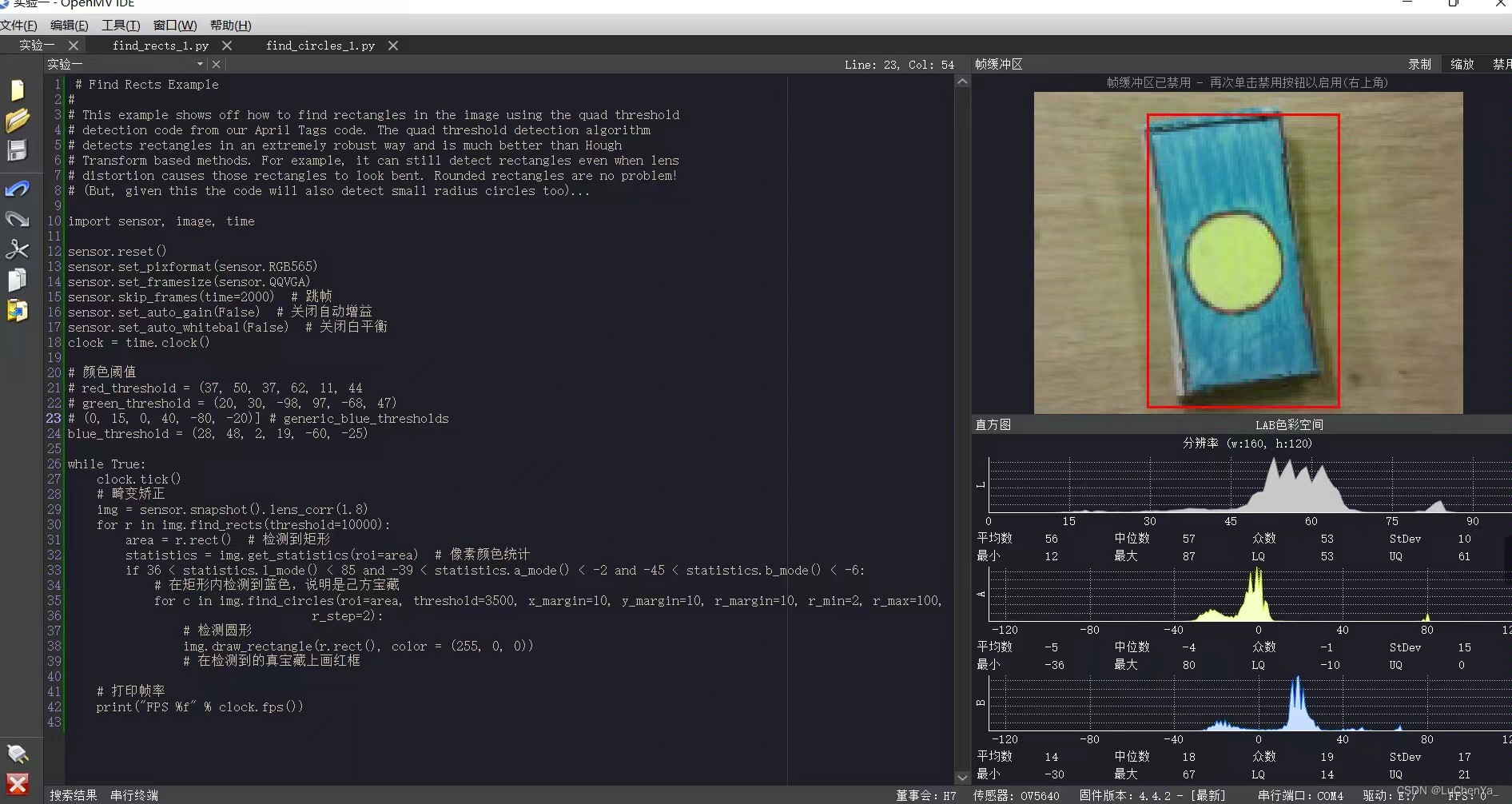
图里的代码是很早的版本,看看效果就行,我后面的效果图因为比赛寄了,全删完了回收站都找不到QAQ
思路3.0
1. 识别到矩形确认是宝藏;
2. 在矩形区域内,识别蓝色确认是己方宝藏,若为红色则直接判定为假;
3. 在矩形区域内,确认为己方宝藏条件下,识别到黄色色块确认为真宝藏;
4. 为尽量避免假宝藏的误识别,我将假宝藏的判定条件改为:在矩形区域内,确认为己方宝藏条件下,识别到绿色色块且绿色色块的density在0.40到0.60之间(三角形判定)。
5. 同时,将敌方宝藏的判定条件改为在矩形内检测红色色块。
while True:
    clock.tick()
        img = sensor.snapshot()
            for r in img.find_rects(threshold=10000):
                area = r.rect()  # 检测到矩形
                blobs_blue = img.find_blobs(blue_threshold, roi = area)
                if blobs_blue:
                    # 在矩形内检测到蓝色,说明是己方宝藏
                    blobs_yellow = img.find_blobs(yellow_threshold, roi = area)
                    # 在矩形框内内检测黄色色块
                    if blobs_yellow:
                        img.draw_rectangle(r.rect(), color = (0, 0, 255))
                        # 在检测到的真宝藏上画蓝框
                        print("真宝藏")
                    else:
                        for blob_green in img.find_blobs(green_threshold, roi = area):
                            if blob_green and blob_green.density() > 0.40 and blob_green.density() < 0.60 :
                                img.draw_cross(blob_green.cx(), blob_green.cy())
                                # 在三角形上画十字
                                img.draw_rectangle(r.rect(), color = (255, 255, 255))
                                # 在检测到的假宝藏上画白框
                                print("假宝藏")
                else:
                    blobs_red = img.find_blobs(red_threshold, roi = area)
                    if blobs_red:
                        # 没检测到蓝色,检测到红色,说明是敌方宝藏
                        print("敌方宝藏")
由于时间有限没能做进一步精进,所以这是关于图像识别部分的最终版。
事实上,由于光线变化和openmv本身的未知硬件问题,openmv在小车上脱机运行时,识别假宝藏仍然会出现偶尔的误识别现象,但对真宝藏和敌方宝藏的识别效果基本无误。
碎碎念:我这些思路是简化版的,实际上由于我是新手,Python是现学的,openmv官方文档是现看的,写出最终识别程序经历了很多个版本迭代,中间为了识别效果更好,调了很多次颜色阈值,我本来打算过了校赛就继续调试参数和优化程序,emmm
三、openmv向小车主控实时发送识别结果

openmv对宝藏的识别是在运动的小车上进行的,所以识别到宝藏后需要向小车主控部分发送信息进行处理。
一开始的想法是openmv与STM32串口通信。
1、openmv与STM32串口通信
1.1 硬件连接
openmv的P4、P5引脚顺序连接STM32最小系统板的B11、B10,STM32还需要加个OLED用于测试识别和通信效果。
1.2 openmv部分
1.2.1 前置部分
import sensor, image, time, pyb
from pyb import UART
import json
import ustruct

sensor.reset()
sensor.set_pixformat(sensor.RGB565)
sensor.set_framesize(sensor.QQVGA)
sensor.skip_frames(time=2000)  # 跳帧
sensor.set_auto_gain(False)  # 关闭自动增益
sensor.set_auto_whitebal(False)  # 关闭白平衡
clock = time.clock()

# 色块阈值
blue_threshold = (31, 66, -37, -9, 5, -32)
yellow_threshold = (50, 78, -54, 108, 20, 78)

# 测距常数
k = 950
1.2.2 串口配置
# 串口配置
uart = UART(3,115200)   #定义串口3变量,设置波特率
uart.init(115200, bits=8, parity=None, stop=1) # init with given parameters

# 发送函数
def send_data_packet(x,y):
    temp = ustruct.pack("<bbhhhh",             #格式为俩个字符俩个短整型
                   0x2C,                       #帧头1
                   0x12,                       #帧头2
                   short(x), # up sample by 2  #数据1
                   short(y), # up sample by 2  #数据2

                   0x5B)
    uart.write(temp);                           #串口发送

# 这里使用了数据包的形式发送数据,将一帧的数据包装,并发送给Stm32,
# 此数据包中的包头非常重要,也就是0x2C以及0x12,这两个数据便与Stm32接收中断中进行判断,
# 以确保数据的正确性。
# 对于数据包格式,此等的使用规划:
#pack各字母对应类型
#x   pad byte        no value            1
#c   char            string of length 1  1
#b   signed char     integer             1
#B   unsigned char   integer             1
#?   _Bool           bool                1
#h   short           integer             2
#H   unsigned short  integer             2
#i   int             integer             4
#I   unsigned int    integer or long     4
#l   long            integer             4
#L   unsigned long   long                4
#q   long long       long                8
#Q   unsigned long   long                8
#f   float           float               4
#d   double          float               8
#s   char[]          string              1
#p   char[]          string              1
#P   void *          long
1.2.3识别部分
while True:
    clock.tick()
        img = sensor.snapshot()
            for r in img.find_rects(threshold=10000):
                area = r.rect()  # 检测到矩形
                blobs_blue = img.find_blobs(blue_threshold, roi = area)
                if blobs_blue:
                    # 在矩形内检测到蓝色,说明是己方宝藏
                    blobs_yellow = img.find_blobs(yellow_threshold, roi = area)
                    # 在矩形框内内检测黄色色块
                    if blobs_yellow:
                        b = find_max(blobs_yellow)  # 将返回数据赋值给b
                        Lm = (b[2] + b[3]) / 2
                        length = k / Lm
                        print(length)
                        img.draw_rectangle(r.rect(), color = (0, 0, 255))
                        # 在检测到的真宝藏上画蓝框
                        print("真宝藏")
                        send_data_packet(length, 1)
                    else:
                        for blob_green in img.find_blobs(green_threshold, roi = area):
                            if blob_green and blob_green.density() > 0.40 and blob_green.density() < 0.60 :
                                img.draw_cross(blob_green.cx(), blob_green.cy())
                                # 在三角形上画十字
                                img.draw_rectangle(r.rect(), color = (255, 255, 255))
                                # 在检测到的假宝藏上画白框
                                print("假宝藏")
                                send_data_packet(0, 0)
                else:
                    blobs_red = img.find_blobs(red_threshold, roi = area)
                    if blobs_red:
                        # 没检测到蓝色,检测到红色,说明是敌方宝藏
                        print("敌方宝藏")
                        send_data_packet(0,0)
1.3 STM32部分
1.3.1 USART.c
#include "stm32f10x.h"                  // Device header

void USART3_Init(void)
{
	//USART3_TX PB10
	//USART3_RX PB11
	//GPIO端口配置
	GPIO_InitTypeDef GPIO_InitStructure;
	USART_InitTypeDef USART_InitStructure;
	NVIC_InitTypeDef NVIC_InitStructure;

	//使能GPIOB的时钟
	RCC_APB1PeriphClockCmd(RCC_APB1Periph_USART3,ENABLE);
	RCC_APB2PeriphClockCmd(RCC_APB2Periph_GPIOB,ENABLE);

	//初始化B10引脚——RX
	GPIO_InitStructure.GPIO_Mode = GPIO_Mode_AF_PP;//复用推挽输出
	GPIO_InitStructure.GPIO_Pin = GPIO_Pin_10;
	GPIO_InitStructure.GPIO_Speed = GPIO_Speed_50MHz;
	GPIO_Init(GPIOB,&GPIO_InitStructure);

	//初始化B11引脚——TX
	GPIO_InitStructure.GPIO_Mode = GPIO_Mode_IN_FLOATING;//浮空输入
	GPIO_InitStructure.GPIO_Pin = GPIO_Pin_11;
	GPIO_InitStructure.GPIO_Speed = GPIO_Speed_50MHz;
	GPIO_Init(GPIOB,&GPIO_InitStructure);

	//串口中断配置
	NVIC_InitStructure.NVIC_IRQChannel = USART3_IRQn;
	NVIC_InitStructure.NVIC_IRQChannelCmd = ENABLE;
	NVIC_InitStructure.NVIC_IRQChannelPreemptionPriority = 0;
	NVIC_InitStructure.NVIC_IRQChannelSubPriority = 2;
	NVIC_Init(&NVIC_InitStructure);

	USART_InitStructure.USART_BaudRate = 115200;
    //配置波特率
	USART_InitStructure.USART_WordLength = USART_WordLength_8b;
    //字长八位
	USART_InitStructure.USART_StopBits = USART_StopBits_1;
    //一个停止位
	USART_InitStructure.USART_Parity = USART_Parity_No;
    //无奇偶校验
	USART_InitStructure.USART_HardwareFlowControl = USART_HardwareFlowControl_None;
    //无数据流控制
	USART_InitStructure.USART_Mode = USART_Mode_Rx | USART_Mode_Tx;
     //收发模式
	USART_Init(USART3, &USART_InitStructure);


	USART_ITConfig(USART3, USART_IT_RXNE, ENABLE); //开启串口接收中断
	USART_Cmd(USART3, ENABLE);                     //使能串口3
	USART_ClearFlag(USART3, USART_FLAG_TC);        //清除标志位
}
1.3.2 main.c
#include "stm32f10x.h"  // Device header
#include "OLED.h"
#include "USART.h"

int main(void)
{
	OLED_Init();
	USART3_Init();
	while(1)
	{
    }
}
//串口中断函数
void USART3_IRQHandler(void)
{
	uint8_t Data;
	uint8_t i;
	static uint8_t RxCounter1 = 0;
	static uint8_t RxBuffer1[7] = {0};//存放数据数组
	static uint8_t RxState = 0;	      //数据接收状态位
	static uint8_t RxFlag = 0;

	if( USART_GetITStatus(USART3,USART_IT_RXNE)!=RESET)  	   //触发接收中断
	{
		USART_ClearITPendingBit(USART3,USART_IT_RXNE);         //清除中断标志位
		Data = USART_ReceiveData(USART3);				       //接收数据

		if(RxState == 0 && Data == 0x2C)                       //0x2c帧头开始数据接收处理
		{
			RxState=1;
			RxBuffer1[RxCounter1++] = Data;
		}
		else if(RxState==1&&Data==0x12)  //0x12帧头
		{
			RxState=2;
			RxBuffer1[RxCounter1++] = Data;
		}
		else if(RxState==2)              //正式接收数据
		{
			RxBuffer1[RxCounter1++] = Data;

			if(RxCounter1 >= 7 || Data == 0x5B)       //RxBuffer1接收数据结束
			{
				RxState = 3;
				RxFlag = 1;
				length = (RxBuffer1[RxCounter1-4]<<8) + RxBuffer1[RxCounter1-5];
				Flag = (RxBuffer1[RxCounter1-2]<<8) + RxBuffer1[RxCounter1-3];
                //后来者是高八位
			}
		}
		else if(RxState==3)		//检测数据接收结束标志
		{
			if(RxBuffer1[RxCounter1-1] == 0x5B)
			{
				USART_ITConfig(USART3,USART_IT_RXNE,DISABLE);//关闭串口中断
				if(RxFlag == 1)
				{
					OLED_ShowNum(1, 1 ,length, 3);
					OLED_ShowNum(2, 1 ,Flag, 3);
				}
				RxCounter1 = 0;
				RxState = 0;
				USART_ITConfig(USART3,USART_IT_RXNE,ENABLE);//emmm
			}
			else   //接收错误
			{
				RxState = 0;
				RxCounter1 = 0;
				for(i = 0;i < 7;i++)
				{
					RxBuffer1[i] = 0x00;      //存放数据数组清零
				}
			}
		}
		else   //接收异常
		{
			RxState = 0;
			RxCounter1 = 0;
			for(i = 0;i < 7;i++)
			{
				RxBuffer1[i] = 0x00;      //存放数据数组清零
			}
		}
	}
}
这里发送的两个数据,一个是宝藏和摄像头的距离length,另一个是检测标志位Flag,真为1,其他为假。
然后学长说去掉串口通信直接换电平检测,更简单,我:ok.
2、电平检测
去掉串口,加上定时器不断检测引脚7、8电平用于判断识别正确性。
2.1 增加代码
from pyb import Pin
from pyb import Timer

# 颜色阈值,emmm光线不稳定,多测了几套阈值数据
green_threshold = [(21, 48, -44, 14, 39, 16),
                   (23, 43, -49, -22, 37, 16)]

blue_threshold = [(31, 66, -37, -9, 5, -32),
                   (23, 54, -10, -99, -29, 6)]
blue_threshold_01 = (36, 56, -34, 2, -45, -12)

yellow_threshold = (50, 78, -54, 108, 20, 78)

red_threshold = [ (51, 17, 48, 3, 42, -4),
                  (35, 11, 41, 6, 52, -1),
                  (20, 58, -41, 11, -14, 35), # 有光
                  (8, 40, -39, 10, -10, 20), # 暗
                  (19, 45, 19, 41, 30, -13)]
red_threshold_01 = (19, 45, 19, 41, 30, -13)

P7_State = 2
P8_State = 2

P7_Out = Pin('P7',Pin.OUT_PP)  # P7设置成推挽输出
P8_Out = Pin('P8',Pin.OUT_PP)  # P8设置成推挽输出

tim = Timer(2, freq=1)      # 1hz,1s检测一次

def tick(timer):      #这里开启了一个定时器
    global key1, P7_State, P8_State
    key1 = pin1.value()
    P7_State = P7_Out.value()  # 获取P7的引脚状态,0 or 1
    P8_State = P8_Out.value()  # 获取P8的引脚状态,0 or 1

tim.callback(tick)
2.2 主程序
if __name__ == "__main__":
    # 真01,假10,敌方10
    while True:
        clock.tick()
        img = sensor.snapshot()
        if key1 == 1:
            for r in img.find_rects(threshold=10000):
                area = r.rect()  # 检测到矩形
                blobs_blue = img.find_blobs([blue_threshold_01], roi = area)
                if blobs_blue:
                    # 在矩形内检测到蓝色,说明是己方宝藏
                    blobs_yellow = img.find_blobs([yellow_threshold], roi = area)
                    # 在矩形框内内检测黄色色块
                    if blobs_yellow:
                        img.draw_rectangle(r.rect(), color = (0, 0, 255))
                        # 在检测到的真宝藏上画红框
                        P7_Out.low()   # 设置p_out引脚为低
                        P8_Out.high()  # 设置p_out引脚为高
                        print("真宝藏", P7_State, P8_State)
                    else:
                        for blob_green in img.find_blobs(green_threshold, roi = area):
                            if blob_green and blob_green.density() > 0.45 and blob_green.density() < 0.60 :
                                img.draw_cross(blob_green.cx(), blob_green.cy())
                                # 在三角形上画十字
                                img.draw_rectangle(r.rect(), color = (255, 255, 255))
                                # 在检测到的假宝藏上画白框
                                P7_Out.high()  # 设置p_out引脚为高
                                P8_Out.low()   # 设置p_out引脚为低
                                print("假宝藏", P7_State, P8_State)
                else:
                    blobs_red = img.find_blobs([red_threshold_01], roi = area)
                    if blobs_red:
                        # 没检测到蓝色,检测到红色,说明是敌方宝藏
                        P7_Out.high()  # 设置p_out引脚为低
                        P8_Out.low()   # 设置p_out引脚为低
                        print("敌方宝藏", P7_State, P8_State)
到目前为止,识别宝藏,对应输出引脚电平,就算完了,然而,实际比赛自己是蓝队还是红队是不确定的,所以还要设置一套基于红方的识别程序,只要切换色块阈值就好了。
四、按键切换红蓝队
把小开关或者按键连到openmv的P1上,另一端接正极或负极,按下就可以对P1电平变换。
再加一个功能,识别到真宝藏,红灯闪烁,方便观察现象。
# Untitled - By: Lenovo - 星期六 7月 8 2023

import sensor, image, time, pyb
from pyb import LED
from pyb import Pin
from pyb import Timer

sensor.reset()
sensor.set_pixformat(sensor.RGB565)
sensor.set_framesize(sensor.QQVGA)
sensor.skip_frames(time=2000)  # 跳帧
sensor.set_auto_gain(False)  # 关闭自动增益
sensor.set_auto_whitebal(False)  # 关闭白平衡
clock = time.clock()

# 颜色阈值
green_threshold = [(26, 14, -34, -21, 11, 28)]

blue_threshold = [(26, 53, -29, -4, -34, -4),
                  (13, 32, 6, -22, -5, -32)]
blue_threshold_01 = (36, 56, -34, 2, -45, -12)

yellow_threshold = [(35, 82, -71, 14, 53, 10),
                    (67, 53, -87, -9, 51, 21)]

red_threshold = [(19, 40, 2, 48, 3, 36),
                 (6, 23, 8, 36, -3, 30),
                 (17, 38, -2, 32, -9, 26)]
red_threshold_01 = (19, 45, 19, 41, 30, -13)

P7_State = 2
P8_State = 2

# 设置pin1为输入口
pin1 = Pin('P1', Pin.IN, Pin.PULL_UP)
P7_Out = Pin('P7',Pin.OUT_PP)  # P7设置成推挽输出
P8_Out = Pin('P8',Pin.OUT_PP)  # P8设置成推挽输出

tim = Timer(2, freq=1)      # 1hz,1s检测一次

def tick(timer):      #这里开启了一个定时器
    global key1, P7_State, P8_State
    key1 = pin1.value()
    P7_State = P7_Out.value()  # 获取P7的引脚状态,0 or 1
    P8_State = P8_Out.value()  # 获取P8的引脚状态,0 or 1

tim.callback(tick)

#定义寻找色块面积最大的函数,最终版本没用到这个函数
def find_max(blobs):
    max_size=0
    for blob in blobs:
        if blob.pixels() > max_size:
            max_blob=blob
            max_size = blob.pixels()
    return max_blob


# 按键切换
key1 = 0

LED_R = pyb.LED(1) # Red LED = 1, Green LED = 2, Blue LED = 3, IR LEDs = 4.

if __name__ == "__main__":
    # 真01,假10,敌方10
    while True:
        clock.tick()
        img = sensor.snapshot()
        if key1 == 1:
            for r in img.find_rects(threshold=10000):
                area = r.rect()  # 检测到矩形
                blobs_blue = img.find_blobs(blue_threshold, roi = area)
                if blobs_blue:
                    # 在矩形内检测到蓝色,说明是己方宝藏
                    blobs_yellow = img.find_blobs(yellow_threshold, roi = area)
                    # 在矩形框内内检测黄色色块
                    if blobs_yellow:
                        img.draw_rectangle(r.rect(), color = (0, 0, 255))
                        # 在检测到的真宝藏上画蓝框
                        P7_Out.low()   # 设置p_out引脚为低
                        P8_Out.high()  # 设置p_out引脚为高
                        print("真宝藏", P7_State, P8_State)
                        LED_R.on()
                        time.sleep_ms(150)
                        LED_R.off()
                    else:
                        for blob_green in img.find_blobs(green_threshold, roi = area):
                            if blob_green and blob_green.density() > 0.35 and blob_green.density() < 0.70 :
                                img.draw_cross(blob_green.cx(), blob_green.cy())
                                # 在三角形上画十字
                                img.draw_rectangle(r.rect(), color = (255, 255, 255))
                                # 在检测到的假宝藏上画白框
                                P7_Out.high()  # 设置p_out引脚为高
                                P8_Out.low()   # 设置p_out引脚为低
                                print("假宝藏", P7_State, P8_State)
                else:
                    blobs_red = img.find_blobs(red_threshold, roi = area)
                    if blobs_red:
                        # 没检测到蓝色,检测到红色,说明是敌方宝藏
                        P7_Out.high()  # 设置p_out引脚为高
                        P8_Out.low()   # 设置p_out引脚为低
                        print("敌方宝藏", P7_State, P8_State)

        else:
            for r in img.find_rects(threshold=10000):
                area = r.rect()  # 检测到矩形
                blobs_red = img.find_blobs(red_threshold, roi = area)
                if blobs_red:
                    # 在矩形内检测到红色,说明是己方宝藏
                    blobs_yellow = img.find_blobs(yellow_threshold, roi = area)
                    # 在矩形框内内检测黄色色块
                    if blobs_yellow:
                        img.draw_rectangle(r.rect(), color = (255, 0, 0))
                        # 在检测到的真宝藏上画红框
                        P7_Out.low()   # 设置p_out引脚为低
                        P8_Out.high()  # 设置p_out引脚为高
                        print("真宝藏", P7_State, P8_State)
                        LED_R.on()
                        time.sleep_ms(150)
                        LED_R.off()
                    else:
                        for blob_green in img.find_blobs(green_threshold, roi = area):
                            if blob_green and blob_green.density() > 0.35 and blob_green.density() < 0.70 :
                                img.draw_cross(blob_green.cx(), blob_green.cy())
                                # 在三角形上画十字
                                img.draw_rectangle(r.rect(), color = (255, 255, 255))
                                # 在检测到的假宝藏上画白框
                                P7_Out.high()  # 设置p_out引脚为高
                                P8_Out.low()   # 设置p_out引脚为低
                                print("假宝藏", P7_State, P8_State)
                else:
                    blobs_blue = img.find_blobs(blue_threshold, roi = area)
                    if blobs_blue:
                        # 没检测到红色,检测到蓝色,说明是敌方宝藏
                        P7_Out.high()  # 设置p_out引脚为高
                        P8_Out.low()   # 设置p_out引脚为低
                        print("敌方宝藏", P7_State, P8_State)
这就是脱机运行的最终版了,光线充足的环境下识别效果还可以,可惜比赛寄了。
后面想到啥再补,有错误可以提。


 891
891


 被折叠的 条评论
为什么被折叠?
被折叠的 条评论
为什么被折叠?
 到【灌水乐园】发言


