


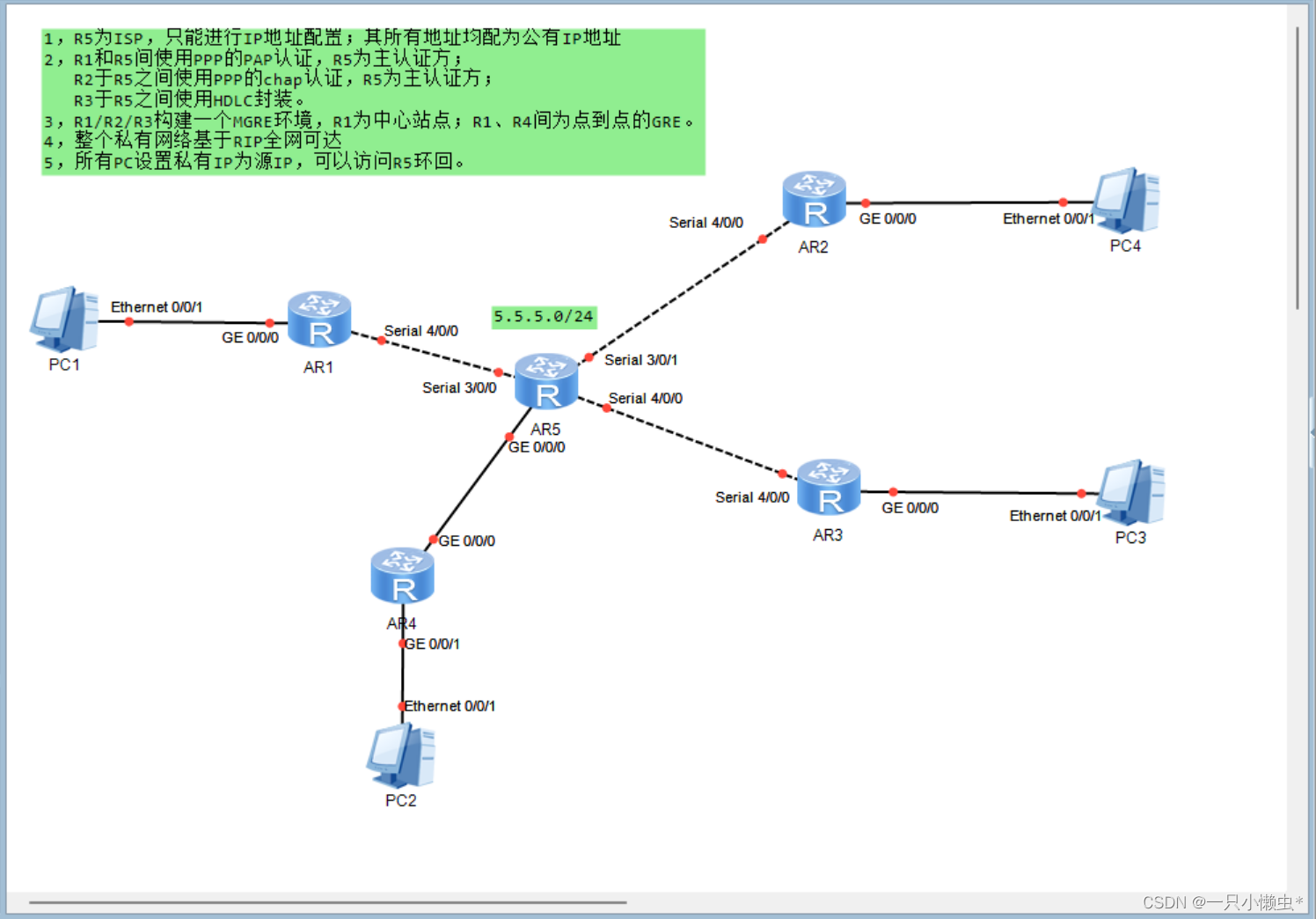
首先,我们需要先创建拓扑模型,其次对每个网段和环回进行IP地址的规划
对各个路由器进行IP配置
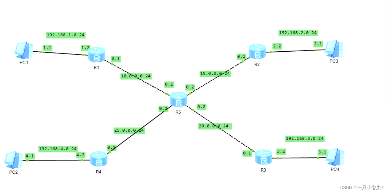
[r1-GigabitEthernet0/0/0]ip add 192.168.1.1 24
[r1-Serial0/0/0]ip add 10.0.0.1 24

[r2-GigabitEthernet0/0/0]ip add 192.168.2.1 24
[r2-Serial0/0/1]ip add 15.0.0.1 24

[r3-GigabitEthernet0/0/0]ip add 192.168.3.1 24
[r3-Serial0/0/1]ip add 20.0.0.1 24

[r4-GigabitEthernet0/0/1]ip add 192.168.4.1 24
[r4-GigabitEthernet0/0/0]ip add 25.0.0.1 24

[isp-Serial0/0/0]ip add 10.0.0.2 24
[isp-Serial0/0/1]ip add 15.0.0.2 24
[isp-GigabitEthernet0/0/0]ip add 25.0.0.2 24
[isp-Serial0/0/2]ip add 20.0.0.2 24
[isp-LoopBack0]ip add 5.5.5.1 24
对除isp之外的路由器写缺省路由
[r1]ip route-static 0.0.0.0 0 10.0.0.2
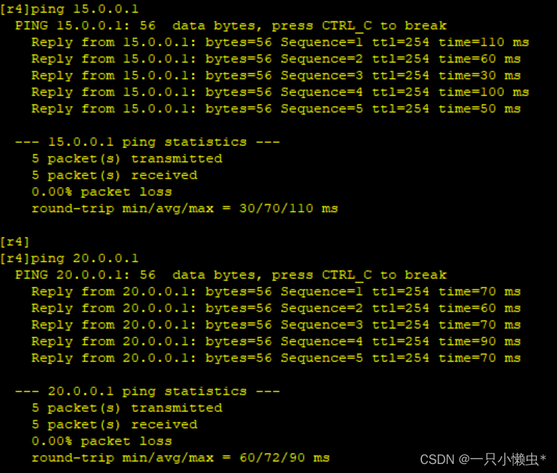
[r2]ip route-static 0.0.0.0 0 15.0.0.2
[r3]ip route-static 0.0.0.0 0 20.0.0.2
[r4]ip route-static 0.0.0.0 0 25.0.0.2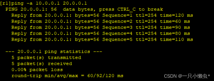
R1和R5间使用PPP的PAP认证,R5为主认证方
[r1-aaa]local-user admin password cipher 12345
[r1-aaa]local-user admin service-type ppp
[r1-Serial0/0/0]ppp authentication-mode pap
[isp-Serial0/0/0]ppp pap local-user admin password cipher 123456
[isp-Serial0/0/0]shutdown
[isp-Serial0/0/0]undo shutdown 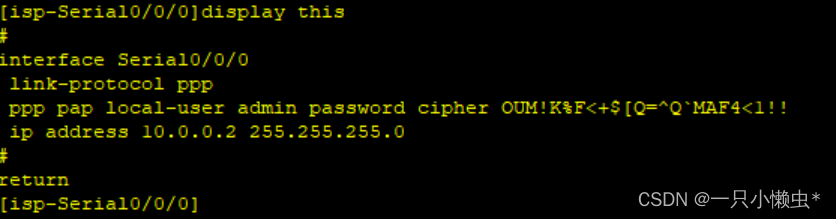
R2于R5之间使用PPP的chap认证,R5为主认证方
[r2-Serial0/0/1]ppp chap user admin
[r2-Serial0/0/1]ppp chap password cipher 123456

[isp-Serial0/0/1]ppp authentication-mode chap
[isp-Serial0/0/1]shutdown
[isp-Serial0/0/1]undo shutdown
[isp-Serial0/0/1]display this 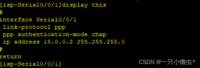
R3于R5之间使用HDLC封装
[r3-Serial0/0/1]link-protocol hdlc
[isp-Serial0/0/2]link-protocol hdlc 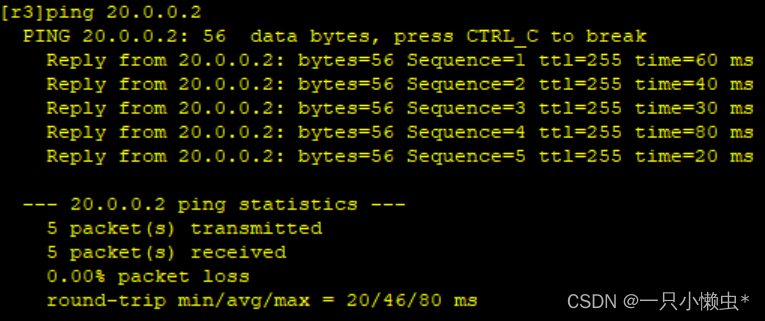


 3760
3760


 被折叠的 条评论
为什么被折叠?
被折叠的 条评论
为什么被折叠?
 到【灌水乐园】发言


