


目标:PC1和PC2实现通信,FW1提供两个出口,ISP1和ISP2.
思路:FW1配置静态默认路由,出接口为G1/0/1和G1/0/2. 两个出口做基于地址池的NAT即可。
橙色区域做动态路由即可,这里是OSPF,忽略其合理性。
基础配置:
FW1:防火墙初始化后配置思路,基础配置包括:IP地址、路由和安全策略。
# IP地址

interface GigabitEthernet1/0/0
 ip address 192.168.1.254 255.255.255.0
#
interface GigabitEthernet1/0/1
 ip address 198.51.100.1 255.255.255.252
#
interface GigabitEthernet1/0/2
 ip address 203.0.113.1 255.255.255.252

# 路由
ip route-static 0.0.0.0 0.0.0.0 GigabitEthernet1/0/1 198.51.100.2
ip route-static 0.0.0.0 0.0.0.0 GigabitEthernet1/0/2 203.0.113.2

# 安全区域
[FW1]display current-configuration configuration zone
2023-05-26 13:29:56.620

firewall zone trust
 add interface GigabitEthernet1/0/0

firewall zone name isp1
 set priority 10
 add interface GigabitEthernet1/0/1
#
firewall zone name isp2
 set priority 20
 add interface GigabitEthernet1/0/2
地址池配置:
#
nat address-group addgroup1
 mode pat
 route enable
 section 0 198.51.100.10 198.51.100.12
#
nat address-group addgroup2
 route enable
 mode pat
 section 0 203.0.113.10 203.0.113.12
NAT策略:
nat-policy
 rule name policy_nat1
  source-zone trust
  destination-zone isp1
  source-address 192.168.1.0 mask 255.255.255.0
  action source-nat address-group addgroup1
 rule name policy_nat2
  source-zone trust
  destination-zone isp2
  source-address 192.168.1.0 mask 255.255.255.0
  action source-nat address-group addgroup2
安全策略:
security-policy
 rule name policy1
  source-zone trust
  destination-zone isp1
  destination-zone isp2
  source-address 192.168.1.0 mask 255.255.255.0
  action permit
外部三台路由器配置:
# ISP1
# ## IP地址
#
interface GigabitEthernet0/0/0
 ip address 198.51.100.2 255.255.255.0
#
interface GigabitEthernet0/0/1
 ip address 200.1.1.1 255.255.255.0

# ## 路由
#
ospf 1
 import-route static
 area 0.0.0.0
  network 198.51.100.0 0.0.0.255
  network 200.1.1.0 0.0.0.255
#
ip route-static 198.51.100.10 255.255.255.255 GigabitEthernet0/0/0 198.51.100.1
ip route-static 198.51.100.11 255.255.255.255 GigabitEthernet0/0/0 198.51.100.1
ip route-static 198.51.100.12 255.255.255.255 GigabitEthernet0/0/0 198.51.100.1


# ISP2
# ## IP地址
interface GigabitEthernet0/0/0
 ip address 203.0.113.2 255.255.255.252
#
interface GigabitEthernet0/0/1
 ip address 201.1.1.1 255.255.255.0

# ## 路由
#
ospf 1
 import-route static
 area 0.0.0.0
  network 201.1.1.0 0.0.0.255
  network 203.0.113.0 0.0.0.255
#
ip route-static 203.0.113.10 255.255.255.255 GigabitEthernet0/0/0 203.0.113.1
ip route-static 203.0.113.11 255.255.255.255 GigabitEthernet0/0/0 203.0.113.1
ip route-static 203.0.113.12 255.255.255.255 GigabitEthernet0/0/0 203.0.113.1


# AR3
# ## IP地址
#
interface GigabitEthernet0/0/0
 ip address 200.1.1.2 255.255.255.0
#
interface GigabitEthernet0/0/1
 ip address 202.1.1.2 255.255.255.0
#
interface GigabitEthernet0/0/2
 ip address 201.1.1.2 255.255.255.0

# ## 路由
#
ospf 1
 area 0.0.0.0
  network 200.1.1.0 0.0.0.255
  network 201.1.1.0 0.0.0.255
  network 202.1.1.0 0.0.0.255
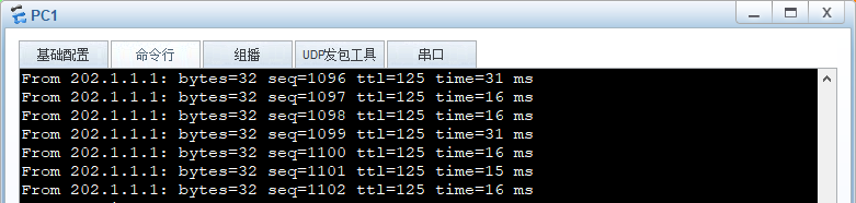
此时PC1和PC2通信测试:
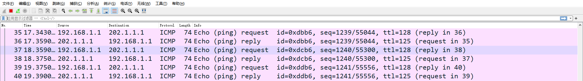
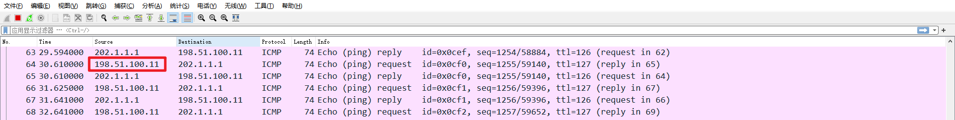
防火墙前后接口抓包:
地址转换前:
地址转换后:
此实验遗留问题:
能否将两个出接口配置到一个相同的安全区域,如untrust,会不会又问题?


 1905
1905


 被折叠的 条评论
为什么被折叠?
被折叠的 条评论
为什么被折叠?
 到【灌水乐园】发言


