


一、简介
Firmata是一个PC与MCU通讯的一个常用协议。其遵旨是能与任何主机PC软件包兼容。到目前为止,已经得到不少语言的支持,这样可方便地将对协议的支持加入软件系统中。Firmata起初是针对于PC与Arduino通讯的固件(Firmware),其目标是让开发者可以通过PC软件完全地控件Arduino。

二、Firmata协议详解
I/O支持
- 超过16路模拟通道
- 超过128(16 * 8-bit ports)路数字通道
消息类型
/* This protocol uses the MIDI message format, but does not use the whole
 * protocol.  Most of the command mappings here will not be directly usable in
 * terms of MIDI controllers and synths.  It should co-exist with MIDI without
 * trouble and can be parsed by standard MIDI interpreters.  Just some of the
 * message data is used differently.
 *
 * MIDI format: http://www.harmony-central.com/MIDI/Doc/table1.html
 *
 *                              MIDI
 * type                command  channel    first byte            second byte
 *----------------------------------------------------------------------------
 * analog I/O message    0xE0   pin #      LSB(bits 0-6)         MSB(bits 7-13)
 * digital I/O message   0x90   port       LSB(bits 0-6)         MSB(bits 7-13)
 * report analog pin     0xC0   pin #      disable/enable(0/1)   - n/a -
 * report digital port   0xD0   port       disable/enable(0/1)   - n/a -
 *
 * sysex start           0xF0
 * set pin mode(I/O)     0xF4              pin # (0-127)         pin state(0=in)
 * sysex end             0xF7
 * protocol version      0xF9              major version         minor version
 * system reset          0xFF
 *
 */
/* SysEx-based commands (0x00-0x7F) are used for an extended command set.
 *
 * type                command  first byte       second byte      ...
 *-----------------------------------------------------------------------------
 * string                0x71   char *string ...
 * firmware name/version 0x79   major version   minor version     char *name...
 */
该协议使用了MIDI消息格式,但并非MIDI消息格式的完整实现,Firmata中大多数命令不能直接按MIDI规定的的术语来使用。
但可与MIDI兼容并可被任何标准MIDI解释器兼容。仅有部分消息数据的使用是不同的。
MIDI消息格式
| 类型 | 命令 | MIDI通道 | 第一字节 | 第二字节 |
| 模拟IO消息 | 0xE0 | 引脚# | 低字节(0-6) | 高字节(7-13) |
| 数字IO消息 | 0x90 | 端口 | 低字节(0-6) | 高字节(7-13) |
| 报告模拟引脚 | 0xC0 | 引脚# | 禁止/使能(0/1) | |
| 报告数字端口 | 0xD0 | 端口 | 禁止/使能(0/1) | |
| sysex命令起始 | 0xF0 | |||
| 引脚模式设置 | 0xF4 | 引脚# | 引脚状态(0=输入) | |
| sysex命令停止 | 0xF7 | |||
| 协议版本 | 0xF9 | 主版本 | 次版本 | |
| 系统重启 | 0xFF | |||
| 基于sysex的命令 | ||||
| 字符串 | 0x71 | char *string ... | ||
| 固件版本 | 0x79 | 主版本 | 次版本 | char *name... |
数据消息详解
/* two byte digital data format    两字节数字数据格式
 * 0  digital data, 0x90-0x9F, (MIDI NoteOn, but different data format)    数字数据,0x90-0x9F
 * 1  digital pins 0-6 bitmask    数字引脚0-6位标志掩码
 * 2  digital pins 7-13 bitmask    数字引脚7-13位标志掩码
 */
/* analog 14-bit data format    14位模拟数据格式
 * 0  analog pin, 0xE0-0xEF, (MIDI Pitch Wheel)    模拟引脚,0xE0-0xEF
 * 1  analog least significant 7 bits    模拟最低有效位7位
 * 2  analog most significant 7 bits     模拟最高有效位7位
 */
/* version report format
 * -------------------------------------------------
 * 0  version report header (0xF9) (MIDI Undefined)
 * 1  major version (0-127)
 * 2  minor version (0-127)
 */
控制消息详解
/* set pin mode设置引脚模式
 * 1  set digital pin mode (0xF4) (MIDI Undefined)
 * 2  pin number (0-127)
 * 3  state (INPUT/OUTPUT/ANALOG/PWM/SERVO, 0/1/2/3/4)
 */
/* toggle analogIn reporting by pin
 * 0  toggle digitalIn reporting (0xC0-0xCF) (MIDI Program Change)
 * 1  disable(0)/enable(non-zero)
 */
/* toggle digital port reporting by port
 * 0  toggle digital port reporting (0xD0-0xDF) (MIDI Aftertouch)
 * 1  disable(0)/enable(non-zero)
 */
/* request version report
 * 0  request version report (0xF9) (MIDI Undefined)
 */
Sysex消息格式
The idea for SysEx is to have a second command space using the first byte after the SysEx Start byte. The key difference is that the data can be of any size, rather than just one or two bytes for standard MIDI messages.
SysEX的思想是在继SysEx起始字节之后,具备包含第二消息的能力。与非SysEX的命令相比,其最大的优点在于数据的大小可以任意定义,而不是像标准MIDI格式那样的仅仅一个或二个字节
/* Generic Sysex Message
 * 0     START_SYSEX (0xF0)
 * 1     sysex command (0x00-0x7F)
 * x     between 0 and MAX_DATA_BYTES 7-bit bytes of arbitrary data
 * last  END_SYSEX (0xF7)
 */
Query Firmware Name and Version
The firmware name to be reported should be exactly the same as the name of the Arduino file, minus the .pde. So for Standard_Firmata.pde, the firmware name is: Standard_Firmata.
/* Query Firmware Name and Version
 * 0  START_SYSEX (0xF0)
 * 1  queryFirmware (0x79)
 * 2  END_SYSEX (0xF7)
 */
/* Receive Firmware Name and Version (after query)
 * 0  START_SYSEX (0xF0)
 * 1  queryFirmware (0x79)
 * 2  major version (0-127)
 * 3  minor version (0-127)
 * 4  first 7-bits of firmware name
 * 5  second 7-bits of firmware name
 * x  ...for as many bytes as it needs)
 * 6  END_SYSEX (0xF7)
 */
I2C
/* I2C read/write request
 * -------------------------------
 * 0  START_SYSEX (0xF0) (MIDI System Exclusive)
 * 1  I2C_REQUEST (0x76)
 * 2  slave address (LSB)
 * 3  slave address (MSB) + read/write and address mode bits
      {7: always 0} + {6: reserved} + {5: address mode, 1 means 10-bit mode} +
      {4-3: read/write, 00 => write, 01 => read once, 10 => read continuously, 11 => stop reading} +
      {2-0: slave address MSB in 10-bit mode, not used in 7-bit mode}
 * 4  data 0 (LSB)
 * 5  data 0 (MSB)
 * 6  data 1 (LSB)
 * 7  data 1 (MSB)
 * ...
 * n  END_SYSEX (0xF7)
 */
/* I2C reply
 * -------------------------------
 * 0  START_SYSEX (0xF0) (MIDI System Exclusive)
 * 1  I2C_REPLY (0x77)
 * 2  slave address (LSB)
 * 3  slave address (MSB)
 * 4  register (LSB)
 * 5  register (MSB)
 * 6  data 0 LSB
 * 7  data 0 MSB
 * ...
 * n  END_SYSEX (0xF7)
 */
/* I2C config
 * -------------------------------
 * 0  START_SYSEX (0xF0) (MIDI System Exclusive)
 * 1  I2C_CONFIG (0x78)
 * 2  Power pin settings (0:off or 1:on)
 * 3  Delay in microseconds (LSB)
 * 4  Delay in microseconds (MSB)
 * ... user defined for special cases, etc
 * n  END_SYSEX (0xF7)
 */
Sampling Interval
/* Set sampling interval
 * -------------------------------
 * 0  START_SYSEX (0xF0) (MIDI System Exclusive)
 * 1  SAMPLING_INTERVAL (0x7A)
 * 2  sampling interval on the millisecond time scale (LSB)
 * 3  sampling interval on the millisecond time scale (MSB)
 * 4  END_SYSEX (0xF7)
 */
Servos
This is the current proposal for adding Servo support based on feedback from Bjoern Hartmann, Shigeru Kobayashi, and Erik Sjodin. The core idea is to just add a "config" message, then use the SET_PIN_MODE message to attach/detach Servo support to a pin. This is how hardware PWM is currently handled. This would save space in the protocol by reusing the SET_PIN_MODE message, but the host software implementation could have a different interface, e.g. Arduino's attach() and detach().
minPulse, maxPulse, and angle are all 14-bit unsigned integers. Angle is in degrees. The SERVO_CONFIG can be sent at any time to change the settings.
/* servo config
 * --------------------
 * 0  START_SYSEX (0xF0)
 * 1  SERVO_CONFIG (0x70)
 * 2  pin number (0-127)
 * 3  minPulse LSB (0-6)
 * 4  minPulse MSB (7-13)
 * 5  maxPulse LSB (0-6)
 * 6  maxPulse MSB (7-13)
 * 7  angle LSB (0-6)
 * 8  angle MSB (7-13)
 * 9  END_SYSEX (0xF7)
 */
This is just the standard SET_PIN_MODE message:
/* set digital pin mode
 * --------------------
 * 1  set digital pin mode (0xF4) (MIDI Undefined)
 * 2  pin number (0-127)
 * 3  state (INPUT/OUTPUT/ANALOG/PWM/SERVO, 0/1/2/3/4)
 */
Then the normal ANALOG_MESSAGE data format is used to send data.
/* write to servo, servo write is performed if the pins mode is SERVO
 * ------------------------------
 * 0  ANALOG_MESSAGE (0xE0-0xEF)
 * 1  value lsb
 * 2  value msb
 */
3、Arduino <> Firmata <> Visual Basic .NET
FirmataVB是一个基于.NET的用户自定义类库,使用Firmata 2.0协议发送消息、接收数据。
在使用Firmata之前,我曾经用Processing来控制Arduino,找到了其中的Arduino.java文件,并改版,写成了Arduino.cs,不过,当时没有想的像FirmataVB的作者这么周全,做成控件,方便使用者调用,也没有完善的文档,仅是在实验室里流传使用。Arduino.cs的源码,见GasSensorArray_Ver0.8,这个工程包含了Arduino.cs
Arduino.csusing System;
using System.Collections.Generic;
using System.Text;
using System.IO.Ports;
using System.Threading;

namespace Test
{
    public class Arduino
    {
        /**
         * Constant to set a pin to input mode (in a call to pinMode()).
         */
        public const byte INPUT = 0;
        /**
         * Constant to set a pin to output mode (in a call to pinMode()).
         */
        public const byte OUTPUT = 1;

        /**
         * Constant to write a high value (+5 volts) to a pin (in a call to
         * digitalWrite()).
         */
        public const byte LOW = 0;
        /**
         * Constant to write a low value (0 volts) to a pin (in a call to
         * digitalWrite()).
         */
        public const byte HIGH = 1;

        private const byte DIGITAL_MESSAGE = 0x90; // send data for a digital pin
        private const byte ANALOG_MESSAGE = 0xE0; // send data for an analog pin (or PWM)
        //private const byte PULSE_MESSAGE          = 0xA0; // proposed pulseIn/Out message (SysEx)
        //private const byte SHIFTOUT_MESSAGE       = 0xB0; // proposed shiftOut message (SysEx)
        private const byte REPORT_ANALOG_PIN = 0xC0; // enable analog input by pin #
        private const byte REPORT_DIGITAL_PORTS = 0xD0; // enable digital input by port pair
        private const byte START_SYSEX = 0xF0; // start a MIDI SysEx message
        private const byte SET_DIGITAL_PIN_MODE = 0xF4; // set a digital pin to INPUT or OUTPUT
        private const byte END_SYSEX = 0xF7; // end a MIDI SysEx message
        private const byte REPORT_VERSION = 0xF9; // report firmware version
        private const byte SYSTEM_RESET = 0xFF; // reset from MIDI

        //PApplet parent;
        SerialPort serial;
        //SerialProxy serialProxy;

        int waitForData = 0;
        int executeMultiByteCommand = 0;
        int multiByteChannel = 0;
        byte[] storedInputData = new byte[2];

        byte[] digitalOutputData = { 0, 0, 0, 0, 0, 0, 0, 0, 0, 0, 0, 0, 0, 0 };
        byte[] digitalInputData = { 0, 0, 0, 0, 0, 0, 0, 0, 0, 0, 0, 0, 0, 0 };
        int[] analogInputData = { 0, 0, 0, 0, 0, 0, 0, 0, 0 };

        int majorVersion = 0;
        int minorVersion = 0;

        // We need a class descended from PApplet so that we can override the
        // serialEvent() method to capture serial data.  We can't use the Arduino
        // class itself, because PApplet defines a list() method that couldn't be
        // overridden by the static list() method we use to return the available
        // serial ports.  This class needs to be public so that the Serial class
        // can access its serialEvent() method.
        /*public class SerialProxy extends PApplet {
          public SerialProxy() {
            // Create the container for the registered dispose() methods, so that
            // our Serial instance can register its dispose() method (which it does
            // automatically).
            disposeMethods = new RegisteredMethods();
          }

          public void serialEvent(Serial which) {
            // Notify the Arduino class that there's serial data for it to process.
            checkForInput();
          }
        }*/

        public void dispose()
        {
            this.serial.Close();
        }

        /**
         * Get a list of the available Arduino boards; currently all serial devices
         * (i.e. the same as Serial.list()).  In theory, this should figure out
         * what's an Arduino board and what's not.
         */
        public static String[] list()
        {
            return SerialPort.GetPortNames();
        }

        /**
         * Create a proxy to an Arduino board running the firmata firmware (used with
         * PDuino).
         *
         * @param parent the Processing sketch creating this Arduino board
         * (i.e. "this").
         * @param iname the name of the serial device associated with the Arduino
         * board (e.g. one the elements of the array returned by Arduino.list())
         * @param irate the baud rate to use to communicate with the Arduino board
         * (this depends on the firmata version used: 0.1 is at 19200, 0.2 at 115200,
         * 1.0 at 57600)
         */
        public Arduino(String iname, int irate)
        {
            //this.parent = parent;
            //this.serialProxy = new SerialProxy();
            this.serial = new SerialPort(iname, irate);
            this.serial.DataReceived += new System.IO.Ports.SerialDataReceivedEventHandler(this.serial_DataReceived);
            //this.serial.ReadBufferSize = 1;
            this.serial.Open();
            try
            {
                Thread.Sleep(2000);
            }
            catch (ThreadInterruptedException ie) {
                Console.WriteLine(ie.ToString());
            }

            byte[] data4write = new byte[1];
            for (byte i = 0; i < 6; i++)
            {
                data4write[0] = (byte)(REPORT_ANALOG_PIN | i);
                serial.Write(data4write, 0, 1);
                data4write[0] = 1;
                serial.Write(data4write, 0, 1);
            }

            //parent.registerDispose(this);
        }

        private void discardInBuffer(){
            serial.DiscardInBuffer();
        }

        public void start()
        {
            serial.Open();
        }

        public void stop()
        {
            serial.DiscardInBuffer();
            serial.DiscardOutBuffer();
            serial.Close();
        }

        /**
         * Returns the last known value read from the digital pin: HIGH or LOW.
         *
         * @param pin the digital pin whose value should be returned (from 2 to 13,
         * since pins 0 and 1 are used for serial communication)
         */
        public int digitalRead(int pin)
        {
            return digitalInputData[pin];
        }

        /**
         * Returns the last known value read from the analog pin: 0 (0 volts) to
         * 1023 (5 volts).
         *
         * @param pin the analog pin whose value should be returned (from 0 to 5)
         */
        public int analogRead(int pin)
        {
            int data = analogInputData[pin];
            discardInBuffer();
            return data;
        }

        /**
         * Set a digital pin to input or output mode.
         *
         * @param pin the pin whose mode to set (from 2 to 13)
         * @param mode either Arduino.INPUT or Arduino.OUTPUT
         */
        public void pinMode(int pin, int mode)
        {
            byte[]  data4write= new byte[1];
            data4write[0] = SET_DIGITAL_PIN_MODE;

            serial.Write(data4write, 0 , 1);
            data4write[0] = (byte)pin;
            serial.Write(data4write, 0 , 1);
            data4write[0] = (byte)mode;
            serial.Write(data4write, 0, 1);
        }

        /**
         * Write to a digital pin (the pin must have been put into output mode with
         * pinMode()).
         *
         * @param pin the pin to write to (from 2 to 13)
         * @param value the value to write: Arduino.LOW (0 volts) or Arduino.HIGH
         * (5 volts)
         */
        public void digitalWrite(int pin, int value)
        {
            int transmitByte;

            digitalOutputData[pin] = (byte)value;
            byte[]  data4write= new byte[1];
            data4write[0]= DIGITAL_MESSAGE;
            serial.Write(data4write, 0, 1);

            transmitByte = 0;
            for (int i = 0; i <= 6; i++)
                if (digitalOutputData[i] != 0)
                    transmitByte |= 1 << i;
            data4write[0] = (byte)transmitByte;
            serial.Write(data4write, 0, 1);

            transmitByte = 0;
            for (int i = 7; i <= 13; i++)
                if (digitalOutputData[i] != 0)
                    transmitByte |= (1 << (i - 7));
            data4write[0] = (byte)transmitByte;
            serial.Write(data4write, 0, 1);
        }

        /**
         * Write an analog value (PWM-wave) to a digital pin.
         *
         * @param pin the pin to write to (must be 9, 10, or 11, as those are they
         * only ones which support hardware pwm)
         * @param the value: 0 being the lowest (always off), and 255 the highest
         * (always on)
         */
        public void analogWrite(int pin, int value)
        {
            byte[] data4write = new byte[1];
            data4write[0] = (byte)(ANALOG_MESSAGE | (pin & 0x0F));
            serial.Write(data4write, 0, 1);
            data4write[0] = (byte)(value & 0x7F);
            serial.Write(data4write, 0, 1);
            data4write[0] = (byte)(value >> 7);
            serial.Write(data4write, 0, 1);
        }

        private void setDigitalInputs(byte inputData0, byte inputData1)
        {
            for (byte i = 0; i < 7; i++)
            {
                //System.out.println("digital pin " + i +       " is " + ((inputData0 >> i) & 1));
                //System.out.println("digital pin " + (i + 7) + " is " + ((inputData1 >> i) & 1));
                digitalInputData[i] = (byte)((inputData0 >> i) & 1);
                digitalInputData[i + 7] = (byte)((inputData1 >> i) & 1);
            }
        }

        private void setAnalogInput(int pin, int inputData0, int inputData1)
        {
            //System.out.println("analog pin " + pin + " is " + (inputData1 * 128 + inputData0));
            analogInputData[pin] = (inputData1 * 128 + inputData0);
        }

        private void setVersion(int inputData0, int inputData1)
        {
            //System.out.println("version is " + inputData1 + "." + inputData0);
            majorVersion = inputData1;
            minorVersion = inputData0;
        }


        private void serial_DataReceived(object sender, System.IO.Ports.SerialDataReceivedEventArgs e)
        {
            processInput((byte)serial.ReadByte());
        }

        private void processInput(byte inputData)
        {

            byte command;
            if (waitForData > 0 && inputData < 128)
            {
                waitForData--;
                storedInputData[waitForData] = inputData;

                if ((executeMultiByteCommand != 0) && (waitForData == 0))
                {
                    //we got everything
                    switch (executeMultiByteCommand)
                    {
                        case DIGITAL_MESSAGE:
                            setDigitalInputs(storedInputData[1], storedInputData[0]);
                            break;
                        case ANALOG_MESSAGE:
                            setAnalogInput(multiByteChannel, storedInputData[1], storedInputData[0]);
                            break;
                        case REPORT_VERSION:
                            setVersion(storedInputData[1], storedInputData[0]);
                            break;
                    }
                }
            }
            else
            {
                if (inputData < 0xF0)
                {
                    command = (byte)(inputData & 0xF0);
                    multiByteChannel = inputData & 0x0F;
                }
                else
                {
                    command = inputData;
                    // commands in the 0xF* range don't use channel data
                }
                switch (command)
                {
                    case DIGITAL_MESSAGE:
                    case ANALOG_MESSAGE:
                    case REPORT_VERSION:
                        waitForData = 2;
                        executeMultiByteCommand = command;
                        break;
                }
            }
        }
    }
}
FirmataVB控件的用法与其他控件一样,都有两种用法:
一、加入ToolBox,拖入界面设计中
二、在代码中,手动加入引用,并在工程的Reference中,加入FirmataVB.dll
using Firmata.FirmataVB
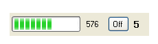
另外,在FirmataVB中,还加入了对数字引脚控制,模拟引脚控制的UI控件,如下图所示:
 |  |
 |
在使用这两个UI控件时,当然只能使用前述的第一种方式,也就是引入ToolBox后,将其拖入界面设计表单中。这两个控件并不向Arduino发送任何命令,只是一些参数的设置,如端口号等!
4. FirmataVB的用法
FirmataVB的用法很简单,先看一下FirmataVB的库结构:

下图为FirmataVB中的方法,每个方法的名称已经可以大致说明该方法的功能,在此只举常用的几个进行说明。
- 1.
public void AnalogPinReport(int pin, int mode)
该方法设置某模拟通道开启或开闭。如:
private void analogx_AnalogOnOff_Changed(int PinNumber, int OnOff)
{
    arduino.AnalogPinReport(PinNumber, OnOff);//analogx是一个AnalogControl控件对象,arduino 是一个Firmata对象
}

下图是FirmataVB所支持的Arduino板子的类型
5、参考
1. Firmata官方网站


 471
471

 被折叠的 条评论
为什么被折叠?
被折叠的 条评论
为什么被折叠?
 到【灌水乐园】发言


