


Table Of Contents
Configuring Flex Links and the MAC Address-Table Move Update Feature
Understanding Flex Links and the MAC Address-Table Move Update
Configuring Flex Links and MAC Address-Table Move Update
Configuring Flex Links and MAC Address-Table Move Update
Configuring the MAC Address-Table Move Update Feature
Monitoring Flex Links and the MAC Address-Table Move Update
Configuring Flex Links and the MAC Address-Table Move Update Feature
This chapter describes how to configure Flex Links, a pair of interfaces on the Catalyst 3550 switch that provide a mutual backup. It also describes how to configure the MAC address-table move update feature, also referred to as the Flex Links bidirectional fast convergence feature. Unless otherwise noted, the term switch refers to a standalone switch.

Note ![]() For complete syntax and usage information for the commands used in this chapter, see the command reference for this release.
For complete syntax and usage information for the commands used in this chapter, see the command reference for this release.
The chapter consists of these sections:
•![]() Understanding Flex Links and the MAC Address-Table Move Update
Understanding Flex Links and the MAC Address-Table Move Update
•![]() Configuring Flex Links and MAC Address-Table Move Update
Configuring Flex Links and MAC Address-Table Move Update
•![]() Monitoring Flex Links and the MAC Address-Table Move Update
Monitoring Flex Links and the MAC Address-Table Move Update
Understanding Flex Links and the MAC Address-Table Move Update
This section contains this information:
•![]() MAC Address-Table Move Update
MAC Address-Table Move Update
Flex Links
Flex Links are a pair of a Layer 2 interfaces (switch ports or port channels) where one interface is configured to act as a backup to the other. The feature provides an alternative solution to the Spanning Tree Protocol (STP). Users can disable STP and still retain basic link redundancy. Flex Links are typically configured in service provider or enterprise networks where customers do not want to run STP on the switch. If the switch is running STP, Flex Links is not necessary because STP already provides link-level redundancy or backup.
You configure Flex Links on one Layer 2 interface (the active link) by assigning another Layer 2 interface as the Flex Link or backup link. The Flex Link can be on the same switch. When one of the links is up and forwarding traffic, the other link is in standby mode, ready to begin forwarding traffic if the other link shuts down. At any given time, only one of the interfaces is in the linkup state and forwarding traffic. If the primary link shuts down, the standby link starts forwarding traffic. When the active link comes back up, it goes into standby mode and does not forward traffic. STP is disabled on Flex Link interfaces.
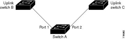
In Figure 18-1, ports 1 and 2 on switch A are connected to uplink switches B and C. Because they are configured as Flex Links, only one of the interfaces is forwarding traffic; the other is in standby mode. If port 1 is the active link, it begins forwarding traffic between port 1 and switch B; the link between port 2 (the backup link) and switch C is not forwarding traffic. If port 1 goes down, port 2 comes up and starts forwarding traffic to switch C. When port 1 comes back up, it goes into standby mode and does not forward traffic; port 2 continues forwarding traffic.
Optionally, you can configure a preemption mechanism, specifying the preferred port for forwarding traffic. For example, you can configure the above flexlink pair with preemption mode so that once port 1 comes back up in the above scenario, if it has greater bandwidth than port 2, port 1 will go forwarding after 60 seconds and port 2 will become standby. This is done by entering the preemption mode bandwidth and delay commands.
Figure 18-1 Flex Links Configuration Example
If a primary (forwarding) link goes down, a trap notifies the network management stations. If the standby link goes down, a trap notifies the users.
Flex Links are supported only on Layer 2 ports and port channels, not on VLANs or on Layer 3 ports.
MAC Address-Table Move Update
The MAC address-table move update feature allows the switch to provide rapid bidirectional convergence when a primary (forwarding) link goes down and the standby link begins forwarding traffic.
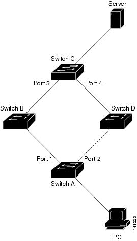
In Figure 18-2, switch A is an access switch, and ports 1 and 2 on switch A are connected to uplink switches B and D through a Flex Link pair. Port 1 is forwarding traffic, and port 2 is in the backup state. Traffic from the PC to the server is forwarded from port 1 to port 3. The MAC address of the PC has been learned on port 3 of switch C. Traffic from the server to the PC is forwarded from port 3 to port 1.
If the MAC address-table move update feature is not configured and port 1 goes down, port 2 starts forwarding traffic. However, for a short time, switch C keeps forwarding traffic from the server to the PC through port 3, and the PC does not get the traffic because port 1 is down. If switch C removes the MAC address of the PC on port 3 and relearns it on port 4, traffic can then be forwarded from the server to the PC through port 2.
If the MAC address-table move update feature is configured and enabled on the switches in Figure 18-2 and port 1 goes down, port 2 starts forwarding traffic from the PC to the server. The switch sends a MAC address-table move update packet from port 2. Switch C gets this packet on port 4 and immediately learns the MAC address of the PC on port 4, which reduces the reconvergence time.
You can configure the access switch, switch A, to send MAC address-table move update messages. You can also configure the uplink switches B, C, and D to get and process the MAC address-table move update messages. When switch C gets a MAC address-table move update message from switch A, switch C learns the MAC address of the PC on port 4. Switch C updates the MAC address table, including the forwarding table entry for the PC. The switch then starts forwarding traffic from the server to the PC through port 4, which reduces the loss of traffic from the server to the PC.
Figure 18-2 MAC Address-Table Move Update Example
Configuring Flex Links and MAC Address-Table Move Update
These sections contain this information:
Configuration Guidelines
Follow these guidelines to configure Flex Links:
•![]() You can configure only one Flex Link backup link for any active link, and it must be a different interface from the active interface.
You can configure only one Flex Link backup link for any active link, and it must be a different interface from the active interface.
•![]() An interface can belong to only one Flex Link pair. An interface can be a backup link for only one active link. An active link cannot belong to another Flex Link pair.
An interface can belong to only one Flex Link pair. An interface can be a backup link for only one active link. An active link cannot belong to another Flex Link pair.
•![]() Neither of the links can be a port that belongs to an EtherChannel. However, you can configure two port channels (EtherChannel logical interfaces) as Flex Links, and you can configure a port channel and a physical interface as Flex Links, with either the port channel or the physical interface as the active link.
Neither of the links can be a port that belongs to an EtherChannel. However, you can configure two port channels (EtherChannel logical interfaces) as Flex Links, and you can configure a port channel and a physical interface as Flex Links, with either the port channel or the physical interface as the active link.
•![]() A backup link does not have to be the same type (Fast Ethernet, Gigabit Ethernet, or port channel) as the active link. However, you should configure both Flex Links with similar characteristics so that there are no loops or changes in behavior if the standby link begins to forward traffic.
A backup link does not have to be the same type (Fast Ethernet, Gigabit Ethernet, or port channel) as the active link. However, you should configure both Flex Links with similar characteristics so that there are no loops or changes in behavior if the standby link begins to forward traffic.
•![]() STP is disabled on Flex Link ports. A Flex Link port does not participate in STP, even if the VLANs present on the port are configured for STP. When STP is not enabled, be sure that there are no loops in the configured topology.
STP is disabled on Flex Link ports. A Flex Link port does not participate in STP, even if the VLANs present on the port are configured for STP. When STP is not enabled, be sure that there are no loops in the configured topology.
Follow these guidelines to configure MAC address-table move update feature:
•![]() You can enable and configure this feature on the access switch to send the MAC address-table move updates.
You can enable and configure this feature on the access switch to send the MAC address-table move updates.
•![]() You can enable and configure this feature on the uplink switches to get the MAC address-table move updates.
You can enable and configure this feature on the uplink switches to get the MAC address-table move updates.
Default Configuration
The Flex Links are not configured, and there are no backup interfaces defined.
The preemption mode is OFF.
The preemption delay is 35 seconds.
The MAC address-table move update feature is not configured on the switch.
Configuring Flex Links and MAC Address-Table Move Update
This section contains this information:
•![]() Configuring the MAC Address-Table Move Update Feature
Configuring the MAC Address-Table Move Update Feature
Configuring Flex Links
Beginning in privileged EXEC mode, follow these steps to configure a pair of Flex Links:
This example shows how to configure an interface with a backup interface and to verify the configuration:
Switch# configure terminal
Switch(conf)# interface gigabitethernet0/21
Switch(conf-if)# switchport backup interface gigabitethernet0/22
Switch(conf-if)# end
Switch# show interface switchport backup
Switch Backup Interface Pairs:
Active Interface Backup Interface State
------------------------------------------------------------------------------------------
FastEthernet1/0/1 FastEthernet1/0/2 Active Up/Backup Standby
FastEthernet1/0/3 FastEthernet2/0/4 Active Up/Backup Standby
Port-channel1 GigabitEthernet7/0/1 Active Up/Backup Standby
GigabitEthernet0/21 GigabitEthernet0/22 Active Up/Backup Standby
GigabitEthernet0/3 GigabitEthernet0/4 Active Up/Backup Standby
Port-channel1 GigabitEthernet0/5 Active Up/Backup Standby
Beginning in Interface Configuration mode, follow these steps to configure a preemption scheme for a pair of Flex Links:
This example shows how to configure preemption mode as bandwidth, for a backup interface pair and to verify the configuration:
Switch# configure terminal
Switch(conf)# interface gigabitethernet0/1
Switch(conf-if)#switchport backup interface gigabitethernet0/2 preemption mode forced
Switch(conf-if)#switchport backup interface gigabitethernet0/2 preemption delay 50
Switch(conf-if)# end
Switch# show interface switchport backup detail
Active Interface Backup Interface State
------------------------------------------------------------------------
GigabitEthernet0/21 GigabitEthernet0/2 Active Up/Backup Standby
Interface Pair : Gi0/1, Gi0/2
Preemption Mode : forced
Preemption Delay : 50 seconds
Bandwidth : 100000 Kbit (Gi0/1), 100000 Kbit (Gi0/2)
Mac Address Move Update Vlan : auto
Configuring the MAC Address-Table Move Update Feature
This section contains this information:
•![]() Configuring a switch to send MAC address-table move updates
Configuring a switch to send MAC address-table move updates
•![]() Configuring a switch to get MAC address-table move updates
Configuring a switch to get MAC address-table move updates
Beginning in privileged EXEC mode, follow these steps to configure an access switch to send MAC address-table move updates:
To disable the MAC address-table move update feature on the access switch, use the no mac address-table move update transmit interface configuration command. To display the MAC address-table move update information, use the show mac address-table move update privileged EXEC command.
This example shows how to configure an access switch to send MAC address-table move update messages:
Switch# configure terminal
Switch(conf)# interface gigabitethernet0/21
Switch(conf-if)# switchport backup interface fastethernet1/0/2
Switch(conf-if)# switchport backup interface gigabitethernet0/22 mmu primary vlan 2
Switch(conf-if)# end
Switch(conf)# mac address-table move update transmit
Switch(conf)# end
Verify the configuration as shown in the following example:
Switch# show mac-address-table move update
Switch-ID : 01d0.2bfc.3180
Dst mac-address : 0180.c200.0010
Vlans/Macs supported : 1023/8320
Default/Current settings: Rcv Off/Off, Xmt Off/Off
Max packets per min : Rcv 40, Xmt 60
Rcv packet count : 0
Rcv conforming packet count : 0
Rcv invalid packet count : 0
Rcv packet count this min : 0
Rcv threshold exceed count : 0
Rcv last sequence# this min : 0
Rcv last interface : None
Rcv last src-mac-address : 0000.0000.0000
Rcv last switch-ID : 0000.0000.0000
Xmt packet count : 0
Xmt packet count this min : 0
Xmt threshold exceed count : 0
Xmt pak buf unavail cnt : 0
Xmt last interface : None
Beginning in privileged EXEC mode, follow these steps to configure a switch to get and process MAC address-table move update messages:
To disable the MAC address-table move update feature on the access switch, use the no mac address-table move update receive configuration command. To display the MAC address-table move update information, use the show mac address-table move update privileged EXEC command.
This example shows how to configure a switch to get and process MAC address-table move update messages:
Switch# configure terminal
Switch(conf)# mac address-table move update receive
Switch(conf)# end
Monitoring Flex Links and the MAC Address-Table Move Update
Table 18-1 shows the privileged EXEC commands for monitoring the Flex Links configuration and the MAC address-table move update information.


 被折叠的 条评论
为什么被折叠?
被折叠的 条评论
为什么被折叠?
 到【灌水乐园】发言


