


在信道的通信过程中由于噪声等因素难免会引起信道中所传输的数据出错,循环冗余校验 ( C R C , c y c l i c r e d u n d a n c y c h e c k ) (CRC,cyclic\quad redundancy\quad check) (CRC,cyclicredundancycheck)就是为了在接收方检验所接收的数据是否有错以及进行进一步纠错的一种方法。例如 S T M 32 F 103 STM32F103 STM32F103芯片的 I 2 C I^2C I2C模块里的 P E C PEC PEC功能其实就是采用循环冗余校验来实现在接收方的通信错误判断功能,如图1所示。

其实循环冗余校验的流程还是比较简单的,如图2所示。就是 T R A N S M I T T E R TRANSMITTER TRANSMITTER在发送数据之前在原始要发送的数据的后面加上 C R C C o d e CRC\quad Code CRCCode,然后将组合之后的数据一起发送出去。 R E C E I V E R RECEIVER RECEIVER在接收到数据之后通过一定的方式检验收到的数据是否有错误,如果没有错误就就收,如果有错误就丢弃并进行一定的纠错机制,比如要求 T R A N S M I T T E R TRANSMITTER TRANSMITTER重新发送刚才的数据。

现在的问题是
C
R
C
C
o
d
e
CRC\quad Code
CRCCode如何计算,以及
R
E
C
E
I
V
E
R
RECEIVER
RECEIVER在接收到数据之后如何检验收到的数据是否有错误?因为
C
R
C
C
o
d
e
CRC\quad Code
CRCCode的计算和多项式长除法或一般的长除法类似,因此我们先简单的看一下多项式长除法或一般的长除法,其思想简单说明就是将多数位的除法转换为许多简单的除法步骤以化解难度,至于多项式长除法和一般的长除法的原理解释请看前面的维基百科链接:(Polynomial long division Long division)。
我们先来看一个简单的整数的长除法的例子
1260527
÷
37
=
34061
1260527\div37=34061
1260527÷37=34061,如图3所示。具体的原理去看维基百科,其实最简单明了的解释就是:
- 30000 × 37 = 1110000 30000\times37=1110000 30000×37=1110000
- 4000 × 37 = 148000 4000\times37 =148000 4000×37=148000
- 0 × 100 × 37 = 0 0\times100\times37=0 0×100×37=0
- 60 × 37 = 2220 60\times37=2220 60×37=2220
- 1 × 37 = 37 1\times37=37 1×37=37
- 1110000 + 148000 + 2220 + 37 = 1258000 + 2257 = 1260257 1110000+148000+2220+37=1258000+2257=1260257 1110000+148000+2220+37=1258000+2257=1260257

我们再来看一个简单的多项式长除法的例子 x 3 − 4 x 2 + 2 x − 3 x + 2 = x 2 − 6 x + 14 − 31 x + 2 \frac{x^3-4x^2+2x-3}{x+2}=x^2-6x+14-\frac{31}{x+2} x+2x3−4x2+2x−3=x2−6x+14−x+231,如图4所示。具体的原理去看维基百科,其实最简单明了的解释就是:
- x 2 × ( x + 2 ) = x 3 + 2 x 2 x^2\times(x+2)=x^3+2x^2 x2×(x+2)=x3+2x2
- − 6 x × ( x + 2 ) = − 6 x 2 − 12 x -6x\times(x+2)=-6x^2-12x −6x×(x+2)=−6x2−12x
- 14 × ( x + 2 ) = 14 x + 28 14\times(x+2)=14x+28 14×(x+2)=14x+28
- 除法的余数为 − 31 除法的余数为-31 除法的余数为−31
- x 3 + 2 x 2 − 6 x 2 − 12 x + 14 x + 28 − 31 = x 3 − 4 x 2 − 2 x + 3 x^3+2x^2-6x^2-12x+14x+28-31=x^3-4x^2-2x+3 x3+2x2−6x2−12x+14x+28−31=x3−4x2−2x+3

一般如果准备在通信过程中加入
C
R
C
C
o
d
e
CRC\quad Code
CRCCode,那么肯定首先会确定一个发生器多项式(generator polynomial),这个发生器多项式会用来计算
C
R
C
C
o
d
e
CRC\quad Code
CRCCode并确定了
C
R
C
C
o
d
e
CRC\quad Code
CRCCode的长度。如图1所示的
I
2
C
I^2C
I2C模块的PEC功能使用的发生器多项式为
x
8
+
x
2
+
x
+
1
x^8+x^2+x+1
x8+x2+x+1,发生器多项式的最高次幂为
C
R
C
C
o
d
e
CRC\quad Code
CRCCode的长度,也就是
C
R
C
C
o
d
e
CRC\quad Code
CRCCode的二进制位的个数。发生器多项式的每一项的系数要么为0,要么为1。
如果现在有了k个二进制位的
O
r
i
g
i
n
a
l
D
a
t
a
=
[
m
k
−
1
,
m
k
−
2
.
.
.
,
m
1
,
m
0
]
Original\quad Data=[m_{k-1},m_{k-2}...,m_1,m_0]
OriginalData=[mk−1,mk−2...,m1,m0]和最高次幂为n的发生器多项式为
g
(
x
)
=
r
n
x
n
+
r
n
−
1
x
n
−
1
+
.
.
.
+
r
1
x
+
r
0
g(x)=r_{n}x^n+r_{n-1}x^{n-1}+...+r_1x+r_0
g(x)=rnxn+rn−1xn−1+...+r1x+r0。为了计算
C
R
C
C
o
d
e
CRC\quad Code
CRCCode,我们现将
O
r
i
g
i
n
a
l
D
a
t
a
=
[
m
k
−
1
,
m
k
−
2
.
.
.
,
m
1
,
m
0
]
Original\quad Data=[m_{k-1},m_{k-2}...,m_1,m_0]
OriginalData=[mk−1,mk−2...,m1,m0]转换为和发生器多项式一样的形式
m
(
x
)
m(x)
m(x)=
m
k
−
1
x
k
−
1
+
m
k
−
2
x
k
−
2
+
.
.
.
m
1
x
+
m
0
m_{k-1}x^{k-1}+m_{k-2}x^{k-2}+...m_1x+m_0
mk−1xk−1+mk−2xk−2+...m1x+m0,然后将得到的这个对应
O
r
i
g
i
n
a
l
D
a
t
a
Original\quad Data
OriginalData的多项式乘上
x
n
x^n
xn得到多项式
m
k
−
1
x
n
+
k
−
1
+
m
k
−
2
x
n
+
k
−
2
+
.
.
.
m
1
x
n
+
1
+
m
0
x
n
m_{k-1}x^{n+k-1}+m_{k-2}x^{n+k-2}+...m_1x^{n+1}+m_0x^n
mk−1xn+k−1+mk−2xn+k−2+...m1xn+1+m0xn=
x
n
m
(
x
)
x^nm(x)
xnm(x)。这里
m
i
,
i
=
0
,
1
,
.
.
.
,
k
−
1
m_i,i=0,1,...,k-1
mi,i=0,1,...,k−1和
r
j
,
j
=
0
,
1
,
.
.
.
,
n
r_j,j=0,1,...,n
rj,j=0,1,...,n要么为0,要么为1。
如果现在我们用多项式
g
(
x
)
g(x)
g(x)去除多项式
x
n
m
(
x
)
x^nm(x)
xnm(x)得到
x
n
m
(
x
)
x^nm(x)
xnm(x)=
p
(
x
)
g
(
x
)
+
r
(
x
)
p(x)g(x)+r(x)
p(x)g(x)+r(x),其中
p
(
x
)
p(x)
p(x)除得的商多项式,
r
(
x
)
r(x)
r(x)为余数多项式(其最高次幂为
n
−
1
n-1
n−1)。多项式
p
(
x
)
p(x)
p(x)和
r
(
x
)
r(x)
r(x)唯一(至于理论自己去找一下资料,这里我也不是完全懂)。多项式
r
(
x
)
=
c
n
−
1
x
n
−
1
+
c
n
−
2
x
n
−
2
+
.
.
.
c
1
x
+
c
0
r(x)=c_{n-1}x^{n-1}+c_{n-2}x^{n-2}+...c_1x+c_0
r(x)=cn−1xn−1+cn−2xn−2+...c1x+c0的n的系数
[
c
n
−
1
,
c
n
−
2
.
.
.
,
c
1
,
c
0
]
[c_{n-1},c_{n-2}...,c_1,c_0]
[cn−1,cn−2...,c1,c0]即为计算得到的
C
R
C
C
o
d
e
CRC\quad Code
CRCCode。
注意这里的多项式除法和前面给出的多项式除法的例子的运算过程类似,不同的是这里的多项式的系数只能是0和1,且对幂次相同的项之间的加减采用模2运算,如下所示:
- 0 x 2 ± 0 x 2 = 0 x 2 = 0 0x^2\pm0x^2=0x^2=0 0x2±0x2=0x2=0
- 0 x 2 ± x 2 = x 2 0x^2\pm x^2=x^2 0x2±x2=x2
- x 2 ± 0 x 2 = x 2 x^2\pm0x^2=x^2 x2±0x2=x2
- x 2 ± x 2 = 0 x 2 = 0 x^2\pm x^2=0x^2=0 x2±x2=0x2=0
根据上面的推导,我们在接收方接收到的包含
C
R
C
C
o
d
e
CRC\quad Code
CRCCode的数据对应的多项式为
x
n
m
(
x
)
+
r
(
x
)
x^nm(x)+r(x)
xnm(x)+r(x),我们用接收方接收到的包含
C
R
C
C
o
d
e
CRC\quad Code
CRCCode的数据对应的多项式去除以发生器多项式
x
n
m
(
x
)
+
r
(
x
)
g
(
x
)
\frac{x^nm(x)+r(x)}{g(x)}
g(x)xnm(x)+r(x),因为我们已经求得
x
n
m
(
x
)
x^nm(x)
xnm(x)=
p
(
x
)
g
(
x
)
+
r
(
x
)
p(x)g(x)+r(x)
p(x)g(x)+r(x),所以:
x
n
m
(
x
)
+
r
(
x
)
g
(
x
)
=
p
(
x
)
g
(
x
)
+
2
r
(
x
)
g
(
x
)
\frac{x^nm(x)+r(x)}{g(x)}=\frac{p(x)g(x)+2r(x)}{g(x)}
g(x)xnm(x)+r(x)=g(x)p(x)g(x)+2r(x)。又因为按照以上介绍的多项式的模2运算,
2
r
(
x
)
=
0
2r(x)=0
2r(x)=0。因此
x
n
m
(
x
)
+
r
(
x
)
g
(
x
)
=
p
(
x
)
g
(
x
)
+
2
r
(
x
)
g
(
x
)
=
p
(
x
)
\frac{x^nm(x)+r(x)}{g(x)}=\frac{p(x)g(x)+2r(x)}{g(x)}=p(x)
g(x)xnm(x)+r(x)=g(x)p(x)g(x)+2r(x)=p(x)。这也就是说如果在接收方接收到的数据如果没有错的话,以上多项式的除法的余数多项式应该为0,这也就是检验接收到的数据是否有错的方法。
下面我们来举一个具体的例子。假设现在我们要发送的
O
r
i
g
i
n
a
l
D
a
t
a
=
[
m
k
−
1
,
m
k
−
2
.
.
.
,
m
1
,
m
0
]
=
[
1
,
1
,
1
,
0
,
0
,
1
,
1
,
0
]
Original\quad Data=[m_{k-1},m_{k-2}...,m_1,m_0]=[1,1,1,0,0,1,1,0]
OriginalData=[mk−1,mk−2...,m1,m0]=[1,1,1,0,0,1,1,0],发生器多项式为
g
(
x
)
=
x
4
+
x
3
+
1
g(x)=x^4+x^3+1
g(x)=x4+x3+1,
C
R
C
C
o
d
e
CRC\quad Code
CRCCode的比特个数为4。因此
m
(
x
)
m(x)
m(x)=
x
7
+
x
6
+
x
5
+
x
2
+
x
x^{7}+x^{6}+x^{5}+x^2+x
x7+x6+x5+x2+x,
x
n
m
(
x
)
=
x
11
+
x
10
+
x
9
+
x
6
+
x
5
x^nm(x)=x^{11}+x^{10}+x^{9}+x^6+x^5
xnm(x)=x11+x10+x9+x6+x5。此时求
C
R
C
C
o
d
e
CRC\quad Code
CRCCode的余数多项式的过程如图5所示。求得的余数多项式为
r
(
x
)
r(x)
r(x)=
x
2
+
x
x^2+x
x2+x,因此
C
R
C
C
o
d
e
=
[
0
,
1
,
1
,
0
]
CRC\quad Code=[0,1,1,0]
CRCCode=[0,1,1,0]。那么发送给接收方的数据就是
[
1
,
1
,
1
,
0
,
0
,
1
,
1
,
0
,
0
,
1
,
1
,
0
]
[1,1,1,0,0,1,1,0,\quad0,1,1,0]
[1,1,1,0,0,1,1,0,0,1,1,0]。即
x
n
m
(
x
)
+
r
(
x
)
=
x
11
+
x
10
+
x
9
+
x
6
+
x
5
+
x
2
+
x
x^nm(x)+r(x)=x^{11}+x^{10}+x^{9}+x^6+x^5+x^2+x
xnm(x)+r(x)=x11+x10+x9+x6+x5+x2+x

下面我们验证一下 g ( x ) = x 4 + x 3 + 1 g(x)=x^4+x^3+1 g(x)=x4+x3+1除以 x n m ( x ) + r ( x ) x^nm(x)+r(x) xnm(x)+r(x)的余数多项式是否为0。运算过程如图6所示。验证通过。

发生器多项式是根据实际情况的需要选择的,不同的发生器多项式对传输错误的检测能力也不一样,这里也是学问,有需要的自己去研究研究。我们现在已经知道了 C R C C o d e CRC\quad Code CRCCode如何计算以及收到带 C R C C o d e CRC\quad Code CRCCode的数据之后如何验证其正确性。那么我们应该如何用计算机代码实现它们。对于图5和图6的计算 C R C C o d e CRC\quad Code CRCCode以及检验数据正确与否的多项式除法过程我们也可以用文章开头提到的类似整数的长除法的形式展现出来,分别如图7和图8所示。只不过这里除数和被除数都是对应的多项式的系数组成的二进制串,且每一次的运算都是上下对应的比特位之间的模2减法运算,不存在进位。其实也就是二进制的异或运算。对,计算机代码在实现时就是这样操作的。对于多项式 x n m ( x ) x^nm(x) xnm(x)和 x n m ( x ) + r ( x ) x^nm(x)+r(x) xnm(x)+r(x),计算其对应的 C R C C o d e CRC\quad Code CRCCode和验证数据正确与否的过程都是先将其所有系数组合成对应的二进制串和发生器多项式对应的二进制串的高位一一对应起来,然后将多项式 x n m ( x ) x^nm(x) xnm(x)和 x n m ( x ) + r ( x ) x^nm(x)+r(x) xnm(x)+r(x)的二进制串中和发生器的二进制串的n个比特对应的两个比特位做异或运算,然后将运算的结果替代多项式 x n m ( x ) x^nm(x) xnm(x)和 x n m ( x ) + r ( x ) x^nm(x)+r(x) xnm(x)+r(x)的二进制串中原有位置的二进制位,接下来从左到右找到上一步得到的多项式 x n m ( x ) x^nm(x) xnm(x)和 x n m ( x ) + r ( x ) x^nm(x)+r(x) xnm(x)+r(x)的二进制串中第一个不为0的比特位并从这位开始将发生器的二进制串的所有比特位从高位开始一一对齐并重复以上运算直到得到的多项式 x n m ( x ) x^nm(x) xnm(x)和 x n m ( x ) + r ( x ) x^nm(x)+r(x) xnm(x)+r(x)的二进制串中全部为0值的二进制位或者剩余的从最高位的不为0的比特位算起的比特位的个数小于发生器多项式的最高次幂数。


下面我将贴出实际的计算 C R C C o d e CRC\quad Code CRCCode的c语言代码。 这里我说一下,我这篇文章只能是一个概括性的一般介绍,其实我发现如果要细究的话, C R C C o d e CRC\quad Code CRCCode涉及到的东西还是很多的,我也发现了两篇不错的参考文档,如果你想对这方面有深入了解的话,可以花时间好好看看这两篇文章:
- Understanding and implementing CRC (Cyclic Redundancy Check) calculation
- A PAINLESS GUIDE TO CRC ERROR DETECTION ALGORITHMS
资源2网络上应该比较好找,我怕资源1失效,所以我存了一份在这里,有需要的可以下载。我下面贴出的代码都是参考于资源1,只不过他是用
C
#
C\#
C#写的,我改成C语言的。下面的代码都是基于
C
R
C
8
CRC8
CRC8的(扩展到其它类型的多项式也是很容易的),也就是发生器多项式的最高次幂为8,且最高次幂为8的项的系数必须为1,这对其它类型的发生器多项式,比如
C
R
C
16
CRC16
CRC16、
C
R
C
32
CRC32
CRC32都是一样的,一般情况下0次幂的项的系数也为1。
还有一点要说明一下,上面也提到的,如果选择
C
R
C
8
CRC8
CRC8类型的发生器多项式的话,比如
g
(
x
)
=
x
8
+
x
4
+
x
3
+
x
2
+
1
g(x)=x^8+x^4+x^3+x^2+1
g(x)=x8+x4+x3+x2+1,参与运算的对应发生器多项式的比特流是9个比特位,而不是8个比特位,这点要注意一下。但是我们可能会想,计算机一般运算的单位都是字节(8个比特)或其倍数。这样9个比特位会不会比较麻烦,其实这里有一个下面的代码中也会用到的技巧。从图7和图8中我们可以看到在实际的运算时,都当从高位到低位从左到右找到
O
r
i
g
i
n
a
l
D
a
t
a
Original\quad Data
OriginalData(尾部已经添加对应的比特0位)或接收到的包含
C
R
C
C
o
d
e
CRC\quad Code
CRCCode的数据中的第一个为1的比特位时,我们会从该位开始将发生器多项式的比特流和其对应然后进行亦或运算。其实我们可以发现发生器多项式的比特流的最高位其实是可以不参与异或运算的,因为每次异或运算的结果都是0,且异或完成之后
O
r
i
g
i
n
a
l
D
a
t
a
Original\quad Data
OriginalData或接收到的包含
C
R
C
C
o
d
e
CRC\quad Code
CRCCode的数据中的该位以后都不会参与运算了,因为整个发生器多项式的比特流会向右移动,因为我们求的是
C
R
C
C
o
d
e
CRC\quad Code
CRCCode,也就是余数,所以在以下的代码中参与运算的发生器多项式的比特流只有低8位(
C
R
C
8
CRC8
CRC8类型)。当从高位到低位从左到右找到
O
r
i
g
i
n
a
l
D
a
t
a
Original\quad Data
OriginalData(尾部已经添加对应的比特0位)或接收到的包含
C
R
C
C
o
d
e
CRC\quad Code
CRCCode的数据中的第一个为1的比特位时,我们会从该位开始将发生器多项式的比特流和其对应然后低8位进行亦或运算。最高位在代码中被移出去了,所以也不影响。
下面的代码先从要计算
C
R
C
C
o
d
e
CRC\quad Code
CRCCode的数据为一个字节的数据
0
x
C
2
=
11000010
0xC2=11000010
0xC2=11000010开始,发生器多项式为
g
(
x
)
=
x
8
+
x
4
+
x
3
+
x
2
+
1
(
1
0001
1101
)
g(x)=x^8+x^4+x^3+x^2+1(1\quad 0001\quad 1101)
g(x)=x8+x4+x3+x2+1(100011101),其具体计算过程详见图9。函数
C
o
m
p
u
t
e
_
O
n
e
_
B
y
t
e
_
D
a
t
a
_
c
r
c
_
R
e
m
a
i
n
d
e
r
8
Compute\_One\_Byte\_Data\_crc\_Remainder8
Compute_One_Byte_Data_crc_Remainder8给出了当要计算
C
R
C
C
o
d
e
CRC\quad Code
CRCCode的原始数据为1个字节的时候的计算代码。
C
o
m
p
u
t
e
_
M
u
l
t
i
_
B
y
t
e
_
D
a
t
a
_
c
r
c
_
R
e
m
a
i
n
d
e
r
8
Compute\_Multi\_Byte\_Data\_crc\_Remainder8
Compute_Multi_Byte_Data_crc_Remainder8给出了当要计算
C
R
C
C
o
d
e
CRC\quad Code
CRCCode的原始数据有多个字节的时候的计算代码,其参数数组
b
y
t
e
A
r
r
a
y
byteArray
byteArray已经附加了要附加的8个比特0位,参数
b
y
t
e
A
r
r
a
y
L
e
n
g
t
h
byteArrayLength
byteArrayLength为附加了8个比特0位的数组的长度。这里的代码可以说是完全实现了前面介绍的
C
R
C
C
o
d
e
CRC\quad Code
CRCCode计算过程,代码里面的以下两句代码实现了移位和对齐功能。
crc_Remainder = (uint8_t)(crc_Remainder << 1);
crc_Remainder = ((uint8_t)(next_Inputstream_Byte & (1 << bit_index)) != 0) ? (uint8_t)(crc_Remainder | 0x01) : (uint8_t)(crc_Remainder & 0xFE);

static uint8_t Compute_One_Byte_Data_crc_Remainder8(uint8_t byteVal)
{
    int bit_index=0;
    uint8_t generator_Polynomial = 0x1D;
    uint8_t crc_Remainder = byteVal; /* initialize crc remainder with byteVal */
    /* Append 8 zero bits to the input stream */
    uint8_t inputstream[2] = { byteVal, 0x00 };
    uint8_t next_Inputstream_Byte = inputstream[1];
    /* Handle each bit of input stream by iterating over each bit of next_Inputstream_Byte */
    for (bit_index = 7; bit_index >= 0; bit_index--)
    {
        /* check if MSB is set */
        if ((crc_Remainder & 0x80) != 0)
        {
            /* MSB set, shift it out of the crc_Remainder */
            crc_Remainder = (uint8_t)(crc_Remainder << 1);
            /* shift in next bit of input stream:
             * If it's 1, set LSB of crc_Remainder to 1.
             * If it's 0, set LSB of crc_Remainder to 0. */
            crc_Remainder = ((uint8_t)(next_Inputstream_Byte & (1 << bit_index)) != 0) ? (uint8_t)(crc_Remainder | 0x01) : (uint8_t)(crc_Remainder & 0xFE);
            /* Perform the 'division' by XORing the crc_Remainder with the generator polynomial */
            crc_Remainder = (uint8_t)(crc_Remainder ^ generator_Polynomial);
        }
        else
        {
            /* MSB not set, shift it out and shift in next bit of input stream. Same as above, just no division */
            crc_Remainder = (uint8_t)(crc_Remainder << 1);
            crc_Remainder = ((uint8_t)(next_Inputstream_Byte & (1 << bit_index)) != 0) ? (uint8_t)(crc_Remainder | 0x01) : (uint8_t)(crc_Remainder & 0xFE);
        }
    }
    return crc_Remainder;
}
uint8_t Compute_Multi_Byte_Data_crc_Remainder8(uint8_t* byteArray,uint32_t byteArrayLength)
{
    int     bit_index=0;
    uint32_t byte_index=0;
    uint8_t generator_Polynomial = 0x1D;
    uint8_t crc_Remainder = byteArray[0]; /* initialize crc remainder with first byte in the byteArray */
    /* Note:The 8 zero bits has been appended to the byte array in the byte byteArray[byteArrayLength-1] */
    uint8_t next_Inputstream_Byte = 0;
    /* Handle each bit of input stream by iterating over each bit of each input byte next_Inputstream_Byte*/
    for (byte_index=0; byte_index <(byteArrayLength-1); byte_index++)
    {
        next_Inputstream_Byte=byteArray[byte_index+1];
        for (bit_index = 7; bit_index >= 0; bit_index--)
        {
            /* check if MSB is set */
            if ((crc_Remainder & 0x80) != 0)
            {
                /* MSB set, shift it out of the crc_Remainder */
                crc_Remainder = (uint8_t)(crc_Remainder << 1);
                /* shift in next bit of input stream:
                 * If it's 1, set LSB of crc_Remainder to 1.
                 * If it's 0, set LSB of crc_Remainder to 0. */
                crc_Remainder = ((uint8_t)(next_Inputstream_Byte & (1 << bit_index)) != 0) ? (uint8_t)(crc_Remainder | 0x01) : (uint8_t)(crc_Remainder & 0xFE);
                /* Perform the 'division' by XORing the crc_Remainder with the generator polynomial */
                crc_Remainder = (uint8_t)(crc_Remainder ^ generator_Polynomial);
            }
            else
            {
                /* MSB not set, shift it out and shift in next bit of input stream. Same as above, just no division */
                crc_Remainder = (uint8_t)(crc_Remainder << 1);
                crc_Remainder = ((uint8_t)(next_Inputstream_Byte & (1 << bit_index)) != 0) ? (uint8_t)(crc_Remainder | 0x01) : (uint8_t)(crc_Remainder & 0xFE);
            }
        }
    }
    return crc_Remainder;
}
前面的代码实现的效率有那么一点低,
C
o
m
p
u
t
e
_
M
u
l
t
i
_
B
y
t
e
_
D
a
t
a
_
c
r
c
_
R
e
m
a
i
n
d
e
r
8
_
P
r
o
Compute\_Multi\_Byte\_Data\_crc\_Remainder8\_Pro
Compute_Multi_Byte_Data_crc_Remainder8_Pro对前面的代码实现进行了一些改进,效率会更高一点。这里的实现与前面的明显区别是内循环中只处理当前的
B
y
t
e
Byte
Byte并没有将下一个输入数据流的
B
y
t
e
Byte
Byte移入
c
r
c
_
R
e
m
a
i
n
d
e
r
crc\_Remainder
crc_Remainder,这也让程序的处理流程似乎和前面介绍的
C
R
C
C
o
d
e
CRC\quad Code
CRCCode计算流程有些不一样,但是程序中多了一个语句crc_Remainder=crc_Remainder ^ byteArray[byte_index]; 该语句让整个代码流程和前面介绍的
C
R
C
C
o
d
e
CRC\quad Code
CRCCode计算流程一样。但是这里理解起来有一些困难,我当初也是卡在这里。下面我将重点讲一下。
uint8_t Compute_Multi_Byte_Data_crc_Remainder8_Pro(uint8_t* byteArray,uint32_t byteArrayLength)
{
    int     bit_index=0;
    uint32_t byte_index=0;
    uint8_t generator_Polynomial = 0x1D;
    uint8_t crc_Remainder = 0; /* Initialize crc remainder with zero byte. */
    /* Note:The 8 zero bits has been appended to the byte array in the byte byteArray[byteArrayLength-1] */
    /* Handle each byte of input stream*/
    for (byte_index=0; byte_index <(byteArrayLength-1); byte_index++)
    {
        crc_Remainder=crc_Remainder ^ byteArray[byte_index];
        for (bit_index = 0; bit_index <8; bit_index++)
        {
            /* check if MSB is set */
            if ((crc_Remainder & 0x80) != 0)
            {
                /* MSB set, shift it out of the crc_Remainder and shift in next bit of zero bit.*/
                crc_Remainder = (uint8_t)(crc_Remainder << 1);
                /* Perform the 'division' by XORing the crc_Remainder with the generator polynomial */
                crc_Remainder = (uint8_t)(crc_Remainder ^ generator_Polynomial);
            }
            else
            {
                /* MSB not set, shift it out and shift in next bit of zero bit. Same as above, just no division */
                crc_Remainder = (uint8_t)(crc_Remainder << 1);
            }
        }
    }
    return crc_Remainder;
}
假设我们现在要计算
M
e
a
s
s
g
e
=
0
x
21
,
0
x
92
Meassge={0x21,0x92}
Meassge=0x21,0x92的
C
R
C
C
o
d
e
CRC\quad Code
CRCCode,我们在处理
M
e
a
s
s
g
e
=
0
x
21
,
0
x
92
Meassge={0x21,0x92}
Meassge=0x21,0x92的第一个数据字节
0
x
21
0x21
0x21的时候普通算法和改进算法的流程分别如图10、11所示。从图10和图11中我们可以看到,在处理第一个数据字节
0
x
21
0x21
0x21的时候只需要两次异或运算就可以了(
D
a
t
a
b
y
t
e
o
n
e
Data\quad byte\quad one
Databyteone中的所有比特位都已经为0)。在普通算法中,在两次异或运算第二个数据字节
0
x
92
0x92
0x92的部分比特位也参与了运算,相当于操作
(
D
a
t
a
b
y
t
e
t
w
o
)
X
O
R
(
b
10100000
)
X
O
R
(
b
00111010
)
=
(
D
a
t
a
b
y
t
e
t
w
o
)
X
O
R
(
b
10011010
)
(Data\quad byte\quad two)\quad XOR\quad(b10100000)\quad XOR\quad (b00111010)=(Data\quad byte\quad two)\quad XOR\quad(b10011010)
(Databytetwo)XOR(b10100000)XOR(b00111010)=(Databytetwo)XOR(b10011010),因此当第一个数据字节处理完之后
c
r
c
_
R
e
m
a
i
n
d
e
r
crc\_Remainder
crc_Remainder里面就是
(
D
a
t
a
b
y
t
e
t
w
o
)
X
O
R
(
b
10011010
)
(Data\quad byte\quad two)\quad XOR\quad(b10011010)
(Databytetwo)XOR(b10011010),如图10所示。。但是对于改进算法因为在内循环中只处理当前的
B
y
t
e
Byte
Byte并没有将下一个输入数据流的
B
y
t
e
Byte
Byte移入
c
r
c
_
R
e
m
a
i
n
d
e
r
crc\_Remainder
crc_Remainder,因此当第一个数据字节处理完之后
c
r
c
_
R
e
m
a
i
n
d
e
r
crc\_Remainder
crc_Remainder里面就是
b
10011010
b10011010
b10011010,如图11所示。因此在改进算法中在进入内循环之前会有语句crc_Remainder=crc_Remainder ^ byteArray[byte_index]; 调用。图13是在
K
E
I
L
KEIL
KEIL环境下的测试结果。


其实以上的方法在数据量过大的时候,效率还是比较低,因此有了下面的查表算法。从图10和图11我们可以知道上面的改进算法在计算的时候每次内循环中只处理当前的 B y t e Byte Byte并没有将下一个输入数据流的 B y t e Byte Byte移入 c r c _ R e m a i n d e r crc\_Remainder crc_Remainder,这里就相当于每次计算一个 B y t e Byte Byte的 C R C C o d e CRC\quad Code CRCCode, 在计算完当前的 B y t e Byte Byte之后再进行异或运算。这里的一个 B y t e Byte Byte的所有可能值是有限的,在发生器多项式确定的情况下,查表算法的思想是先将一个 B y t e Byte Byte的所有可能值的 C R C C o d e CRC\quad Code CRCCode全部计算出来,需要的时候去查表就可以,避免了重复的计算,加快了速度。实现代码如下所示。图13是在 K E I L KEIL KEIL环境下的测试结果。
void Compute_crc8_Table(uint8_t* crc8_table)
{
    int     bit_index=0;
    uint32_t divident_index=0;
    uint8_t generator_Polynomial = 0x1D;
    uint8_t crc_Remainder = 0; /* Initialize crc remainder with zero byte. */
    for (divident_index=0; divident_index <256; divident++)
    {
        crc_Remainder=divident_index;
        for (bit_index = 0; bit_index < 8; bit_index++)
        {
            /* check if MSB is set */
            if ((crc_Remainder & 0x80) != 0)
            {
                /* MSB set, shift it out of the crc_Remainder and shift in next bit of zero bit.*/
                crc_Remainder = (uint8_t)(crc_Remainder << 1);
                /* Perform the 'division' by XORing the crc_Remainder with the generator polynomial */
                crc_Remainder = (uint8_t)(crc_Remainder ^ generator_Polynomial);
            }
            else
            {
                /* MSB not set, shift it out and shift in next bit of zero bit. Same as above, just no division */
                crc_Remainder = (uint8_t)(crc_Remainder << 1);
            }
        }
        crc8_table[divident_index]=crc_Remainder;
    }
    return;
}


uint8_t Compute_Multi_Byte_Data_crc_Remainder8_Table(uint8_t* byteArray,uint32_t byteArrayLength,uint8_t* crc8_table)
{
    uint32_t byte_index=0;
    uint8_t temp_crc_Remainder = 0x1D;
    uint8_t crc_Remainder = 0;
    for (byte_index=0; byte_index < (byteArrayLength-1); byte_index++)
    {
        temp_crc_Remainder =crc_Remainder^byteArray[byte_index];
        crc_Remainder=crc8_table[temp_crc_Remainder]
    }
    return crc_Remainder;
}

最后来简单的介绍一下纵向冗余校验 ( L R C , L o n g i t u d i n a l r e d u n d a n c y c h e c k ) (LRC,Longitudinal\quad redundancy\quad check) (LRC,Longitudinalredundancycheck),这里的介绍主要参考了维基百科,博客1以及博客2。我在网上查了一下,似乎关于纵向冗余校验的理论的介绍不多,这可能是因为它比较简单的原因吧,多数就是直接给出了它的计算方法。我这里时间也不多因此也没有花太多的时间去研究。这里需要注意一点是根据维基百科的描述,纵向冗余校验的计算有两种形式。最后计算得到的纵向冗余校验码是一个字节,即8个比特位。假设现在有一个即将发送的字节流 0 x 24 , 0 x B 8 , 0 x F F , 0 x 01 0x24,0xB8,0xFF,0x01 0x24,0xB8,0xFF,0x01,以这个字节流为基础我们来简单的介绍一下这两种方法。
- 第一种方法是将要发送的字节流的每一个字节的对应比特位相互进行异或运算,最后得到的那个字节就是最后的纵向冗余校验码,如图14上半部分所示。
- 第二种方法是将要发送的字节流的每一个字节相互进行加运算且加运算的高位进位全部丢弃,最后用256减去前面计算得到的结果就是最后的纵向冗余校验码,如图14下半部分所示。
/*The c code that compute the LRC code of type 1*/
unsigned char LRC(unsigned char* bytes, size_t bytesLength)
{
    unsigned char byte = 0;
    for (size_t i = 0; i < bytesLength; i++)
    {
        byte ^= bytes[i];
    }
    return byte;
}
/*The c code that compute the LRC code of type 2*/
unsigned char LRC(unsigned char* bytes, size_t bytesLength)
{
    unsigned char byte = 0;
    for (size_t i = 0; i < bytesLength; i++)
    {
        byte += bytes[i];
        byte &= 0xFF;
    }
    return 256 - byte;
}

我之前遇到的都是计算
C
R
C
32
CRC32
CRC32,
C
R
C
16
CRC16
CRC16和
C
R
C
8
CRC8
CRC8。今天遇到了
C
R
C
7
CRC7
CRC7的计算,
C
R
C
7
CRC7
CRC7的计算和
C
R
C
32
CRC32
CRC32,
C
R
C
16
CRC16
CRC16,
C
R
C
8
CRC8
CRC8等的计算在软件实现上还是有区别的,今天也在
C
R
C
7
CRC7
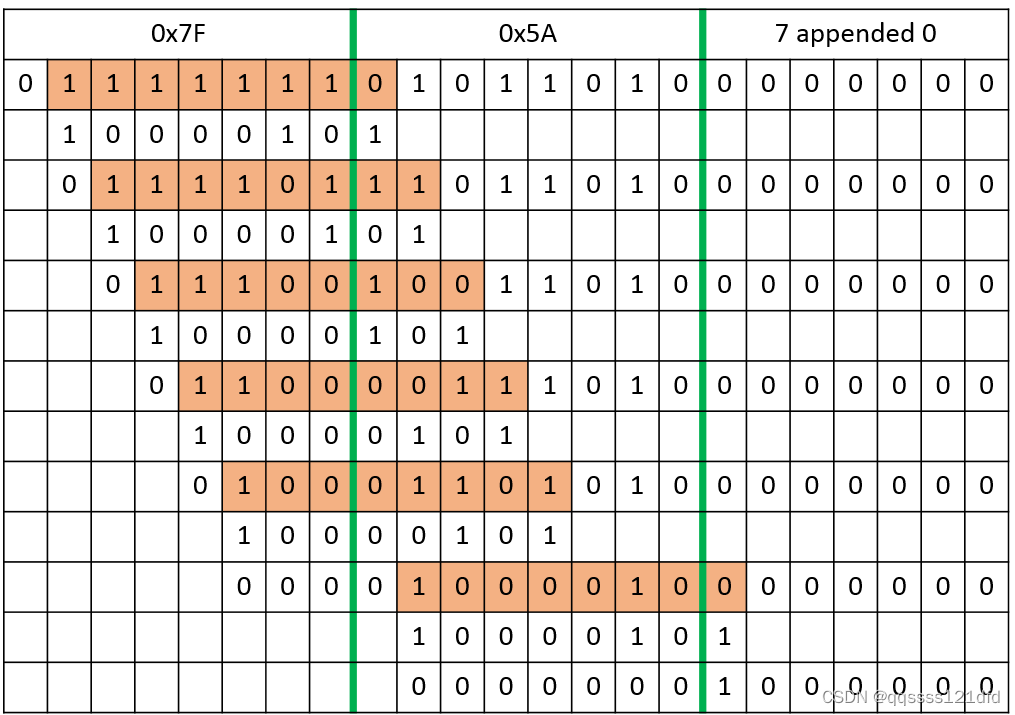
CRC7计算的软件实现上花费了不少时间,因此这里记录一下。图15是数据流
0
x
7
F
,
0
x
5
A
{0x7F,0x5A}
0x7F,0x5A在发生器多项式
x
7
+
x
2
+
1
,
(
0
x
85
)
x^7+x^2+1,(0x85)
x7+x2+1,(0x85)的基础上计算
C
R
C
7
CRC7
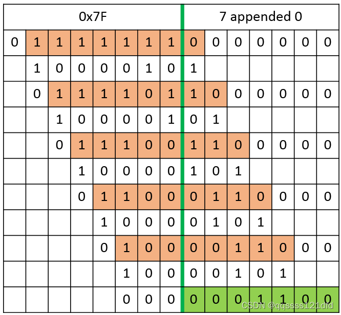
CRC7的流程,图16是数据流
0
x
7
F
{0x7F}
0x7F在发生器多项式
x
7
+
x
2
+
1
,
(
0
x
85
)
x^7+x^2+1,(0x85)
x7+x2+1,(0x85)的基础上计算
C
R
C
7
CRC7
CRC7的流程。
从图15中可以看出数据流经过8次左移之后
c
r
c
_
R
e
m
a
i
n
d
e
r
crc\_Remainder
crc_Remainder的值为
0
x
42
0x42
0x42。图16的计算流程其实可以看做是数据流
0
x
7
F
,
0
x
5
A
{0x7F,0x5A}
0x7F,0x5A在发生器多项式
x
7
+
x
2
+
1
,
(
0
x
85
)
x^7+x^2+1,(0x85)
x7+x2+1,(0x85)的基础上计
C
R
C
7
CRC7
CRC7的过程中处理第一个字节数据
0
x
7
F
0x7F
0x7F的过程且没有代入第二个字节数据
0
x
5
A
0x5A
0x5A里面的比特位。我们从图16可以看出计算完之后的
C
R
C
7
CRC7
CRC7的值为
0
x
18
0x18
0x18(
C
R
C
7
CRC7
CRC7的值放到一个字节数据的高7位,因为在程序中
c
r
c
_
R
e
m
a
i
n
d
e
r
crc\_Remainder
crc_Remainder是一个8比特的字节数据),如果将计算得到的
C
R
C
7
CRC7
CRC7的值放到一个字节数据的低7位的话,也就是将
c
r
c
_
R
e
m
a
i
n
d
e
r
crc\_Remainder
crc_Remainder右移一位, 那么就是
0
x
0
C
0x0C
0x0C。这里
0
x
18
0x18
0x18和
0
x
5
A
0x5A
0x5A的异或操作的结果是
0
x
42
0x42
0x42。
下面我直接贴出了 C R C 7 CRC7 CRC7的软件实现代码,这里参数 c r c R e m a i n d e r S t a r t V a l u e crcRemainderStartValue crcRemainderStartValue代表上一次计算结束的时候的 C R C 7 CRC7 CRC7的结果,且放在8bit字节的低7位(因此代码的最开始有一个左移一位的操作)。参数 P o l y n o m i a l Polynomial Polynomial代表 C R C 7 CRC7 CRC7的发生器多项式对应的字节数据,例如发生器多项式 x 7 + x 2 + 1 x^7+x^2+1 x7+x2+1对应的字节数据为 0 x 85 0x85 0x85。对于 C R C 32 CRC32 CRC32, C R C 16 CRC16 CRC16和 C R C 8 CRC8 CRC8,其对应的发生器多项式分别对应33,17和9个比特数据,但是在软件实现的时候,对应的参数 P o l y n o m i a l Polynomial Polynomial却只用到了其对应的低32,低16和低8位。这里因为 C R C 7 CRC7 CRC7比较特殊,为了软件实现的便利,这里使用了发生器多项式对应的所有8比特数据,而不是低7比特数据。且这里计算完成之后,最后的 C R C 7 CRC7 CRC7的值位于 c r c _ R e m a i n d e r crc\_Remainder crc_Remainder的高7位,因此最后需要有一个右移一位的处理。
uint8_t Compute_Multi_Byte_Data_crc7(uint8_t* byteArray,uint32_t byteArrayLength,uint8_t crcRemainderStartValue,uint8_t Polynomial)
{
    int     bit_index=0;
    uint32_t byte_index=0;
    uint8_t generator_Polynomial = Polynomial;
    uint8_t crc_Remainder = crcRemainderStartValue<<1; /* Initialize crc remainder with zero byte. */
    /* Handle each byte of input stream*/
    for (byte_index=0; byte_index <(byteArrayLength); byte_index++)
    {
        crc_Remainder=crc_Remainder ^ byteArray[byte_index];
        for (bit_index = 0; bit_index <8; bit_index++)
        {
            /* check if MSB is set */
            if ((crc_Remainder & 0x80) != 0)
            {
                /* Perform the 'division' by XORing the crc_Remainder with the generator polynomial */
                crc_Remainder = (uint8_t)(crc_Remainder ^ generator_Polynomial);
                /* MSB set, shift it out of the crc_Remainder and shift in next bit of zero bit.*/
                crc_Remainder = (uint8_t)(crc_Remainder << 1);

            }
            else
            {
                /* MSB not set, shift it out and shift in next bit of zero bit. Same as above, just no division */
                crc_Remainder = (uint8_t)(crc_Remainder << 1);
            }
        }
    }
	crc_Remainder=crc_Remainder>>1;
    return crc_Remainder;
}


 963
963


 被折叠的 条评论
为什么被折叠?
被折叠的 条评论
为什么被折叠?
 到【灌水乐园】发言


