


一、平台总线设备驱动模型
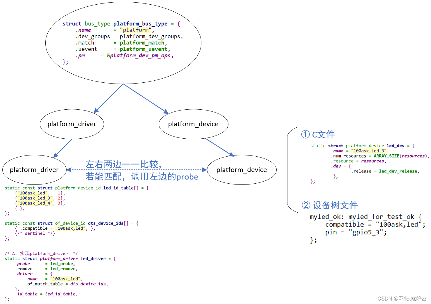
Linux驱动程序开始基于“平台总线设备驱动”模型,把驱动程序分为2边:
- 左边注册一个platform_driver结构体,里面是比较固定、通用的代码
- 右边注册一个platform_device结构体,里面是硬件资源
- 可以通过c文件注册platform_device
- 也可以通过设备树创建节点,内核解析设备树时注册platform_device
二、数据结构
SPI子系统设计2类硬件:SPI控制器、SPI设备
SPI控制器有驱动程序,提供SPI的传输能力
SPI设备也有自己的驱动程序,提供SPI设备的访问能力:
- 知道怎么访问这个设备,知道这个设备的数据什么含义
- 调用SPI控制器的函数来收发数据
2.1 SPI控制器数据结构
相关的源码include\linux\spi\spi.h
struct spi_controller {
    struct device   dev;

    struct list_head list;

    /* other than negative (== assign one dynamically), bus_num is fully
     * board-specific.  usually that simplifies to being SOC-specific.
     * example:  one SOC has three SPI controllers, numbered 0..2,
     * and one board's schematics might show it using SPI-2.  software
     * would normally use bus_num=2 for that controller.
     */
    s16         bus_num;			//如果是负数,则是动态分配,整数指定用哪个spi控制器/驱动(从0开始)

    /* chipselects will be integral to many controllers; some others
     * might use board-specific GPIOs.
     */
    u16         num_chipselect;		//片选信号的个数,也就是从设备的数量,从设备个数0~num_chipselect,可以有没有连接的从设备

    /* some SPI controllers pose alignment requirements on DMAable
     * buffers; let protocol drivers know about these requirements.
     */
    u16         dma_alignment;

    /* spi_device.mode flags understood by this controller driver */
    u16         mode_bits;		//控制器启动的模式位,被控制器驱动解析

    /* bitmask of supported bits_per_word for transfers */
    u32         bits_per_word_mask;
#define SPI_BPW_MASK(bits) BIT((bits) - 1)
#define SPI_BIT_MASK(bits) (((bits) == 32) ? ~0U : (BIT(bits) - 1))
#define SPI_BPW_RANGE_MASK(min, max) (SPI_BIT_MASK(max) - SPI_BIT_MASK(min - 1))

    /* limits on transfer speed */
    u32         min_speed_hz;
    u32         max_speed_hz;

    /* other constraints relevant to this driver */
    u16         flags;			//全双工、半双工等
#define SPI_CONTROLLER_HALF_DUPLEX  BIT(0)  /* can't do full duplex */
#define SPI_CONTROLLER_NO_RX        BIT(1)  /* can't do buffer read */
#define SPI_CONTROLLER_NO_TX        BIT(2)  /* can't do buffer write */
#define SPI_CONTROLLER_MUST_RX      BIT(3)  /* requires rx */
#define SPI_CONTROLLER_MUST_TX      BIT(4)  /* requires tx */

#define SPI_MASTER_GPIO_SS      BIT(5)  /* GPIO CS must select slave */

    /* flag indicating this is an SPI slave controller */
    bool            slave;

    /*
     * on some hardware transfer / message size may be constrained
     * the limit may depend on device transfer settings
     */
    size_t (*max_transfer_size)(struct spi_device *spi);
    size_t (*max_message_size)(struct spi_device *spi);

    /* I/O mutex */
    struct mutex        io_mutex;

    /* lock and mutex for SPI bus locking */
    spinlock_t      bus_lock_spinlock;
    struct mutex        bus_lock_mutex;

    /* flag indicating that the SPI bus is locked for exclusive use */
    bool            bus_lock_flag;

    /* Setup mode and clock, etc (spi driver may call many times).
     *
     * IMPORTANT:  this may be called when transfers to another
     * device are active.  DO NOT UPDATE SHARED REGISTERS in ways
     * which could break those transfers.
     */
    int         (*setup)(struct spi_device *spi);		//时钟和spi模式的设置函数

    /* bidirectional bulk transfers
     *
     * + The transfer() method may not sleep; its main role is
     *   just to add the message to the queue.
     * + For now there's no remove-from-queue operation, or
     *   any other request management
     * + To a given spi_device, message queueing is pure fifo
     *
     * + The controller's main job is to process its message queue,
     *   selecting a chip (for masters), then transferring data
     * + If there are multiple spi_device children, the i/o queue
     *   arbitration algorithm is unspecified (round robin, fifo,
     *   priority, reservations, preemption, etc)
     *
     * + Chipselect stays active during the entire message
     *   (unless modified by spi_transfer.cs_change != 0).
     * + The message transfers use clock and SPI mode parameters
     *   previously established by setup() for this device
     */
    int         (*transfer)(struct spi_device *spi,
                        struct spi_message *mesg);

    /* called on release() to free memory provided by spi_controller */
    void            (*cleanup)(struct spi_device *spi);

    /*
     * Used to enable core support for DMA handling, if can_dma()
     * exists and returns true then the transfer will be mapped
     * prior to transfer_one() being called.  The driver should
     * not modify or store xfer and dma_tx and dma_rx must be set
     * while the device is prepared.
     */
    bool            (*can_dma)(struct spi_controller *ctlr,
                       struct spi_device *spi,
                       struct spi_transfer *xfer);

    /*
     * These hooks are for drivers that want to use the generic
     * controller transfer queueing mechanism. If these are used, the
     * transfer() function above must NOT be specified by the driver.
     * Over time we expect SPI drivers to be phased over to this API.
     */
    bool                queued;
    struct kthread_worker       kworker;
    struct task_struct      *kworker_task;
    struct kthread_work     pump_messages;
    spinlock_t          queue_lock;
    struct list_head        queue;
    struct spi_message      *cur_msg;		//正在处理的spi_message
    bool                idling;
    bool                busy;
    bool                running;
    bool                rt;
    bool                auto_runtime_pm;
    bool                            cur_msg_prepared;
    bool                cur_msg_mapped;
    struct completion               xfer_completion;
    size_t              max_dma_len;

    int (*prepare_transfer_hardware)(struct spi_controller *ctlr);
    int (*transfer_one_message)(struct spi_controller *ctlr,
                    struct spi_message *mesg);
    int (*slave_abort)(struct spi_controller *ctlr);

    /*
     * These hooks are for drivers that use a generic implementation
     * of transfer_one_message() provied by the core.
     */
    void (*set_cs)(struct spi_device *spi, bool enable);
    int (*transfer_one)(struct spi_controller *ctlr, struct spi_device *spi,
                struct spi_transfer *transfer);		//传输的硬件层的实现
    void (*handle_err)(struct spi_controller *ctlr,
               struct spi_message *message);

    /* Optimized handlers for SPI memory-like operations. */
    const struct spi_controller_mem_ops *mem_ops;

    /* gpio chip select */
    int         *cs_gpios;

    /* statistics */
    struct spi_statistics   statistics;

    /* DMA channels for use with core dmaengine helpers */
    struct dma_chan     *dma_tx;
    struct dma_chan     *dma_rx;

    /* dummy data for full duplex devices */
    void            *dummy_rx;
    void            *dummy_tx;

    int (*fw_translate_cs)(struct spi_controller *ctlr, unsigned cs);
};
Linux中使用结构体描述SPI控制器,其中最重要的是transfer函数,它用来手法数据的函数。
2.2 SPI设备的数据结构
相关的源码include\linux\spi\spi.h
struct spi_device {
	struct device		dev;
	struct spi_controller	*controller;
	struct spi_controller	*master;	/* compatibility layer */
	u32			max_speed_hz;
	u8			chip_select;
	u8			bits_per_word;
	u16			mode;
#define	SPI_CPHA	0x01			/* clock phase */
#define	SPI_CPOL	0x02			/* clock polarity */
#define	SPI_MODE_0	(0|0)			/* (original MicroWire) */
#define	SPI_MODE_1	(0|SPI_CPHA)
#define	SPI_MODE_2	(SPI_CPOL|0)
#define	SPI_MODE_3	(SPI_CPOL|SPI_CPHA)
#define	SPI_CS_HIGH	0x04			/* chipselect active high? */
#define	SPI_LSB_FIRST	0x08			/* per-word bits-on-wire */
#define	SPI_3WIRE	0x10			/* SI/SO signals shared */
#define	SPI_LOOP	0x20			/* loopback mode */
#define	SPI_NO_CS	0x40			/* 1 dev/bus, no chipselect */
#define	SPI_READY	0x80			/* slave pulls low to pause */
#define	SPI_TX_DUAL	0x100			/* transmit with 2 wires */
#define	SPI_TX_QUAD	0x200			/* transmit with 4 wires */
#define	SPI_RX_DUAL	0x400			/* receive with 2 wires */
#define	SPI_RX_QUAD	0x800			/* receive with 4 wires */
	int			irq;
	void			*controller_state;
	void			*controller_data;
	char			modalias[SPI_NAME_SIZE];
	int			cs_gpio;	/* chip select gpio */

	/* the statistics */
	struct spi_statistics	statistics;

	/*
	 * likely need more hooks for more protocol options affecting how
	 * the controller talks to each chip, like:
	 *  - memory packing (12 bit samples into low bits, others zeroed)
	 *  - priority
	 *  - drop chipselect after each word
	 *  - chipselect delays
	 *  - ...
	 */
};
三、SPI框架
 SPI控制器是platform框架下的,通过对比"spi-gpio"关键字,匹配到spi_master设备。
然后在probe函数中,解析设备树的子节点。生成spi_device
3.1 SPI控制器驱动程序
SPI控制器可以基于平台总线设备驱动模型来实现:
- 在设备树里描述SPI控制器的硬件信息,在设备树子节点里描述挂在下面的SPI设备信息
- 在platform_dirver中提供一个probe函数
- 它会注册一个spi_master
- 解析设备树子节点,创建spi_device结构体
3.2 SPI设备驱动程序
类似于平台总线驱动模型,Linux有一个SPI总线设备驱动模型
- 左边是spi_driver,使用C文件实现,里面有id_table表示能支持哪些SPI设备,有probe函数
- 右边是spi_device,用来描述SPI设备,比如它的片选引脚、频率
- 可以来自设备树:比如由SPI控制器驱动程序解析设备树后创建、注册spi_device
- 可以来自C文件:比如使用spi_register_board_info创建、注册spi_device


 1745
1745


 被折叠的 条评论
为什么被折叠?
被折叠的 条评论
为什么被折叠?
 到【灌水乐园】发言


