


Itead Studio Sonoff SC Revisited
A few months ago I wrote about the Sonoff SC sensor hub by Itead Studio. It’s a device with a Sharp GP2Y1010AU0F [Aliexpress] dust sensor, a DHT11 humidity and temperature sensor, an LDR as light sensor and a mic. The sensors are driven by an ATMega328P microcontroller but there is also an ESP8266 on board for WiFi communication, a pretty standard set up when you have several sensors and the ESP8266 GPIOs are just not enough.
几个月前,我写了一篇关于Itead Studio的Sonoff SC sensor hub的文章。 该设备具有Sharp GP2Y1010AU0F [Aliexpress]灰尘传感器,DHT11湿度和温度传感器,LDR光传感器和麦克风。 传感器由ATMega328P微控制器驱动,但还有一个用于WiFi通信的ESP8266,当您有几个传感器并且ESP8266 GPIO仅仅是不够的时候,这是一个非常标准的设置。
On the first post I already did a small mod to replace the DHT11 humidity and temperature sensor with a more accurate and pin compatible DHT22. Since then, several readers have contributed with code and ideas. My progress implementing and testing them is slow, so I though about writing a first post about some modifications I (and others) have done to the device.
So this is a work in progress post. At the moment, all the code for these modifications is in the dev branch of the repository.
This custom Sonoff SC firmware is released as free open software and can be checked out at my SonoffSC repository on Github.
在上一篇文章中,我已经做了一个小型模块:具有更精确的、引脚兼容的DHT22来更换DHT11湿度和温度传感器。 从那时起,几位读者对代码和想法做出了贡献。 我实施和测试的进度是缓慢的,所以我写了关于我(和其他人)对设备所做的一些修改的一篇文章。
所以这是一个正在进行的博文。 目前,这些修改的所有代码都在存储库的开发分支中。
该自定义Sonoff SC固件作为免费开放软件发布,可以在我的SonoffSC存储库Github上检出。
Flashing the ATMega328p via bootloader
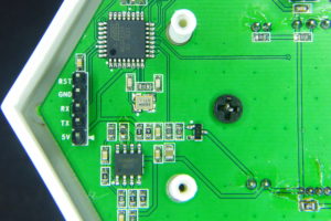
First I’d like to say is that, although I used a AVR programmer for the ATMega328 in my last post this is not required. You can use an FTDI USB to TTL [Ebay, also Aliexpress] board to flash the AVR too since it comes with the Arduino bootloader.
Just remember to connect TX to TX and RX to RX since the pins in the board are labeled from the programmer point of view. Connect RST to the DTR line and the power lines and you are good to go.
通过BootLoader更新ATMega328p
首先我想说的是,尽管我在最后一篇文章中使用了一个AVR编程器,但这不是必需的。 您也可以使用FTDI USB to TTL板来刷AVR,因为它自带Arduino BootLoader。
只需记住将TX连接到TX和RX到RX,因为板上的引脚标记是以编程器的角度标记的。 将RST连接到DTR线和电源线,刷机将会很顺利。
Adding a microwave radar as presence sensor
Now, this is a suggestion in the issues section of the repository. Since the usual PIR sensors are quite bulky my first idea was to use one of those nice Panasonic EKMB PIR [Ebay]. They are small, very sensitive (with versions with up to 12m detection) and really expensive. They are ultra low power devices meant for low power sensors, but that’s not the case here.
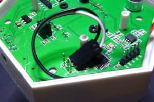
So I moved to a microwave sensor I first spotted at Scargill tech blog. This is a 5.8GHz microwave sensor [Ebay, also on Aliexpress] that costs around 1.5 USD, has a configurable range of up to 8 meters and a detection pulse that’s 30s by default. The device can “sense” movement even through a thin wall so the SonoffSC enclosure is no big deal. But after a few tests I realized it was capturing people on the street outside my house so I decided to replace the resistor in R9_1 with a 100k one. Now the range is about 3-4 meters, safely covering the main walking paths in my livingroom. I also added a noise filter in the power line using a capacitor and a resistor as per Pete’s advice.
添加微波雷达作为存在传感器
现在,这是存储库的问题部分的一个建议。由于通常的PIR传感器非常庞大,我的第一个想法是使用一个漂亮的松下EKMB PIR。它们很小,非常敏感(具有高达12m检测的版本),并且真的很贵。它们设计用于低功率传感器器件,但情况并非如此。
所以我开始关注微波传感器,第一次发现在Scargill科技博客。这是一个5.8GHz的微波传感器,成本约为1.5美元,可配置范围高达8米,默认情况下为30秒的检测脉冲。该设备可以“感觉”运动,即使通过一个薄壁,所以SonoffSC外壳是没有什么大不了的。但经过几次测试,我意识到它正在我家外面的街道上捕获人,所以我决定用R9K替换一个100k的电阻。现在的距离约3-4米,安全地覆盖了我的客厅里的主要步行路线。根据彼得的建议,我还使用电容器和电阻器在电源线中添加了一个噪声滤波器。
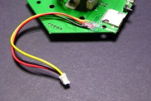
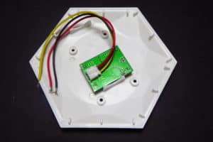
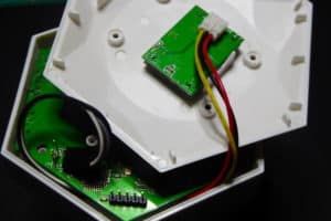
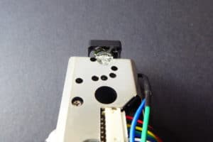
The placement of the sensor is still under testing. Right now I have it on the base of the SonoffSC, hot glued to it with the cables running to the oposite side of the board. Even thou the placement is neat, I have found that sometimes it misses a moving target, still testing if it’s due to the microwave beam or the code.
传感器的放置仍在测试之中。 现在我把它放到在SonoffSC的基板上,用电缆连接到电路板的对面。 即使你的位置是整齐的,我发现有时它错过了一个移动的目标,仍然测试是微波束或代码的原因。
Since GPIO13 has no interrupts on the ATMega328P the code checks in the main loop for the pin state. If it changes it immediately reports the change to the ESP8266 via serial.
由于GPIO13在ATMega328P上没有中断,所以代码在Loop中检查引脚状态。 如果状态更改,它会立即通过串口向ESP8266报告变化。
Adding an RGB LED ring – again
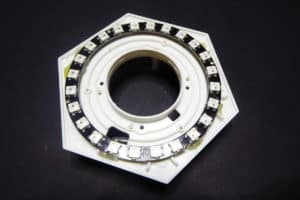
Actually this one was already done thanks to the contributions by Blair Thompson (check his video here). But I decided to go for a slighly different path. The ring is a 24 WS2812 LED ring [Ebay, also on Aliexpress] placed in the middle compartment of the enclosure. The VCC, GND and DI lines are brought out and connected to the ISP header like with the microwave sensor using GPIO 12 (MISO) now. Just like Blair’s approach.
实际上,由于布莱尔·汤普森(Blair Thompson)的贡献(在这里查看他的视频),这一切已经完成了。 但我决定走一条不同寻常的道路。 灯环是一个24 WS2812 LED ring放置在外壳的中间隔间。 将VCC,GND和DI线引出并连接到ISP接头,就像使用GPIO 12(MISO)的微波传感器一样。 这跟布莱尔的做法一样。
WS2812FX
The difference with Blair’s code is in the library I’m using. On top of the Adafruit NeoPixel library I’m using the WS2812FX library by Harm Aldick (kitesurfer1404). The library defines an indexed list of effects for LED stripes and so. Very convenient to be called from a remote MQTT based RPC.
Another incompatible change is that by default (although this might change in the final version) it performs a blue fade in when movement is detected and fades out when no movement. This behaviour is hardcoded in the current dev branch but I might:
- Allow the user to configure the behaviour via the web interface
- Use an external service (Node-RED) to write the business inteligence and just send data and receive instructions via MQTT
I like the second option better, moving the intelligence outside the device looks reasonable and more flexible. But I’m aware most users might want to have the behaviour embedded…
Blair’s code is still in the master branch, version 0.3.0. Once the current dev branch is merged to master it will be tagged as version 1.0.0.
与Blair的代码不同之处在于我正在使用的库。在Adafruit NeoPixel库中,我使用的是Harm Aldick(kitesurfer1404)的WS2812FX库。这个库定义了LED 灯带的索引列表。使用基于RPC的MQTT,从远程调用非常方便。
另一个不相容的变化是,默认情况下(尽管这可能会在最终版本中发生变化),当移动被检测到时,它会执行蓝色淡入,而没有移动时蓝色淡出。这个行为是硬编码在当前的开发分支,但我可能:
- 允许用户通过Web界面配置行为
- 使用外部服务(Node-RED)来编写业务智能,只需通过MQTT发送数据和接收指令
我更喜欢第二选择,设备外的智能看起来合理,更灵活。但我知道大多数用户可能想要嵌入行为。
Blair的代码仍然在主分支,版本0.3.0。一旦当前的dev分支合并成master,它将被标记为1.0.0版本。
Adding a mini-fan to improve dust sensor readings
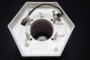
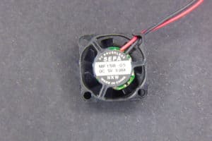
One of the issues several people have detected is that the dust sensor has very little range. This is probably due to it being inside an enclosure with little air vent. There was a little debate about it in the repo and I decided to try a small SEPA MF15B-05 5V fan I found on Aliexpress. It’s a 15x15mm 0.06A fan.
几个人遇到到的问题之一是灰尘传感器的范围很小。 这可能是因为它在一个没有排气口的外壳内。 在repo中有一些争议:我决定尝试在Aliexpress上发现的一款小型SEPA MF15B-05 5V风扇。 这是一个15x15mm的0.06A风扇。
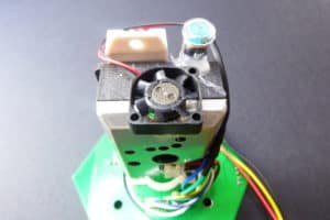
The fan is driven by the LED signal in the board (GPIO7). I decided to hot glue it on top of the dust sensor so it forces the air to flow from the outside of the enclosure down. Whenever a new dust reading is scheduled or requested, the fan starts up for 5 seconds before the reading is actually performed. I have also changed the code to use ug/m3 instead of mg/m3.
风扇由板上的LED信号驱动(GPIO7)。 我决定用胶粘到灰尘传感器的顶部,这样它迫使空气从外壳的外部流出。 每当安排或要求新的尘埃读数时,风扇在实际执行读数之前启动5秒钟。 我也将代码改为使用ug / m3而不是mg / m3。
I have been testing it for the last 2 days. Still not enough data but it looks like the daily average value is twice the value it used to be and the standard deviation is also greater. I still have to test with the fan running for a longer time (or even all the time) before reading the sensor data. The good thing is that the fan is noise-less (as far as I can hear).
我已经测试了近2天。 仍然没有足够的数据,但它看起来像日平均值是它曾经的两倍,标准偏差也更大。 在读取传感器数据之前,我仍然需要测试较长的风扇运行时间(甚至是一直运行)。 好的是,风扇是静音的(据我所知)。
Changes in the code
The code has also gone through a major review. Basically importing features from the ESPurna project. Aside from the changes to support the new functionalities in this post, other main changes include:
- Improvements in the SerialLink library (now it allows long integers as argument, good for RGB values)
- Debug via UDP (using Serial is not possible since it’s the communication channel between both microcontrollers)
- Moved debug strings to program memory
- Embed the webserver pages and resources into the firmware (faster, more free room for code): will write about it soon
There are already some other minor changes, improvements, bug fixes. I want to include more issues from the repo before merging this to master. Some of these improvements include new sensors. At some point you will have to choose from the different options since there are just so many GPIOs.
该代码也经过重大审查。 基本上从ESPurna项目导入功能。 除了支持文中的新功能的变化外,其他主要变化包括:
- SerialLink库的改进(现在它允许长整数作为参数,对RGB值有好处)
- 通过UDP调试(使用串口是不可能的,因为它用于两个微控制器之间的通信)
- 将调试字符串移动到程序存储器
- 将网页服务器页面和资源嵌入固件(更快,更少的空间占用):将很快写出
也有一些其他微小的变化,改进,bug修复。 我想在归并到主线之前从repo中合并更多的问题。 其中一些改进包括新的传感器。 在某些时候,您将不得不选择不同的选项,因为有这么多的GPIO。
Flashing
Remember you will have to flash both microcontrollers again. But this time it won’t be necessary to flash the SPIFFS partition on the ESP8266. You can flash both using an FTDI USB to TTL programmer like the one I linked before. While flashing remove the communication jumpers. Also remember that the pins are labeled from the programmer point of view.
Since there are changes in the memory layout, erase the ESP8266 flash memory prior to upload the new code. The new layout is the 1m64 (1 Mbyte with 64Kbytes for SPIFFS). If you are using PlatformIO these settings are defined in the project file. Otherwise you will have to select the right option from the Arduino menu if you want OTA to work.
That’s it. As I have already said this is a work in progress so there might be changes and new additions to the project. Check the repo from time to time. I’m aware there are missing details here and there so don’t hesitate in asking. And thanks for reading me
记住,您将不得不再次烧录两个微控制器。 但是这次不需要在ESP8266上刷新SPIFFS分区。 您可以使用之前FTDI USB to TTL编程器。 烧录时时清除通讯跳线。 还要记住,引脚是从编程器的角度来标记的。
由于存储器布局有变化,因此在上传新代码之前,请先擦除ESP8266闪存。 新的布局是1m64(1MB,64KB的SPIFFS)。 如果您正在使用PlatformIO,这些设置将在项目文件中定义。 如果要使OTA工作,您将不得不从Arduino菜单中选择正确的选项。
正如我已经说过的,这是一项正在进行的工作,所以可能会有改变和新增的项目。 请及时检查repo。 我知道这里有丢失的细节,所以请不要犹豫。 谢谢你阅读?


 3639
3639

 被折叠的 条评论
为什么被折叠?
被折叠的 条评论
为什么被折叠?
 到【灌水乐园】发言


