


Path类继承自Shape,可以绘制很多简单的,复合的图形。Path类通过提供的Data属性,Data属性接受一个Geometry对象(我的理解就是Data要装什么集合图形呀),Geometry一共有7个派生类,说明如下:
| 名称 | 说明 |
| LineGeometry | 绘制直线 |
| RectangleGeometry | 绘制矩形(包括原型拐角的举行) |
| EllipseGeometry | 绘制椭圆 |
| GeometryGroup | 通过组合的形式添加多个Geometry对象,使用EvenOdd(具有穿透效果)或NonZero填充规则确定填充区域;
|
| CombinedGeomotry | 合并两个几何图形,通过CombineMode属性控制合并方式。 |
| PathGeometry | 制作复杂的几何图形,弧线,曲线等。 |
| StreamGeometry | 不太常用,不介绍啦 |
下面 通过图例的方式一次介绍这些Geometry。
1.LineGeometry。通过StartPoint,EndPoint两个点确定一条直线。
2.RectangleGeometry。通过Rect属性确定左上角,右下角两个点位置画出矩形。
3.EllipseGeometry。RadiousX确定横向半径,RadiousY确定纵向半径,Center确定椭圆的圆心位置。以下为示例:
<Grid>
        <Grid.RowDefinitions>
            <RowDefinition ></RowDefinition>
            <RowDefinition></RowDefinition>
            <RowDefinition></RowDefinition>
        </Grid.RowDefinitions>
        <Grid.ColumnDefinitions>
            <ColumnDefinition Width="Auto"></ColumnDefinition>
            <ColumnDefinition Width="Auto"></ColumnDefinition>
        </Grid.ColumnDefinitions>
        <Label Grid.Row="0" Grid.Column="0" Content="LineGeometry:" VerticalAlignment="Center"></Label>
        <Canvas Grid.Row="0" Grid.Column="1">
            <Path Fill="Yellow" Stroke="Blue" StrokeThickness="5">
                <Path.Data>
                    <LineGeometry StartPoint="10,50" EndPoint="200,50"></LineGeometry>
                </Path.Data>
            </Path>
        </Canvas>
        <Label Grid.Row="1" Grid.Column="0" Content="RectangleGeometry:" VerticalAlignment="Center"></Label>
        <Canvas Grid.Row="1" Grid.Column="1">
            <Path Fill="Yellow" Stroke="Blue" StrokeThickness="5">
                <Path.Data>
                    <RectangleGeometry Rect="40,10 100,70"></RectangleGeometry>
                </Path.Data>
            </Path>
        </Canvas>
        <Label Grid.Row="2" Grid.Column="0" Content="EllipseGeometry:" VerticalAlignment="Center"></Label>
        <Canvas Grid.Row="2" Grid.Column="2">
            <Path Fill="Yellow" Stroke="Blue" StrokeThickness="5">
                <Path.Data>
                    <EllipseGeometry RadiusX="35" RadiusY="35" Center="90,45"></EllipseGeometry>
                </Path.Data>
            </Path>
        </Canvas>
    </Grid>
运行效果:

4.GeometryGroup。在Group中添加多个图形,这样的好处是降低开销。这个示例在我的上一篇有介绍,这里就不在重复说明了,链接如下:https://blog.csdn.net/chulijun3107/article/details/105351693
5.CombinedGeomotry。Combined的字面意思是联合,那这个就是要取两个图形联合的情况了,那究竟是取相交部分?联合部分?还是其他呢?GeometryCombineMode属性来体现,枚举值如下:
| 枚举值 | 说明 |
| Union | 两个图形所有部分 |
| Intersect | 两个图形相交部分 |
| Xor | 两个图形的非公有部分 |
| Exclude | 第一个图形的所有部分,不包含第二个图形的分部 |
下边看一个例子来说明这几个枚举值的作用:
  <Window.Resources>
        <RectangleGeometry x:Key="rect" Rect="0 0 100 100"></RectangleGeometry>
        <EllipseGeometry x:Key="ellipse" Center="85 50" RadiusX="65" RadiusY="35"></EllipseGeometry>
    </Window.Resources>
    <Grid Margin="5" TextBlock.FontSize="16">
        <Grid.RowDefinitions>
            <RowDefinition Height="Auto"></RowDefinition>
            <RowDefinition Height="Auto"></RowDefinition>
            <RowDefinition Height="Auto"></RowDefinition>
            <RowDefinition Height="Auto"></RowDefinition>
        </Grid.RowDefinitions>
        <Grid.ColumnDefinitions>
            <ColumnDefinition Width="Auto"></ColumnDefinition>
            <ColumnDefinition Width="Auto"></ColumnDefinition>
        </Grid.ColumnDefinitions>
        <TextBlock Grid.Column="0" Margin="10" VerticalAlignment="Center">Union</TextBlock>
        <Path Grid.Column="1" Fill="Yellow" Stroke="Blue" Margin="5">
            <Path.Data>
                <CombinedGeometry GeometryCombineMode="Union" CombinedGeometry.Geometry1="{StaticResource rect}" CombinedGeometry.Geometry2="{StaticResource ellipse}"></CombinedGeometry>
            </Path.Data>
        </Path>
        <TextBlock Grid.Row="1" Grid.Column="0" Margin="10" VerticalAlignment="Center">Intersect</TextBlock>
        <Path Grid.Row="1" Grid.Column="1" Fill="Yellow" Stroke="Blue" Margin="5">
            <Path.Data>
                <CombinedGeometry GeometryCombineMode="Intersect"  CombinedGeometry.Geometry1="{StaticResource rect}" CombinedGeometry.Geometry2="{StaticResource ellipse}"></CombinedGeometry>
            </Path.Data>
        </Path>
        <TextBlock Grid.Row="2" Grid.Column="0" Margin="10" VerticalAlignment="Center">Xor</TextBlock>
        <Path Grid.Row="2" Grid.Column="2" Fill="Yellow" Stroke="Blue" Margin="5">
            <Path.Data>
                <CombinedGeometry GeometryCombineMode="Xor"  CombinedGeometry.Geometry1="{StaticResource rect}" CombinedGeometry.Geometry2="{StaticResource ellipse}"></CombinedGeometry>
            </Path.Data>
        </Path>
        <TextBlock Grid.Row="3" Grid.Column="0" Margin="10" VerticalAlignment="Center">Exclude</TextBlock>
        <Path Grid.Row="3" Grid.Column="1" Fill="Yellow" Stroke="Blue" Margin="5">
            <Path.Data>
                <CombinedGeometry GeometryCombineMode="Exclude"  CombinedGeometry.Geometry1="{StaticResource rect}"  CombinedGeometry.Geometry2="{StaticResource ellipse}"></CombinedGeometry>
            </Path.Data>
        </Path>
    </Grid>
运行效果:

下面我们做一个稍微复杂的图形,禁止停车的图案。原图如下,这个图案的组成是外边一个红色的圆,StrokeThickness值设置大一些,Fill用蓝色,然后两个左右倾斜45°的矩形组成。当然你也可以用两条足够粗的线段。

好的,我们看一下代码如何实现:
先实现红色圆部分和两个旋转的矩形:
<Canvas>
<Path Fill="Red" >
<Path.Data>
<CombinedGeometry GeometryCombineMode="Union">
<CombinedGeometry.Geometry1>
<CombinedGeometry GeometryCombineMode="Exclude">
<CombinedGeometry.Geometry1>
<EllipseGeometry Center="50,50" RadiusX="50" RadiusY="50"></EllipseGeometry>
</CombinedGeometry.Geometry1>
<CombinedGeometry.Geometry2>
<EllipseGeometry Center="50,50" RadiusX="37" RadiusY="37"></EllipseGeometry>
</CombinedGeometry.Geometry2>
</CombinedGeometry>
</CombinedGeometry.Geometry1>
<CombinedGeometry.Geometry2>
<CombinedGeometry GeometryCombineMode="Union">
<CombinedGeometry.Geometry1>
<RectangleGeometry Rect="44,5 10,90">
<RectangleGeometry.Transform>
<RotateTransform Angle="45" CenterX="50" CenterY="50"></RotateTransform>
</RectangleGeometry.Transform>
</RectangleGeometry>
</CombinedGeometry.Geometry1>
<CombinedGeometry.Geometry2>
<RectangleGeometry Rect="44,5 10,90">
<RectangleGeometry.Transform>
<RotateTransform Angle="135" CenterX="50" CenterY="50"></RotateTransform>
</RectangleGeometry.Transform>
</RectangleGeometry>
</CombinedGeometry.Geometry2>
</CombinedGeometry>
</CombinedGeometry.Geometry2>
</CombinedGeometry>
</Path.Data>
</Path>
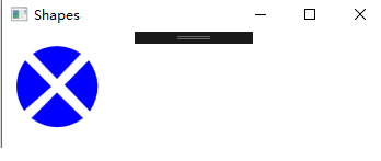
</Canvas>运行效果是这样的,还没有在中间添加蓝色,因为要用到接下来的PathGeometry。

6.PathGeometry。绘图逻辑。PathFigure是几何图形的子部分,它可以包含LineSegment,ArcSegment,以下图为例,StartPoint设置了扇形的起点。然后通过LineSegment绘制一条直线。ArcSegment 的Point属性设置扇形的起点,Size设置扇形的横向,纵向圆的半径。然后绘制4个扇形组成上边的禁止停车标志。
<Path Fill="Blue">
            <Path.Data>
                <PathGeometry>
                    <PathFigure StartPoint="57,48.5">
                        <LineSegment Point="79,26"></LineSegment>
                        <ArcSegment Point="80,72.5" Size="68,50" SweepDirection="Clockwise"></ArcSegment>
                        <LineSegment Point="57,48.5"></LineSegment>
                    </PathFigure>
                </PathGeometry>
            </Path.Data>
        </Path>
看看绘制四个扇形的效果:
好,我们最后把这红色和蓝色的组合在一起:

图标源码地址:
我们再做个联系,通过旋转图形绘制三菱车车标。这是我在网上找到的原图标图案:

做三个菱形,然后旋转-115度,115度。就可以了。
 <Canvas Width="120" Height="120" >
        <Path Stroke="Red" Fill="Red">
            <Path.Data>
                <PathGeometry>
                    <PathFigure IsClosed="True" StartPoint="50,0">
                        <LineSegment Point="75,50"></LineSegment>
                        <LineSegment Point="50,100"></LineSegment>
                        <LineSegment Point="25,50"></LineSegment>
                    </PathFigure>
                </PathGeometry>
            </Path.Data>
        </Path>
        <Path Stroke="Red" Fill="Red">
            <Path.Data>
                <PathGeometry>
                    <PathFigure IsClosed="True" StartPoint="50,0">
                        <LineSegment Point="75,50"></LineSegment>
                        <LineSegment Point="50,100"></LineSegment>
                        <LineSegment Point="25,50"></LineSegment>
                    </PathFigure>
                    <PathGeometry.Transform>
                        <RotateTransform Angle="-115" CenterX="50" CenterY="100"></RotateTransform>
                    </PathGeometry.Transform>
                </PathGeometry>

            </Path.Data>
        </Path>
        <Path Stroke="Red" Fill="Red">
            <Path.Data>
                <PathGeometry>
                    <PathFigure IsClosed="True" StartPoint="50,0">
                        <LineSegment Point="75,50"></LineSegment>
                        <LineSegment Point="50,100"></LineSegment>
                        <LineSegment Point="25,50"></LineSegment>
                    </PathFigure>
                    <PathGeometry.Transform>
                        <RotateTransform Angle="115" CenterX="50" CenterY="100"></RotateTransform>
                    </PathGeometry.Transform>
                </PathGeometry>
            </Path.Data>
        </Path>
    </Canvas>
运行效果如下:


 304
304


 被折叠的 条评论
为什么被折叠?
被折叠的 条评论
为什么被折叠?
 到【灌水乐园】发言


