


使用的是ESP8266 and ESP32 OLED driver for SSD1306 displays
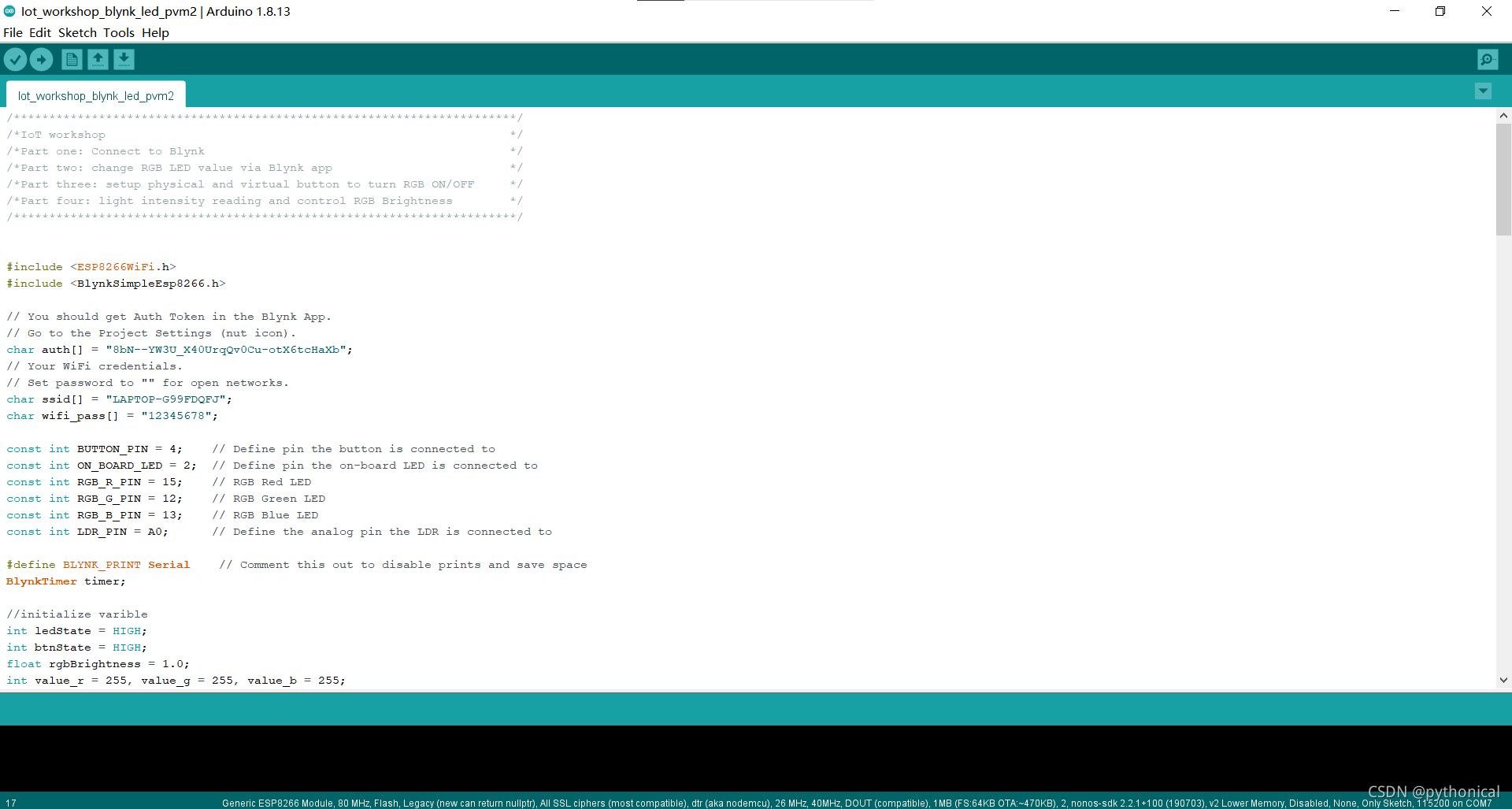
通过Arduino编写和部署代码,安装依赖
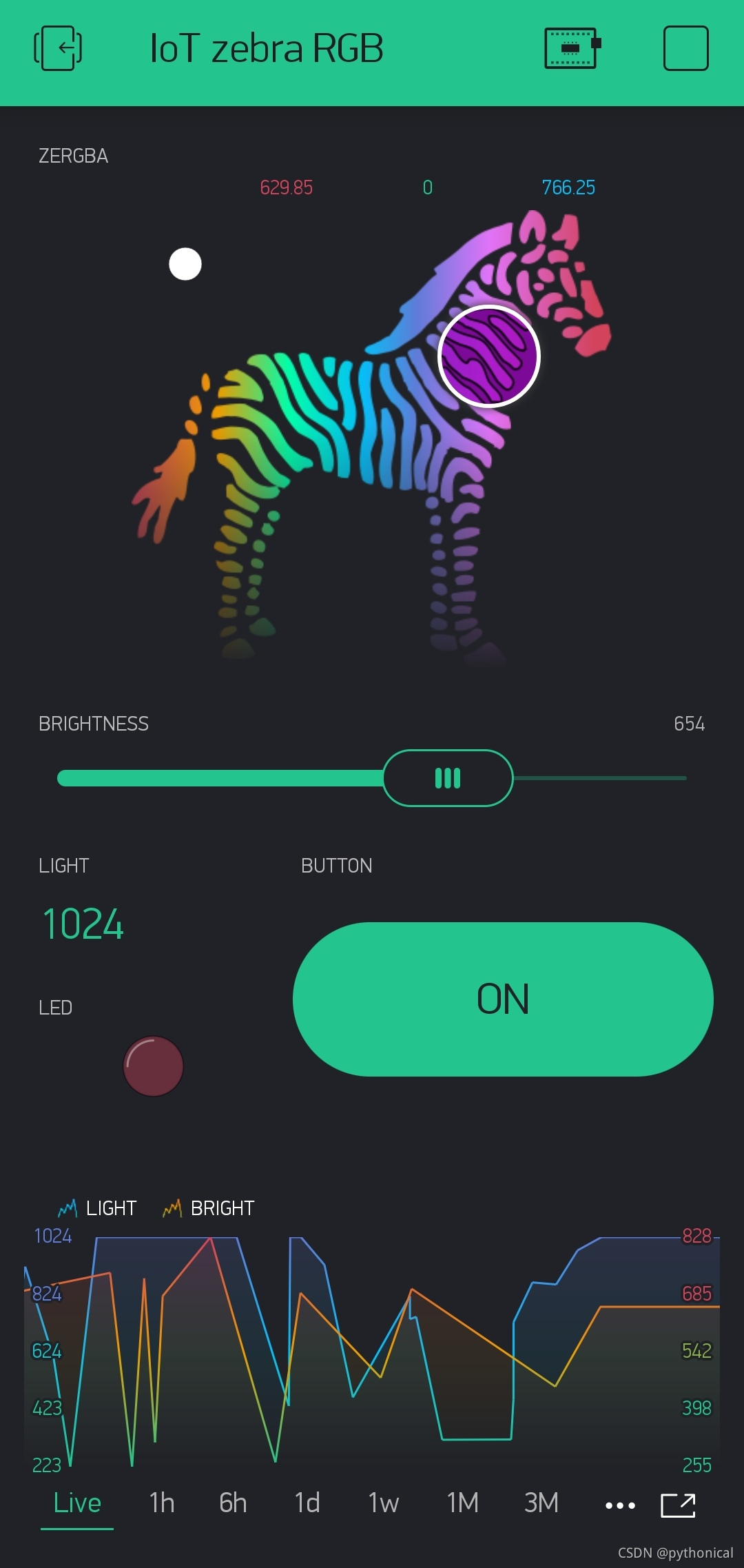
通过Blynk APP控制LED灯的颜色、亮度,以及展示数据
/***********************************************************************/
/*IoT workshop                                                         */
/*Part one: Connect to Blynk                                           */
/*Part two: change RGB LED value via Blynk app                         */
/*Part three: setup physical and virtual button to turn RGB ON/OFF     */
/*Part four: light intensity reading and control RGB Brightness        */
/***********************************************************************/


#include <ESP8266WiFi.h>
#include <BlynkSimpleEsp8266.h>

// You should get Auth Token in the Blynk App.
// Go to the Project Settings (nut icon).
char auth[] = "YOUR-AUTH-CODE";
// Your WiFi credentials.
// Set password to "" for open networks.
char ssid[] = "YOUR-WIFI-SSID";
char wifi_pass[] = "YOUR-WIFI-PASSWORD";

const int BUTTON_PIN = 4;    // Define pin the button is connected to
const int ON_BOARD_LED = 2;  // Define pin the on-board LED is connected to
const int RGB_R_PIN = 15;    // RGB Red LED
const int RGB_G_PIN = 12;    // RGB Green LED
const int RGB_B_PIN = 13;    // RGB Blue LED
const int LDR_PIN = A0;      // Define the analog pin the LDR is connected to

#define BLYNK_PRINT Serial    // Comment this out to disable prints and save space
BlynkTimer timer;

//initialize varible
int ledState = HIGH;
int btnState = HIGH;
float rgbBrightness = 1.0;
int value_r = 255, value_g = 255, value_b = 255;


// process received value from Blynk  V2
BLYNK_WRITE(V2)
{
    //send msg to serial monitor
    Serial.print("Lightness is changed");
    rgbBrightness = param.asInt()/1024.0;
}

// process received value from Blynk zeRGBa V3
BLYNK_WRITE(V3)
{
    //send msg to serial monitor
    Serial.print("Color V3 is changed");
      value_r= param[0].asInt();
      value_g= param[1].asInt();
      value_b= param[2].asInt();
}

//process received value from Blynk virtual button V4
BLYNK_WRITE(V4) {
  ledState = param.asInt();
  digitalWrite(BUTTON_PIN, ledState);

  Serial.print("Virtual button V4 is pressed. RGB turn on :");
  Serial.println(ledState);
}

//Display RGB with ON/OFF checking
void showButtonLed()
{

  //check physical button is pressed to change ON/OFF status
  // btnState is used to avoid sequential toggles
  if (digitalRead(BUTTON_PIN) == LOW) {

    if (btnState != LOW) { //Status going to be changed

      // Toggle LED state
      btnState = LOW;
      digitalWrite(BUTTON_PIN, ledState);

      // Update Virtual Button V4 Widget
      Blynk.virtualWrite(V4, ledState);

      Serial.print("Physical button V4 is pressed. RGB turn on :");
      Serial.println(ledState);

    }
    btnState = LOW;
  } else {
    btnState = HIGH;

  }
  Serial.print("Physical button ledState :");
  Serial.println(ledState);

  //set dim if turn RGB "OFF"
  if(ledState == LOW) rgbBrightness = 0;
  if(ledState == HIGH) {
    if(rgbBrightness<=0.0001){
      rgbBrightness = 1;
    }
  }

  //display RGB
  analogWrite(RGB_R_PIN, (int) value_r*(rgbBrightness));
  analogWrite(RGB_G_PIN, (int) value_g*(rgbBrightness));
  analogWrite(RGB_B_PIN, (int) value_b*(rgbBrightness));

}

//Light sensing and set RGB brightness by its intensity level, which is inversely proportional to RGB brightness
void lightSensor()
{
     int lightIntensity;

     lightIntensity = analogRead(LDR_PIN);  // Read the light intensity
     // rgbBrightness = 1.0 - (float) lightIntensity/1000;

     //send msg to serial monitor
     Serial.print("Light Intensity :");
     Serial.println(lightIntensity);
     Serial.print("RGB Brightness :");
     Serial.println(rgbBrightness);

     Blynk.virtualWrite(V1, lightIntensity);
     // Blynk.virtualWrite(V2, rgbBrightness);
}

/************************************/
/****** Start point of program ******/
/************************************/
void setup()
{
  Serial.begin(115200);
  //send msg to serial monitor
  Serial.println("Blynk connection setup start");

  //Build in LED as indicator - output
  pinMode(ON_BOARD_LED, OUTPUT); // Initialize the LED_BUILTIN pin as an output
  digitalWrite(ON_BOARD_LED, LOW); // Turn the LED_BUILTIN on when setup starts

  //connect to Blynk app
  Blynk.begin(auth, ssid, wifi_pass);

  //Button - input
  pinMode(BUTTON_PIN, INPUT_PULLUP);  // Make BUTTON_PIN HIGH by default

  //Photoresistor - input
  pinMode(LDR_PIN, INPUT);

  //RGB - output
  pinMode(RGB_R_PIN, OUTPUT);  // RGB LED - RED
  pinMode(RGB_G_PIN, OUTPUT);  // RGB LED - GREEN
  pinMode(RGB_B_PIN, OUTPUT);  // RGB LED - BLUE

  Serial.println("Setup done. Blynk app connected.");
  digitalWrite(BUTTON_PIN, ledState); // Turn RGB LED on

  //setup timer to do sth
  timer.setInterval(100L, showButtonLed);
  timer.setInterval(1000L, lightSensor);

  digitalWrite(ON_BOARD_LED, HIGH); // Turn the LED_BUILTIN off when setup finish

}

//Run from time to time
void loop()
{

  Blynk.run();
  timer.run();

}
app界面


 1745
1745


 被折叠的 条评论
为什么被折叠?
被折叠的 条评论
为什么被折叠?
 到【灌水乐园】发言


