


物联网解决方案之芯海cst85芯片移植案例
本文介绍基于芯海cst85芯片的cst85_wblink开发板移植OpenHarmony LiteOS-M轻量系统的移植案例。开发了Wi-Fi连接样例和XTS测试样例,同时实现了wifi_lite, lwip, startup, utils, xts, hdf等部件基于OpenHarmony LiteOS-M内核的适配。移植架构上采用Board和Soc分离的方案,工具链采用NewLib C库,LiteOS-M内核编译采用gn结合Kconfig图形化配置的方式。
编译构建适配
目录规划
本方案目录结构使用 Board和SoC解耦的设计思路 :
device
├── board                                --- 单板厂商目录
│   └── chipsea                          --- 单板厂商名字:芯海科技
│       └── cst85_wblink                 --- 单板名:cst85_wblink
└── soc                                  --- SoC厂商目录
    └── chipsea                          --- SoC厂商名字:芯海科技
        └── cst85                        --- SoC Series名:cst85
产品样例目录规划为:
vendor
└── chipsea                              --- 开发产品样例厂商目录,芯海科技的产品样例
    ├── iotlink_demo                     --- 产品名字:Wi-Fi样例
    └── xts_demo                         --- 产品名字:XTS测试样例
产品定义
以vendor/chipsea/iotlink_demo为例,这里描述了产品使用的内核、单板、子系统等信息。其中,内核、单板型号、单板厂商需要提前规划好,也是预编译指令所关注的信息。这里填入的信息与规划的目录相对应。例如:
{
  "product_name": "iotlink_demo",        --- 产品名
  "version": "3.0",                      --- 系统版本:3.0
  "device_company": "chipsea",           --- 单板厂商:chipsea
  "board": "cst85_wblink",               --- 单板名:cst85_wblink
  "kernel_type": "liteos_m",             --- 内核类型:liteos_m
  "kernel_version": "3.0.0",             --- 内核版本:3.0.0
  "subsystems": []                       --- 子系统
}
单板配置
在产品定义关联到的目录下,以/device/board/chipsea/cst85_wblink为例,需要在liteos_m目录下放置config.gni文件,这个配置文件用于描述该单板的信息,包括cpu, toolchain, kernel, compile_flags等。例如:
# 内核类型
kernel_type = "liteos_m"

# 内核版本
kernel_version = "3.0.0"

# 单板CPU类型
board_cpu = "cortex-m4"

# 工具链,这里使用arm-none-eabi
board_toolchain = "arm-none-eabi"

# 工具链路径,可以使用系统路径,填"",也可以自定义,如下:
board_toolchain_path = ""

# 单板相关的编译参数
board_cflags = []

# 单板相关的链接参数
board_ld_flags = []

# 单板相关的头文件
board_include_dirs = []

# Board adapter dir for OHOS components.
board_adapter_dir = "${ohos_root_path}device/soc/chipsea"
预编译
在正确配置好产品的目录、产品定义、单板配置后,在工程根目录下输入预编译指令hb set,在显示的列表中就可以找到相关的产品。

选择好产品后,输入回车就会在根目录下自动生成ohos_config.json文件,这里会列出待编译的产品信息:
{
  "root_path": "/home/openharmony",
  "board": "cst85_wblink",
  "kernel": "liteos_m",
  "product": "iotlink_demo",
  "product_path": "/home/openharmony/vendor/chipsea/iotlink_demo",
  "device_path": "/home/openharmony/device/board/chipsea/cst85_wblink/liteos_m",
  "device_company": "chipsea",
  "os_level": "mini",
  "version": "3.0",
  "patch_cache": null,
  "product_json": "/home/openharmony/vendor/chipsea/iotlink_demo/config.json",
  "target_cpu": null,
  "target_os": null,
  "out_path": "/home/openharmony/out/cst85_wblink/iotlink_demo"
}
内核移植
Kconfig适配
在//kernel/liteos_m的编译中,需要在相应的单板以及SoC目录下使用Kconfig文件进行配置。我们分别来看一下单板和Soc目录下的相关配置。
单板目录的Kconfig,以//device/board/chipsea为例:
device/board/chipsea
├── cst85_wblink                                 --- cst85_wblink单板配置目录
│   ├── Kconfig.liteos_m.board                   --- 单板的配置选项
│   ├── Kconfig.liteos_m.defconfig.board         --- 单板的默认配置项
│   └── liteos_m
│       └── config.gni                           --- 单板的配置文件
├── Kconfig.liteos_m.boards                      --- 单板厂商下Boards配置信息
└── Kconfig.liteos_m.defconfig.boards            --- 单板厂商下Boards配置信息
在 cst85_wblink/Kconfig.liteos_m.board中,配置只有SOC_CST85F01被选后,BOARD_CST85_WBLINK才可被选:
config BOARD_CST85_WBLINK
    bool "select board cst85_wblink"
    depends on SOC_CST85F01
SoC目录的Kconfig,以//device/soc/chipsea为例:
device/soc/chipsea/
├── cst85                                        --- cst85系列
│   ├── Kconfig.liteos_m.defconfig.cst85f01      --- cst85f01芯片默认配置
│   ├── Kconfig.liteos_m.defconfig.series        --- cst85系列芯片默认配置
│   ├── Kconfig.liteos_m.series                  --- cst85系列配置
│   └── Kconfig.liteos_m.soc                     --- cst85芯片配置
├── Kconfig.liteos_m.defconfig                   --- SoC默认配置
├── Kconfig.liteos_m.series                      --- Series配置
└── Kconfig.liteos_m.soc                         --- SoC配置
cst85/Kconfig.liteos_m.series配置如下:
config SOC_SERIES_CST85
    bool "Chipsea CST85 Series"
    select ARM
    select SOC_COMPANY_CHIPSEA
    select CPU_CORTEX_M4
    help
        Enable support for Chipsea CST85 series
只有选择了 SOC_SERIES_CST85,在 cst85/Kconfig.liteos_m.soc中才可以选择SOC_CST85F01:
choice
    prompt "Chipsea CST85 series SoC"
    depends on SOC_SERIES_CST85

config SOC_CST85F01
    bool "SoC CST85F01"

endchoice
综上所述,要编译单板BOARD_CST85_WBLINK,则要分别选中:SOC_COMPANY_CHIPSEA、SOC_SERIES_CST85、SOC_CST85F01,可以在kernel/liteos_m中执行make menuconfig进行选择配置。

配置后的文件会默认保存在//vendor/chipsea/iotlink_demo/kernel_configs/debug.config,也可以直接填写debug.config:
LOSCFG_SOC_SERIES_CST85=y
LOSCFG_KERNEL_BACKTRACE=y
LOSCFG_KERNEL_CPUP=y
LOSCFG_PLATFORM_EXC=y
模块化编译
Board和SoC的编译采用模块化的编译方法,从kernel/liteos_m/BUILD.gn开始逐级向下递增。本方案的适配过程如下:
1.在//device/board/chipsea中新建文件BUILD.gn,新增内容如下:
if (ohos_kernel_type == "liteos_m") {
  import("//kernel/liteos_m/liteos.gni")
  module_name = get_path_info(rebase_path("."), "name")
  module_group(module_name) {
    modules = [
      "cst85_wblink"
    ]
  }
}
在上述BUILD.gn中,cst85_wblink即是按目录层级组织的模块名。
2.在//device/soc/chipsea中,使用同样的方法,新建文件BUILD.gn,按目录层级组织,新增内容如下:
if (ohos_kernel_type == "liteos_m") {
  import("//kernel/liteos_m/liteos.gni")
  module_name = get_path_info(rebase_path("."), "name")
  module_group(module_name) {
    modules = [
      "cst85",
      "hals",
    ]
  }
}
在//device/soc/chipsea各个层级模块下,同样新增文件BUILD.gn,将该层级模块加入编译,以//device/soc/chipsea/cst85/liteos_m/sdk/bsp/arch/BUILD.gn为例:
import("//kernel/liteos_m/liteos.gni")
module_name = "sdk_bsp_arch"

kernel_module(module_name) {
  sources = [
    "boot/armgcc_4_8/boot_startup.S",
    "boot/armgcc_4_8/exception.S",
    "boot/fault_handler.c",

    "cmsis/cmsis_nvic.c",

    "ll/ll.c",

    "main/arch_main.c",
  ]

  include_dirs = [
    "boot",
    "boot/armgcc_4_8",
  ]

  deps = [
    "//base/startup/bootstrap_lite/services/source:bootstrap",
  ]
}

config("public") {
  include_dirs = [
    ".",
    "boot",
    "compiler",
    "cmsis",
    "ll",
  ]
}
其中,为了组织链接以及一些编译选项,在config(“public”)填入了相应的参数:
config("public") {
  include_dirs = []                       --- 公共头文件
  ldflags = []                            --- 链接参数,包括ld文件
  libs = []                               --- 链接库
  defines = []                            --- 定义
}
说明: 建议公共的参数选项以及头文件不在各个组件中重复填写。
内核启动适配
内核启动适配的文件路径在 //device/soc/chipsea/cst85/liteos_m/sdk/modules/rtos/src/rtos.c
内核启动适配总体思路如下:
- 中断向量的初始化
OsVectorInit();,初始化中断的处理函数。 - 内核初始化
osKernelInitialize。 - 创建线程
OHOS_SystemInitOS组件平台初始化。 DeviceManagerStart(); HDF 初始化。- 内核启动,开始调度线程
LOS_Start。
其中,本章节详细对第3步进行展开,其他几步为对内核函数调用,不作详细描述。
第3步中在启动OHOS_SystemInit之前,需要初始化必要的动作,如下:
...
    LOS_KernelInit();
    DeviceManagerStart();
    OHOS_SystemInit();
    LOS_Start();

....
中断适配
要使LiteOS-M系统正常的运转起来,有两个中断服务线程必须重定向到LiteOS-M指定的ISR:HalPendSV和OsTickerHandler。而这取决于适配LiteOS-M系统时是否让LiteOS-M来接管中断向量表。
/**
 * @ingroup los_config
 * Configuration item for using system defined vector base address and interrupt handlers.
 * If LOSCFG_USE_SYSTEM_DEFINED_INTERRUPT is set to 0, vector base address will not be
 * modified by system. In arm, it should be noted that PendSV_Handler and SysTick_Handler should
 * be redefined to HalPendSV and OsTickHandler respectably in this case, because system depends on
 * these interrupt handlers to run normally. What's more, LOS_HwiCreate will not register handler.
 */
#ifndef LOSCFG_USE_SYSTEM_DEFINED_INTERRUPT
#define LOSCFG_USE_SYSTEM_DEFINED_INTERRUPT                 1
#endif
操作系统是否接管中断向量
LiteOS接管与否可以通过配置target_config.h中的配置来实现。1接管,0不接管。
#define LOSCFG_USE_SYSTEM_DEFINED_INTERRUPT 0
如果配置为1,这时LiteOS会修改SCB->VTOR为g_hwiForm。所以需要在启动的时候通过调用LITEOS的"ArchHwiCreate"接口把芯片原先的ISRs(中断服务程序)配置到新的中断向量表g_hwiForm中去, 而PendSV和SysTicke的中断服务线程则重定向到HalPendSV和OsTickerHandler。否则芯片原先的ISRs不会响应。
如果配置为0,则使用芯片原有的中断向量表,对于CST85F01而言就是__vectors_start___(NVIC_Vectors_Init会把__isr_vector的内容拷贝过来)。但要想适配LITEOS的话,必须把PendSV和SysTick的中断服务程序重定向到HalPendSV和OsTickHandler才行,否则系统跑不起来。
我们这里选择不让LITEOS接管中断处理,为此我们需要在启动的时候,重定向PendSV和SysTick的中断服务程序到HalPendSV和OsTickHandler:
#ifdef CFG_LITEOS
static void OsVectorInit(void)
{
    NVIC_SetVector(PendSV_IRQn, (uint32_t)HalPendSV);
    NVIC_SetVector(SysTick_IRQn, (uint32_t)OsTickHandler);
}
#endif
中断向量表地址对齐
在Cortex-M的相关文档已经说明,中断向量表的地址最小是32字对齐,也就是0x80。 举例来说,如果需要21个中断,因为系统中断有16个,所以总共就有37个中断,需要37*4个表项,一个0x80已经不够了,需要两个0x80,也就是0x100才能覆盖的住。
而在cst85f01的适配中, 我们的中断向量LIMIT为128个(target_config.h中定义的):
#define LOSCFG_PLATFORM_HWI_LIMIT 128
我们需要128个中断,加上系统中断,总共(128+16)=144个中断,需要144*4个表项,这些表项总共需要4个0x80才能盖的住,也即必须是0x200对齐才行。否则,会出现系统重启的现象。 为此,我们需要把中断对齐覆盖为0x200:
#ifndef LOSCFG_ARCH_HWI_VECTOR_ALIGN
#define LOSCFG_ARCH_HWI_VECTOR_ALIGN                         0x200
#endif
littlefs文件系统适配
XTS测试中的syspara的测试对kv的存储涉及到文件的读写,所以需要适配一个文件系统,来让kv存储到flash的某个区间位置。为此,我们进行了littlefs文件系统的适配工作。
适配过程中,需要在device/soc/chipsea/cst85/liteos_m/components/drivers/littlefs增加适配接口。
  #define LFS_DEFAULT_START_ADDR 0x081E3000 ---littlefs 起始地址
  #define LFS_DEFAULT_BLOCK_SIZE 4096       ---块大小
  #define LFS_DEFAULT_BLOCK_COUNT 25        ---块数量
最后在device/soc/chipsea/cst85/liteos_m/components/drivers/littlefs/hal_vfs.c中对kernel的littlefs接口进行实现。
int32_t hal_vfs_init(void)
{
    VfsOps = malloc(sizeof(struct lfs_manager));
    if (VfsOps == NULL) {
        printf("+++ hal_vfs_init: NO memory!!\n");
        return -1;
    } else {
        memset(VfsOps, 0, sizeof(struct lfs_manager));
    }

    VfsOps->LfsOps.read = lfs_block_read; //read flash 接口
    VfsOps->LfsOps.prog = lfs_block_write; //write flash 接口
    VfsOps->LfsOps.erase = lfs_block_erase; //erase flash 接口
    VfsOps->LfsOps.sync = lfs_block_sync;
    VfsOps->LfsOps.read_size = 256;
    VfsOps->LfsOps.prog_size = 256;
    VfsOps->LfsOps.cache_size = 256;
    VfsOps->LfsOps.lookahead_size = 16;
    VfsOps->LfsOps.block_cycles = 500;
    VfsOps->start_addr = LFS_DEFAULT_START_ADDR;
    VfsOps->LfsOps.block_size = LFS_DEFAULT_BLOCK_SIZE;
    VfsOps->LfsOps.block_count = LFS_DEFAULT_BLOCK_COUNT;

    SetDefaultMountPath(0,"/data");
    if (LOS_FsMount(NULL, "/data", "littlefs", 0, VfsOps) != FS_SUCCESS) {
        printf("+++ hal_vfs_init: Mount littlefs failed!\n");
        free(VfsOps);
        return -1;
    }

    if (LOS_Mkdir("/data", 0777) != 0 ) {
        printf("+++ hal_vfs_init: Make dir failed!\n");
    }

    flash_user_data_addr_length_set(LFS_DEFAULT_START_ADDR,
            LFS_DEFAULT_BLOCK_SIZE * LFS_DEFAULT_BLOCK_COUNT);

    printf("+++ hal_vfs_init: Mount littlefs success!\n");
    return 0;
}
C库适配
在轻量系统中,C库适配比较复杂,设计思路请参考 LiteOS-M内核支持musl与newlib平滑切换方案, 自带newlib的C库,那么系统移植整体采用newlib的C库。在vendor/chipsea/iotlink_demo/kernel_configs/debug.config选中LOSCFG_LIBC_NEWLIB=y即可。
printf适配
要想让开发者方便的使用C库中的标准函数来输出信息,就需要进行相应的适配,把标准函数要输出的信息输出到我们的硬件(我们这里就是串口)。为此,我们进行了printf函数的适配。
在//device/board/chipsea/cst85_wblink/liteos_m/config.gni的新增printf函数的wrap链接选项。
board_ld_flags += [
     "-Wl,--wrap=printf",
]
在device/soc/chipsea/cst85/liteos_m/sdk/bsp/wrapper/lite_sys.c中对"__wrap_printf"进行了实现。
GPIO的HDF适配
为了让开发者方便的使用HDF框架来使用GPIO的功能,我们对GPIO进行了HDF框架的适配。
- 芯片驱动适配文件位于
//drivers/adapter/platform目录,在gpio目录增加gpio_chipsea.c和gpio_chipsea.h文件,在BUILD.gn中增加新增的驱动文件编译条件:
    if (defined(LOSCFG_SOC_COMPANY_CHIPSEA)) {
     sources += [ "gpio_chipsea.c" ]
    }
- gpio_chipsea.c中驱动描述文件如下:
    struct HdfDriverEntry g_gpioDriverEntry = {
        .moduleVersion = 1,
        .moduleName = "HDF_PLATFORM_GPIO",
        .Bind = GpioDriverBind,
        .Init = GpioDriverInit,
        .Release = GpioDriverRelease,
    };

    HDF_INIT(g_gpioDriverEntry);
- 在cst85/liteos_m/components/hdf_config/device_info.hcs`添加gpio硬件描述信息文件gpio.hcs, 映射后的gpio0控制板卡上的可编程LED,hcs内容如下:
    root {
        platform :: host {
             hostName = "platform_host";
             priority = 50;
             device_gpio :: device {
                 gpio0 :: deviceNode {
                     policy = 0;
                     priority = 100;
                     moduleName = "HDF_PLATFORM_GPIO";
                     serviceName = "HDF_PLATFORM_GPIO";
                     deviceMatchAttr = "gpio_config";
             }
        }
    }
OpenHarmony子系统适配
通信子系统
在通信子系统中,我们需要打开wifi_lite组件,并适配与之相关的各个接口。
wifi_lite组件的选项配置如下:
"subsystem": "communication",
"components": [
  { "component": "wifi_lite", "features":[] }
  ]
与Wi-Fi有关的实现在//device/soc/chipsea/hals/communication/wifi_lite/wifiservice/wifi_device.c下。
……
WifiErrorCode Scan(void)
{
    WIFI_STATE_INVALID_CHECK(WIFI_INACTIVE);

    int testNum = MEMP_NUM_NETCONN;
    dbg("testNum %d\r\n", testNum);
    ChipseaWifiMsg msg = {
        .eventId = WIFI_START_SCAN,
        .payLoad = 0,
    };

    if (WifiCreateLock() != WIFI_SUCCESS) {
        return ERROR_WIFI_NOT_AVAILABLE;
    }
    if (rtos_queue_write(g_wifiData.wifiQueue, &msg, 1, false) != 0) {
        dbg("wifiDevice:rtos_queue_write err\r\n");
        WifiUnlock();
        return ERROR_WIFI_NOT_AVAILABLE;
    }
    WifiUnlock();
    return WIFI_SUCCESS;
}

……
int GetSignalLevel(int rssi, int band)
{
    if (band == HOTSPOT_BAND_TYPE_2G) {
        if (rssi >= RSSI_LEVEL_4_2_G)
            return RSSI_LEVEL_4;
        if (rssi >= RSSI_LEVEL_3_2_G)
            return RSSI_LEVEL_3;
        if (rssi >= RSSI_LEVEL_2_2_G)
            return RSSI_LEVEL_2;
        if (rssi >= RSSI_LEVEL_1_2_G)
            return RSSI_LEVEL_1;
    }

    if (band == HOTSPOT_BAND_TYPE_5G) {
        if (rssi >= RSSI_LEVEL_4_5_G)
            return RSSI_LEVEL_4;
        if (rssi >= RSSI_LEVEL_3_5_G)
            return RSSI_LEVEL_3;
        if (rssi >= RSSI_LEVEL_2_5_G)
            return RSSI_LEVEL_2;
        if (rssi >= RSSI_LEVEL_1_5_G)
            return RSSI_LEVEL_1;
    }
    return ERROR_WIFI_INVALID_ARGS;
}
kernel子系统
kernel子系统,我们需要配置跟wifi密切相关的lwip组件,使用社区的"lwip"三方件,同时指定用于适配三方lwip和wifi系统的目录。
LiteOS-M kernel目录下默认配置了lwip,因而具有编译功能,可以在kernel组件中指定lwip编译的目录。如下:
    {
      "subsystem": "kernel",
      "components": [
        {
          "component": "liteos_m",
          "features": [
             "ohos_kernel_liteos_m_lwip_path = \"//device/soc/chipsea/cst85/liteos_m/sdk/modules/lwip-2.1\""
		 --- 指定在芯片厂商目录中进行适配
          ]
        }
      ]
    },
在//device/soc/chipsea/cst85/liteos_m/sdk/modules/lwip-2.1/BUILD.gn文件中,描述了lwip的编译,如下:
import("//kernel/liteos_m/liteos.gni")
import("$LITEOSTHIRDPARTY/lwip/lwip.gni")
import("$LITEOSTOPDIR/components/net/lwip-2.1/lwip_porting.gni")

module_switch = defined(LOSCFG_NET_LWIP_SACK)
module_name = "lwip"
kernel_module(module_name) {
  sources = LWIP_PORTING_FILES + LWIPNOAPPSFILES -
            [ "$LWIPDIR/api/sockets.c" ] + [ "porting/src/ethernetif.c" ]		 --- 增加ethernetif.c文件,用以适配ethernet网卡的初始化适配
  defines = [ "LITEOS_LWIP=1" ]
  defines += [ "CHECKSUM_BY_HARDWARE=1" ]
}

config("public") {
  defines = [ "_BSD_SOURCE=1" ]
  include_dirs =
      [ "porting/include" ] + LWIP_PORTING_INCLUDE_DIRS + LWIP_INCLUDE_DIRS
}
在//device/soc/chipsea/cst85/liteos_m/sdk/modules/lwip-2.1/porting/include/lwip/lwipopts.h文件中,说明原有lwip配置选项保持不变,软总线会依赖这些配置选项,并且新增硬件适配的配置项,如下:
#ifndef _PORTING_LWIPOPTS_H_
#define _PORTING_LWIPOPTS_H_

#include_next "lwip/lwipopts.h"				 --- 保持原来的配置项不变

#define LWIP_NETIF_STATUS_CALLBACK      1
#define LWIP_CHECKSUM_ON_COPY           0
#define CHECKSUM_GEN_UDP                0	 --- 新增硬件适配选项

#endif /* _PORTING_LWIPOPTS_H_ */
在//device/soc/chipsea/cst85/liteos_m/sdk/modules/lwip-2.1/porting/net_al.c文件中,说明对ethernet网卡初始化的适配,如下:
static err_t net_if_init(struct netif *net_if)
{
    err_t status = ERR_OK;
    struct fhost_vif_tag *vif = (struct fhost_vif_tag *)net_if->state;

    #if LWIP_NETIF_HOSTNAME
    {
        /* Initialize interface hostname */
        net_if->hostname = "CsWlan";
    }
    #endif /* LWIP_NETIF_HOSTNAME */

    net_if->name[ 0 ] = 'w';
    net_if->name[ 1 ] = 'l';

    net_if->output = etharp_output;
    net_if->flags = NETIF_FLAG_BROADCAST | NETIF_FLAG_ETHARP | NETIF_FLAG_LINK_UP | NETIF_FLAG_IGMP;
    net_if->hwaddr_len = ETHARP_HWADDR_LEN;
    net_if->mtu = LLC_ETHER_MTU;
    net_if->linkoutput = net_if_output;
    memcpy(net_if->hwaddr, &vif->mac_addr, ETHARP_HWADDR_LEN);

    return status;
}
startup子系统
为了运行XTS或者APP_FEATURE_INIT等应用框架,我们适配了startup子系统的bootstrap_lite和syspara_lite组件。
在vendor/chipsea/wblink_demo/config.json中新增对应的配置选项。
{
  "subsystem": "startup",
  "components": [
	{
	  "component": "bootstrap_lite"		 --- bootstrap_lite 部件
	},
	{
	  "component": "syspara_lite",		 --- syspara_lite 部件
	  "features": [
		"enable_ohos_startup_syspara_lite_use_posix_file_api = true"
	  ]
	}
  ]
},
适配bootstrap_lite部件时,需要在连接脚本文件//device/soc/chipsea/cst85/liteos_m/sdk/bsp/out/cst85f01/cst85f01.ld中手动新增如下段:
       __zinitcall_bsp_start = .;
      KEEP (*(.zinitcall.bsp0.init))
      KEEP (*(.zinitcall.bsp1.init))
      KEEP (*(.zinitcall.bsp2.init))
      KEEP (*(.zinitcall.bsp3.init))
      KEEP (*(.zinitcall.bsp4.init))
      __zinitcall_bsp_end = .;
      __zinitcall_device_start = .;
      KEEP (*(.zinitcall.device0.init))
      KEEP (*(.zinitcall.device1.init))
      KEEP (*(.zinitcall.device2.init))
      KEEP (*(.zinitcall.device3.init))
      KEEP (*(.zinitcall.device4.init))
      __zinitcall_device_end = .;
      __zinitcall_core_start = .;
      KEEP (*(.zinitcall.core0.init))
      KEEP (*(.zinitcall.core1.init))
      KEEP (*(.zinitcall.core2.init))
      KEEP (*(.zinitcall.core3.init))
      KEEP (*(.zinitcall.core4.init))
      __zinitcall_core_end = .;
      __zinitcall_sys_service_start = .;
      KEEP (*(.zinitcall.sys.service0.init))
      KEEP (*(.zinitcall.sys.service1.init))
      KEEP (*(.zinitcall.sys.service2.init))
      KEEP (*(.zinitcall.sys.service3.init))
      KEEP (*(.zinitcall.sys.service4.init))
      __zinitcall_sys_service_end = .;
      __zinitcall_sys_feature_start = .;
      KEEP (*(.zinitcall.sys.feature0.init))
      KEEP (*(.zinitcall.sys.feature1.init))
      KEEP (*(.zinitcall.sys.feature2.init))
      KEEP (*(.zinitcall.sys.feature3.init))
      KEEP (*(.zinitcall.sys.feature4.init))
      __zinitcall_sys_feature_end = .;
      __zinitcall_run_start = .;
      KEEP (*(.zinitcall.run0.init))
      KEEP (*(.zinitcall.run1.init))
      KEEP (*(.zinitcall.run2.init))
      KEEP (*(.zinitcall.run3.init))
      KEEP (*(.zinitcall.run4.init))
      __zinitcall_run_end = .;
      __zinitcall_app_service_start = .;
      KEEP (*(.zinitcall.app.service0.init))
      KEEP (*(.zinitcall.app.service1.init))
      KEEP (*(.zinitcall.app.service2.init))
      KEEP (*(.zinitcall.app.service3.init))
      KEEP (*(.zinitcall.app.service4.init))
      __zinitcall_app_service_end = .;
      __zinitcall_app_feature_start = .;
      KEEP (*(.zinitcall.app.feature0.init))
      KEEP (*(.zinitcall.app.feature1.init))
      KEEP (*(.zinitcall.app.feature2.init))
      KEEP (*(.zinitcall.app.feature3.init))
      KEEP (*(.zinitcall.app.feature4.init))
      __zinitcall_app_feature_end = .;
      __zinitcall_test_start = .;
      KEEP (*(.zinitcall.test0.init))
      KEEP (*(.zinitcall.test1.init))
      KEEP (*(.zinitcall.test2.init))
      KEEP (*(.zinitcall.test3.init))
      KEEP (*(.zinitcall.test4.init))
      __zinitcall_test_end = .;
      __zinitcall_exit_start = .;
      KEEP (*(.zinitcall.exit0.init))
      KEEP (*(.zinitcall.exit1.init))
      KEEP (*(.zinitcall.exit2.init))
      KEEP (*(.zinitcall.exit3.init))
      KEEP (*(.zinitcall.exit4.init))
      __zinitcall_exit_end = .;
需要新增上述段是因为bootstrap_init提供的对外接口,采用的是灌段的形式,最终会保存到上述链接段中(见//utils/native/lite/include/ohos_init.h文件)。
bootstrap提供的自动初始化宏如下表所示:
| 接口名 | 描述 |
| SYS_SERVICE_INIT(func) | 标识核心系统服务的初始化启动入口 |
| SYS_FEATURE_INIT(func) | 标识核心系统功能的初始化启动入口 |
| APP_SERVICE_INIT(func) | 标识应用层服务的初始化启动入口 |
| APP_FEATURE_INIT(func) | 标识应用层功能的初始化启动入口 |
通过上面加载的组件编译出来的lib文件需要手动加入强制链接。
如在 vendor/chipsea/wblink_demo/config.json 中配置了bootstrap_lite 部件
    {
      "subsystem": "startup",
      "components": [
        {
          "component": "bootstrap_lite"
        },
        ...
      ]
    },
bootstrap_lite部件会编译//base/startup/bootstrap_lite/services/source/bootstrap_service.c,该文件中,通过SYS_SERVICE_INIT将Init函数符号灌段到__zinitcall_sys_service_start和__zinitcall_sys_service_end中。
static void Init(void)
{
    static Bootstrap bootstrap;
    bootstrap.GetName = GetName;
    bootstrap.Initialize = Initialize;
    bootstrap.MessageHandle = MessageHandle;
    bootstrap.GetTaskConfig = GetTaskConfig;
    bootstrap.flag = FALSE;
    SAMGR_GetInstance()->RegisterService((Service *)&bootstrap);
}
SYS_SERVICE_INIT(Init);   --- 通过SYS启动即SYS_INIT启动就需要强制链接生成的lib
在//base/startup/bootstrap_lite/services/source/BUILD.gn文件中,把文件添加到编译sources中去:
static_library("bootstrap") {
  sources = [
    "bootstrap_service.c",
    "system_init.c",
  ]
  ....
由于Init函数是没有显式调用它,所以需要将它强制链接到最终的镜像。在这里,我们通过在 device/board/chipsea/cst85_wblink/config.gni 中如下配置ld_flags:
   board_ld_flags += [
    "-Wl,--whole-archive",
    "-lexample",
    "-lhiview_lite",
    "-lhilog_lite",
    "-lhievent_lite",
    "-lbroadcast",
    "-lbootstrap",
    "-Wl,--no-whole-archive",
  ]
utils子系统
进行utils子系统适配需要添加kv_store/js_builtin/timer_task/kal_timer部件,直接在config.json配置即可。
{
  "subsystem": "utils",
  "components": [
	{
	  "component": "kv_store",
	  "features": [
		"enable_ohos_utils_native_lite_kv_store_use_posix_kv_api = true"
	  ]
	},

  ]
},
与适配syspara_lite部件类似,适配kv_store部件时,键值对会写到文件中。在轻量系统中,文件操作相关接口有POSIX接口与HalFiles接口这两套实现。因为对接内核的文件系统,采用POSIX相关的接口,所以features需要增加enable_ohos_utils_native_lite_kv_store_use_posix_kv_api = true。如果对接HalFiles相关的接口实现的,则无须修改。
xts子系统
xts子系统的适配,以//vendor/chipsea/xts_demo/config.json为例,需要加入组件选项:
"subsystem": "xts",
"components": [
  { "component": "xts_acts", "features":
    [
	  "config_ohos_xts_acts_utils_lite_kv_store_data_path = \"/data\"",
      "enable_ohos_test_xts_acts_use_thirdparty_lwip = true"
    ]
  },
  { "component": "xts_tools", "features":[] }
]
其中需要在device/board/chipsea/cst85_wblink/liteos_m/config.gni强制链接xts lib,
 board_ld_flags += [
    "-Wl,--whole-archive",
     "-lhctest",
     "-lmodule_ActsParameterTest",
     "-lmodule_ActsBootstrapTest",
     "-lmodule_ActsDfxFuncTest",
     "-lmodule_ActsKvStoreTest",
     "-lmodule_ActsSamgrTest",
     "-lmodule_ActsWifiServiceTest",
     "-lmodule_ActsDsoftbusMgrTest",
 ]
为了帮助到大家可以更有规划性的学习,在此整理了一套纯血版鸿蒙(HarmonyOS Next)全栈开发技术的学习路线,包含了鸿蒙开发必掌握的核心知识要点,内容有(ArkTS、ArkUI开发组件、Stage模型、多端部署、分布式应用开发、WebGL、元服务、OpenHarmony多媒体技术、Napi组件、OpenHarmony内核、OpenHarmony驱动开发、系统定制移植……等)鸿蒙(HarmonyOS NEXT)技术知识点。

《鸿蒙 (Harmony OS)开发学习手册》
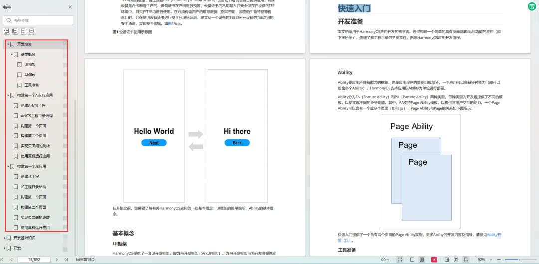
快速入门
- 基本概念
- 构建第一个ArkTS应用
- ……
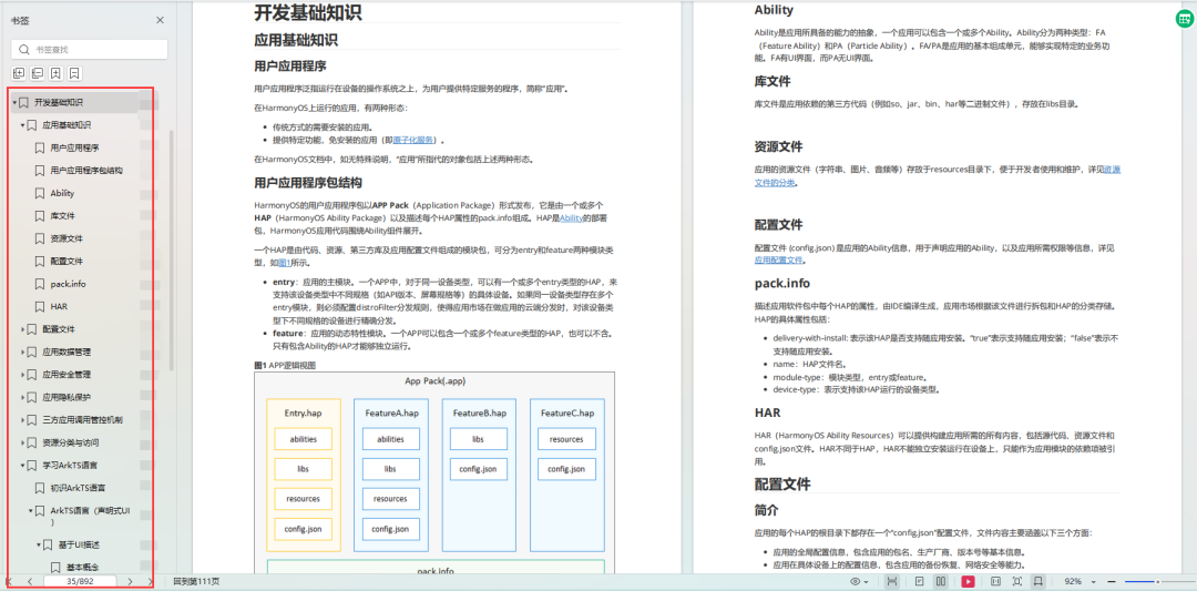
开发基础知识:gitee.com/MNxiaona/733GH
- 应用基础知识
- 配置文件
- 应用数据管理
- 应用安全管理
- 应用隐私保护
- 三方应用调用管控机制
- 资源分类与访问
- 学习ArkTS语言
- ……
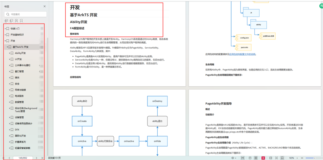
基于ArkTS 开发
- Ability开发
- UI开发
- 公共事件与通知
- 窗口管理
- 媒体
- 安全
- 网络与链接
- 电话服务
- 数据管理
- 后台任务(Background Task)管理
- 设备管理
- 设备使用信息统计
- DFX
- 国际化开发
- 折叠屏系列
- ……
OpenHarmony 开发环境搭建:gitee.com/MNxiaona/733GH
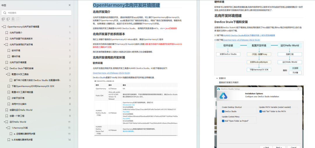
《OpenHarmony源码解析》
- Windows 开发环境的搭建
- Ubuntu 开发环境搭建
- Linux 与 Windows 之间的文件共享
- ……
- 系统架构分析
- 构建子系统
- 启动流程
- 子系统
- 分布式任务调度子系统
- 分布式通信子系统
- 驱动子系统
- ……
OpenHarmony 设备开发学习手册:gitee.com/MNxiaona/733GH

写在最后
- 如果你觉得这篇内容对你还蛮有帮助,我想邀请你帮我三个小忙:
- 点赞,转发,有你们的 『点赞和评论』,才是我创造的动力。
- 关注小编,同时可以期待后续文章ing🚀,不定期分享原创知识。
- 想要获取更多完整鸿蒙最新学习资源,请移步前往小编:
gitee.com/MNxiaona/733GH


 4125
4125

 被折叠的 条评论
为什么被折叠?
被折叠的 条评论
为什么被折叠?
 到【灌水乐园】发言


