


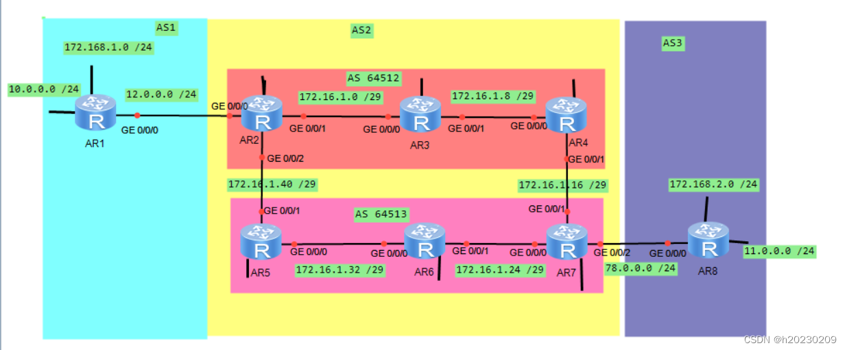
一. 实验拓扑图
二. 实验需求:
1. AS1存在2个环回,一个地址为 192.168.1.0 /24 ,该地址不能在任何协议中宣告,AS3 中存在2个环回,一个地址为 192.168.2.0 /24, 该地址不能在任何协议中宣告,最终要求这两个环回可以互相通讯,AS1的 另一个环回为 10.0.0.0 /24 , AS3 的另一个环回为 11.0.0.0 /24 。
2. 整个AS2的IP地址为 172.16.0.0 /16 ,请合理划分。
3.AS间的骨干链路IP地址随意定制。
4.使用BGP协议让整个网络所有设备的环回可互相访问。
5. 减少路由条目数量,避免环路出现。
三. 实验步骤
步骤一:划分网段
(1)AS1 和 AS2 之前的 R1-R2 划分网段 12.0.0.0 /24 ; AS2 和 AS3 之前的 R7-R8划分网段 78.0.0.0 /24
(2)AS2 基于 172.16.0.0 /16 进行网段划分:
172.16.0.0 /16 -------- 可以划分成 172.16.0.0 /24
骨干链路基于 172.16.1.0 /24 划分----------再将它划分成掩码为 29位的网段:
骨干链路共6个小网段,给其分配出6个网段即可
172.16.1.0 /29 --------------R2--R3
172.16.1.8 /29 ---------------R3--R4
172.16.1.16 /29 --------------R4--R7
172.16.1.24 /29 --------------R6--R7
172.16.1.32 /29 ---------------R5--R6
172.16.1.40 /29 ---------------R2--R5
R2-R7的环回分别划分为:
172.16.2.0 /24 ------------------ R2环回
172.16.3.0 /24 ------------------ R3环回
172.16.4.0 /24 ------------------ R4环回
172.16.5.0 /24 ------------------ R5环回
172.16.6.0 /24 ------------------ R6环回
172.16.7.0 /24 ------------------ R7环回
步骤二: R1-R8 分别配置IP地址:
R1 ip 配置如下:
[R1-GigabitEthernet0/0/0]ip add 12.0.0.1 24
[R1-LoopBack0]ip add 192.168.1.1 24
[R1-LoopBack1]ip add 10.0.0.1 24
R2 ip 配置如下:
[R2-GigabitEthernet0/0/0]ip add 12.0.0.2 24
[R2-GigabitEthernet0/0/1]ip add 172.16.1.1 29
[R2-GigabitEthernet0/0/2]ip add 172.16.1.41 29
[R2-LoopBack0]ip add 172.16.2.1 24
R3 ip 配置如下:
[R3-GigabitEthernet0/0/0]ip add 172.16.1.2 29
[R3-GigabitEthernet0/0/1]ip add 172.16.1.9 29
[R3-LoopBack0]ip add 172.16.3.1 24
R4 ip 配置如下:
[R4-GigabitEthernet0/0/0]ip add 172.16.1.10 29
[R4-GigabitEthernet0/0/1]ip add 172.16.1.17 29
[R4-LoopBack0]ip add 172.16.4.1 24
R5 ip 配置如下:
[R5-GigabitEthernet0/0/1]ip add 172.16.1.42 29
[R5-GigabitEthernet0/0/0]ip add 172.16.1.33 29
[R5-LoopBack0]ip add 172.16.5.1 24
R6 ip 配置如下:
[R6-GigabitEthernet0/0/0]ip add 172.16.1.34 29
[R6-GigabitEthernet0/0/1]ip add 172.16.1.25 29
[R6-LoopBack0]ip add 172.16.6.1 24
R7 ip 配置如下:
[R7-GigabitEthernet0/0/0]ip add 172.16.1.26 29
[R7-GigabitEthernet0/0/1]ip add 172.16.1.18 29
[R7-GigabitEthernet0/0/2]ip add 78.0.0.1 24
[R7-LoopBack0]ip add 172.16.7.1 24
R8 ip 配置如下:
[R8-GigabitEthernet0/0/0]ip add 78.0.0.2 24
[R8-LoopBack0]ip add 192.168.2.1 24
[R8-LoopBack1]ip add 11.0.0.1 24
步骤三: 运行BGP协议,建立在 整个网络可达的情况下:
(1)AS2 先运行ospf协议,使得网络可达
[R2]ospf 1 router-id 2.2.2.2
[R2-ospf-1-area-0.0.0.0]network 172.16.0.0 0.0.255.255
[R3]ospf 1 router-id 3.3.3.3
[R3-ospf-1-area-0.0.0.0]network 172.16.0.0 0.0.255.255
[R4]ospf 1 router-id 4.4.4.4
[R4-ospf-1-area-0.0.0.0]network 172.16.0.0 0.0.255.255
[R5]ospf 1 router-id 5.5.5.5
[R5-ospf-1-area-0.0.0.0]network 172.16.0.0 0.0.255.255
[R6]ospf 1 router-id 6.6.6.6
[R6-ospf-1-area-0.0.0.0]network 172.16.0.0 0.0.255.255
[R7]ospf 1 router-id 7.7.7.7
[R7-ospf-1-area-0.0.0.0]network 172.16.0.0 0.0.255.255
(2)所有设备 运行BGP 协议
[R1]bgp 1
[R1-bgp]router-id 1.1.1.1
[R1-bgp]peer 12.0.0.2 as-number 2
[R2]bgp 64512
[R2-bgp]router-id 2.2.2.2
[R2-bgp]confederation peer-as 64513
[R2-bgp]peer 12.0.0.1 as-number 1
[R2-bgp]peer 172.16.3.1 as-number 64512
[R2-bgp]peer 172.16.3.1 connect-interface l 0
[R2-bgp]peer 172.16.5.1 as-number 64513
[R2-bgp]peer 172.16.5.1 connect-interface l 0
[R2-bgp]peer 172.16.5.1 ebgp-max-hop
[R3]bgp 64512
[R3-bgp]router-id 3.3.3.3
[R3-bgp]confederation id 2
[R3-bgp]peer 172.16.2.1 as-number 64512
[R3-bgp]peer 172.16.2.1 connect-interface l 0
[R3-bgp]peer 172.16.4.1 as-number 64512
[R3-bgp]peer 172.16.4.1 connect-interface l 0
[R4]bgp 64512
[R4-bgp]router-id 4.4.4.4
[R4-bgp]confederation id 2
[R4-bgp]confederation peer-as 64513
[R4-bgp]peer 172.16.3.1 as-number 64512
[R4-bgp]peer 172.16.3.1 connect-interface l 0
[R4-bgp]peer 172.16.7.1 as-number 64513
[R4-bgp]peer 172.16.7.1 connect-interface l 0
[R4-bgp]peer 172.16.7.1 ebgp-max-hop
[R5]bgp 64513
[R5-bgp]router-id 5.5.5.5
[R5-bgp]confederation id 2
[R5-bgp]confederation peer-as 64512
[R5-bgp]peer 172.16.2.1 as-number 64512
[R5-bgp]peer 172.16.2.1 connect-interface l 0
[R5-bgp]peer 172.16.2.1 ebgp-max-hop
[R5-bgp]peer 172.16.6.1 as-number 64513
[R5-bgp]peer 172.16.6.1 connect-interface l 0
[R6]bgp 64513
[R6-bgp]router-id 6.6.6.6
[R6-bgp]confederation id 2
[R6-bgp]peer 172.16.5.1 as-number 64513
[R6-bgp]peer 172.16.5.1 connect-interface l 0
[R6-bgp]peer 172.16.7.1 as-number 64513
[R6-bgp]peer 172.16.7.1 connect-interface l 0
[R7]bgp 64513
[R7-bgp]router-id 7.7.7.7
[R7-bgp]confederation id 2
[R7-bgp]confederation peer-as 64512
[R7-bgp]peer 172.16.6.1 as-number 64513
[R7-bgp]peer 172.16.6.1 connect-interface l 0
[R7-bgp]peer 172.16.4.1 as-number 64512
[R7-bgp]peer 172.16.4.1 connect-interface l 0
[R7-bgp]peer 172.16.4.1 ebgp-max-hop
[R7-bgp]peer 78.0.0.2 as-number 3
[R8]bgp 3
[R8-bgp]router-id 8.8.8.8
[R8-bgp]peer 78.0.0.1 as 2
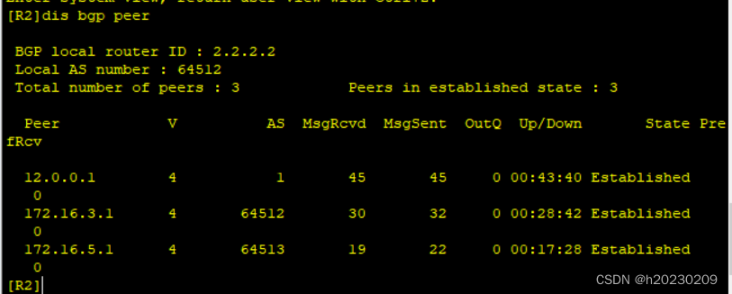
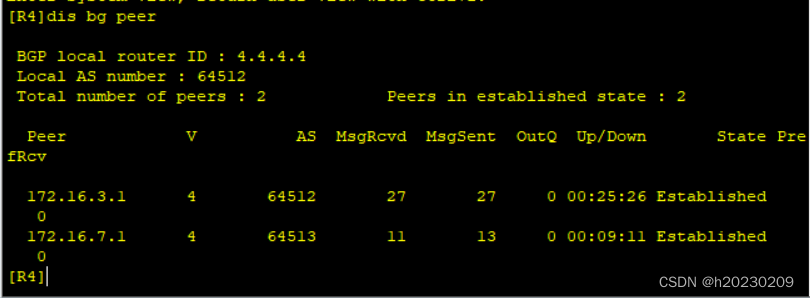
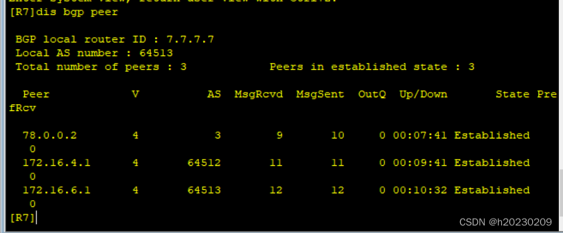
查看bgp 邻居建立情况:
(3)AS1 和 AS3 ,分别发布路由。
(3.1)AS1 中 R1发布路由
[R1]bgp 1
[R1-bgp]network 10.0.0.0 24
指定R3作为路由反射器,R2作为 客户
[R3]bgp 64512
[R3-bgp]peer 172.16.2.1 reflect-client
指定R6作为路由反射器,R7作为 客户
[R6]bgp 64513
[R6-bgp]peer 172.16.7.1 reflect-client
因为AS-BY-AS,所以需要将 下一跳 改为本地地址:
[R2]bgp 64512
[R2-bgp]peer 172.16.3.1 next-hop-local
[R2-bgp]peer 172.16.5.1 next-hop-local
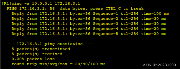
查看R4、R7是否收到R1发布的路由:
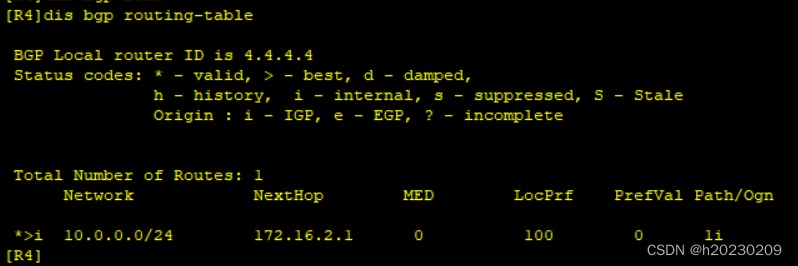
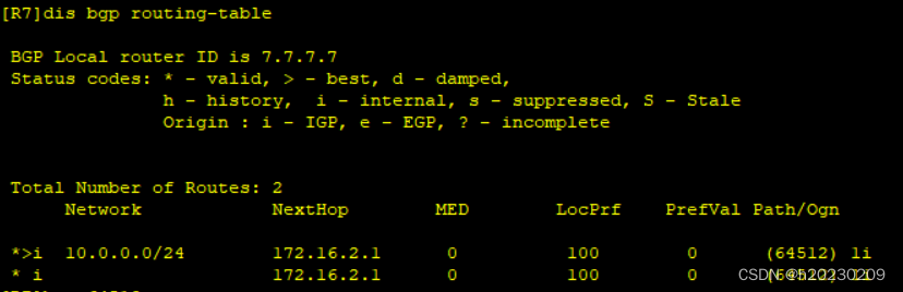
(3.2)AS3 中 R8 发布路由
[R8]bgp 3
[R8-bgp]network 11.0.0.0 24
[R7]bgp 64513
[R7-bgp]peer 172.16.6.1 next-hop-local
[R7-bgp]peer 172.16.4.1 next-hop-local
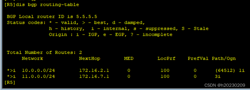
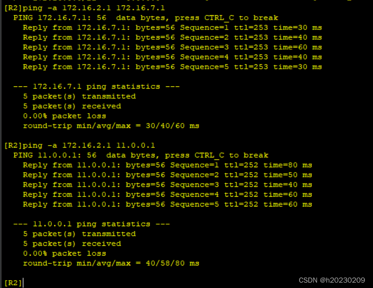
查看 R5、R2 是否获得R8发布的路由:

(4)AS2 中 聚合路由 ----- 减少路由条路,需要在R2 和 R7 边界设备上聚合,然后发布路由。
AS2中,R2-R7的环回,汇总后的网段为: 172.16.0.0 /21 , 写出指向该汇总网段空接口的路由,然后将该路由发布出去。
[R2]ip route-static 172.16.0.0 21 null 0
[R2]bgp 64512
[R2-bgp]network 172.16.0.0 21
[R7]ip route-static 172.16.0.0 21 null 0
[R7]bgp 64513
[R7-bgp]network 172.16.0.0 21
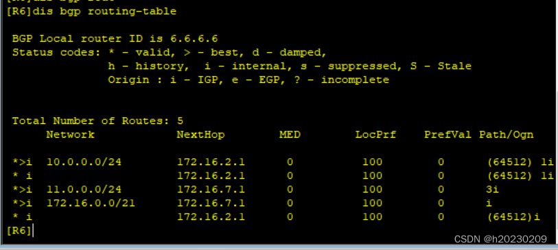
查看bgp 已发布的路由信息:
测试环回是否都可 ping 通(除了 R1 和 R8 为宣告的环回外):
(5) 所有设备环回均可访问。
R1 和 R8 ,分别有1个环回 都未宣告,现要 使环回均可访问,在当前BGP协议下,用 gre封装,建立隧道。 给隧道网段 192.168.3.0 /24 .
[R1]int t 0/0/0
[R1-Tunnel0/0/0]ip add 192.168.3.1 24
[R1-Tunnel0/0/0]tunnel-protocol gre
[R1-Tunnel0/0/0]source 10.0.0.1
[R1-Tunnel0/0/0]destination 11.0.0.1
[R1]ip route-static 192.168.2.0 24 192.168.3.2
[R8]int t 0/0/0
[R8-Tunnel0/0/0]ip add 192.168.3.2 24
[R8-Tunnel0/0/0]tunnel-protocol gre
[R8-Tunnel0/0/0]source 11.0.0.1
[R8-Tunnel0/0/0]destination 10.0.0.1
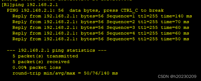
[R8]ip route-static 192.168.1.0 24 192.168.3.1
用R1 ping R8的环回,可以拼通:


 726
726


 被折叠的 条评论
为什么被折叠?
被折叠的 条评论
为什么被折叠?
 到【灌水乐园】发言


