


目录
(2)获取图层表和图层记录(就是AutoCAD里的图层,如图层0)
1 环境配置
1.1安装AutoCAD
注意,由于低版本的AutoCAD无法打开高版本的AutoCAD图纸,因此团队合作开发时最好和团队成员的AutoCAD版本保持一致。个人学习建议使用最新版AutoCAD2024。
1.2 建立AutoCAD二次开发项目
开发平台:Visual Studio2022(简称VS2022)
开发语言:C#
项目模板:类库(.NET Framewoek)
1.2.1 新建VS项目
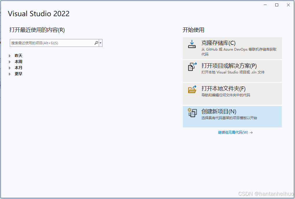
(1)打开VS2022,点击创建新项目
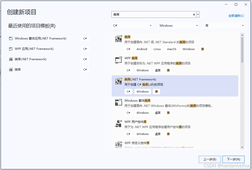
(2)搜索:类库,找到并选中:类库(.NET Framewoek)
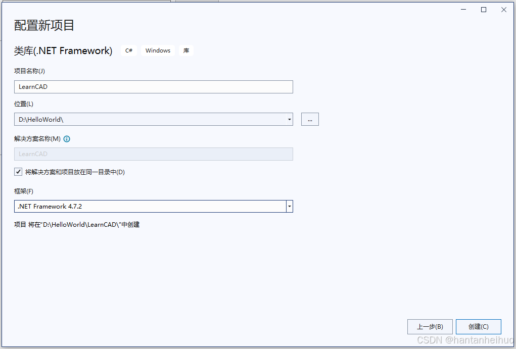
(3)点击下一步,设置项目名称、位置(不建议使用中文路径)、框架。
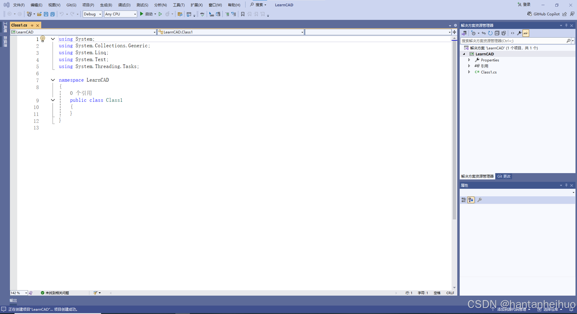
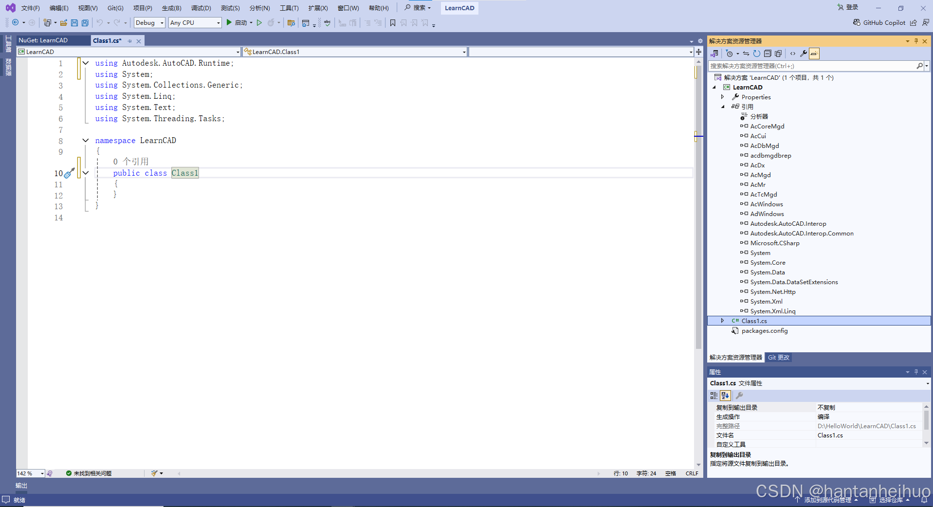
(4)点击创建,VS2022自动打开项目,界面如下:
1.2.2 添加AutoCAD开发包
(1)在解决方案资源管理器界面内,选中项目名称LearnCAD,点击鼠标右键
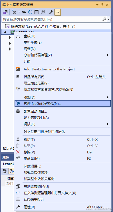
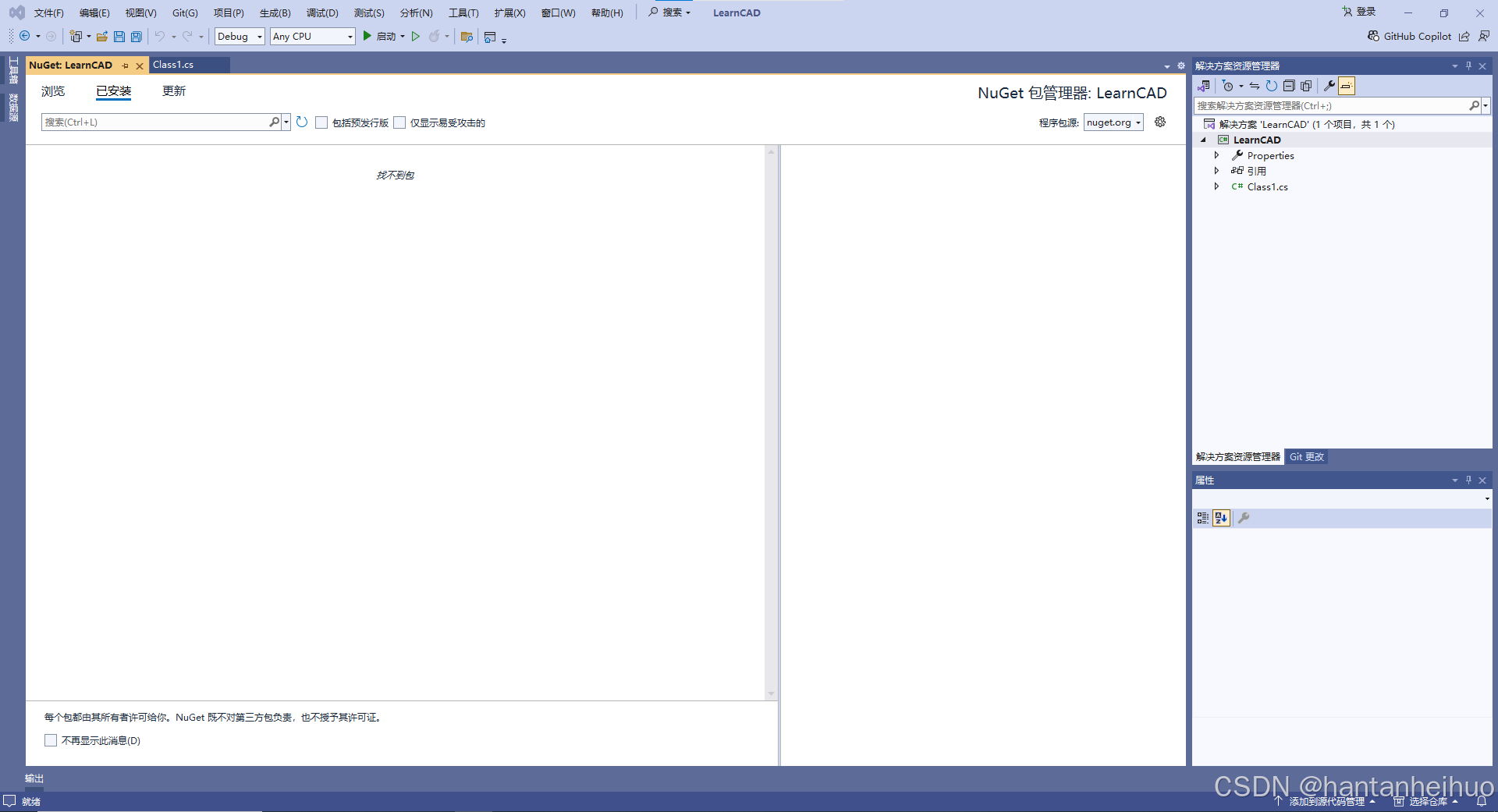
(2)点击管理NuGet程序包,进入NuGet包管理器界面
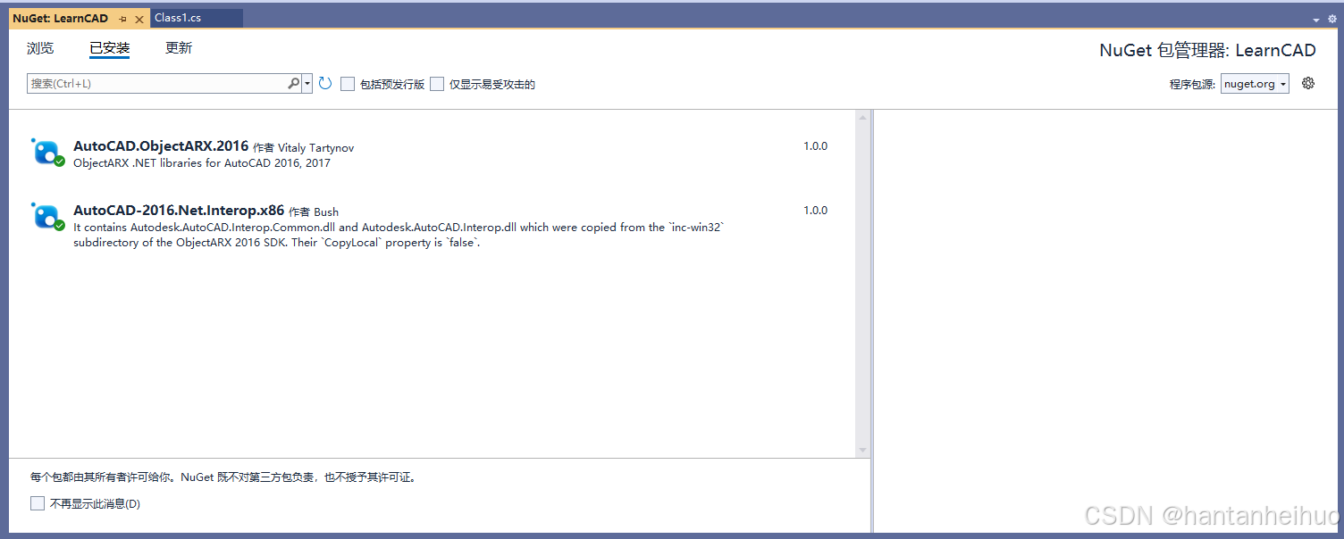
(3)点击浏览标签,输入cad2016,安装如下开发包(选中包后点击右侧的安装按钮):
AutoCAD.ObjectARX.2016 、AutoCAD-2016.Net.Interop.x86
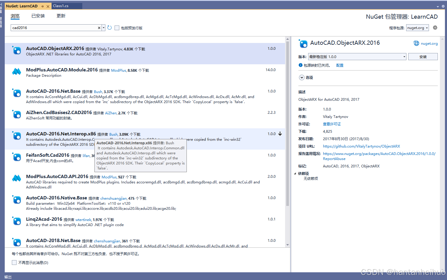
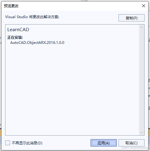
中间弹出预览更改界面,点击应用即可
(4)查看安装好的开发包:点击已安装标签,并清空搜索框内容即可
或者在解决方案资源管理器界面,查看引用是否更新。
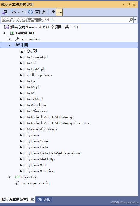
若无误,那么恭喜,一个简单的AutoCAD类库开发项目已经建立成功!
2 快速上手
2.1 实现AutoCAD命令接口
2.1.1 添加接口
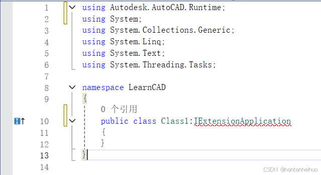
(1)打开作为接口的类Class1
(2)在类名Class1后面添加接口代码 :IExtensionApplication
2.1.2 实现接口
(1)鼠标光标移动到报错位置,点击显示可能的修补程序
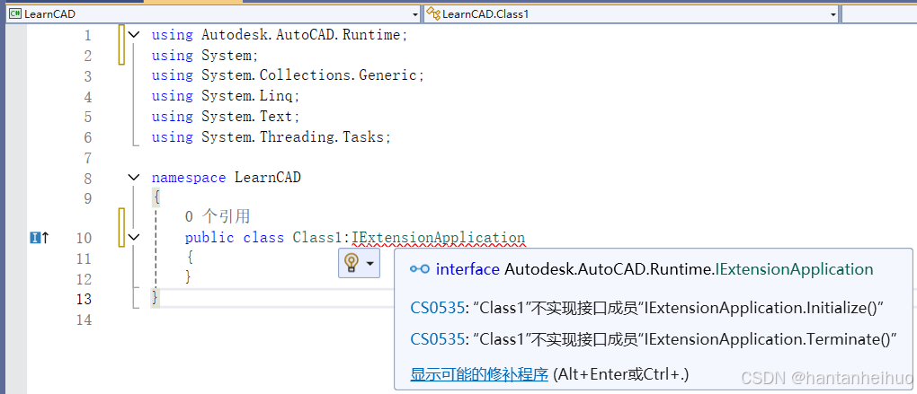
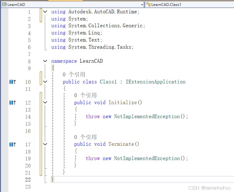
(2)点击实现接口,系统自动生成两个函数 Initialize()、Terminate()
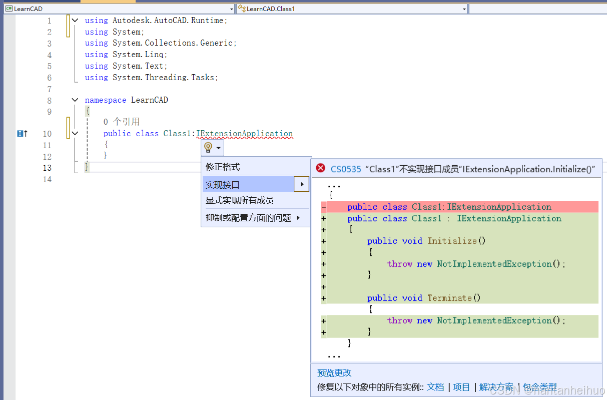
(3)生成的代码如下,但经测试,这种接口不能直接使用,还需要对代码做些调整。
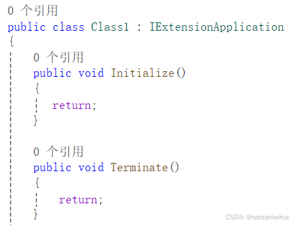
(4)调整好的代码如下,将原来的throw new NotImplementedException() 替换为return 即可。
2.2 自定义CAD命令
(1)在作为接口的类Class1中,添加如下命令
[CommandMethod("HelloWorld")]
public void HelloWorld()
{
    MessageBox.Show("Hello,World!");
}(2)Class1中的全部代码如下:
public class Class1 : IExtensionApplication
{
    public void Initialize()
    {
       return;
    }

    public void Terminate()
    {
        return;
    }
    [CommandMethod("HelloWorld")]
    public void HelloWorld()
    {
        MessageBox.Show("Hello,World!");
    }
}(2)若MessageBox报错标红,则将鼠标光标移动到报错处,点击显示可能的修补程序
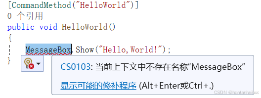
然后选择using System.Windows;
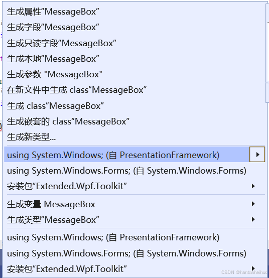
此时错误消失,上方出现代码using System.Windows;
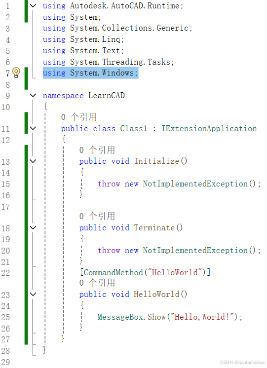
至此,已经自定义了一个简单的CAD命令。
说明:字符串 "HelloWorld" 可替换为其它自定义命令,下面的函数名 HelloWorld() 也可按照喜好进行设置。
2.3 使用自定义命令
2.3.1 输出类库
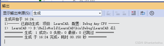
(1)在生成菜单中找到生成解决方案,点击确定
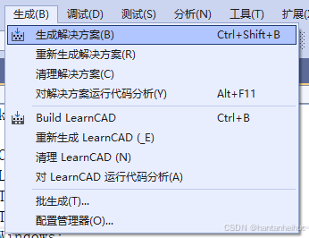
(2)在输出界面查看输出信息,可以看到生成了一个类库(.dll)文件,可在AutCAD中加载使用
2.3.2 加载自定义插件
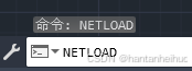
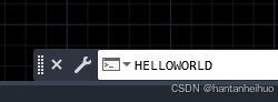
(1)打开AutoCAD,在下方命令框中输入命令:NetLoad,点击回车
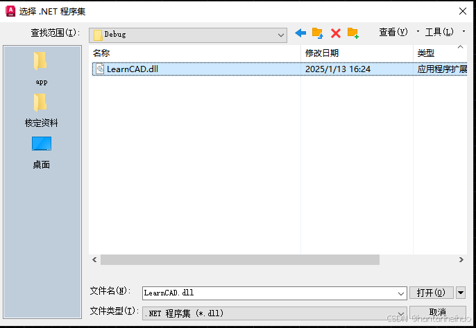
(2)找到自己项目中生成的类库(.dll)文件,点击打开,默认在项目文件夹的"bin\debug\"里面。
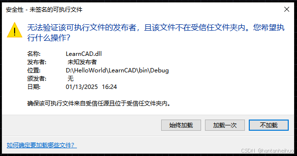
(3)弹出安全性-未签名的可执行文件对话框,选择加载一次或始终加载(个人测试的两种效果好像相同)。至此,插件加载完毕。
2.3.3 使用自定义命令
(1)在下方命令框中输入之前的自定义命令:HelloWorld,输入字母时不用在意大小写,CAD会自动设为大写。
(2)点击Enter键或者空格键确认,弹出Hello,World!窗口
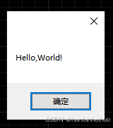
至此,恭喜,你已经实现了在AutoCAD中使用自定义命令!
3基础功能
3.1 AutoCAD文档
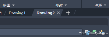
3.1.1 获取当前文档
当前文档就是CAD目前正在使用的文档,如Drawing2就是当前文档。
代码如下:
Document doc = Application.DocumentManager.MdiActiveDocument;//获取当前文档
Document doc = Application.DocumentManager.MdiActiveDocument;若Application报错,则在上方引用中添加代码:
using Application = Autodesk.AutoCAD.ApplicationServices.Application;3.1.2 获取文档的数据库
(1)获取当前文档的数据库
 Document doc = Application.DocumentManager.MdiActiveDocument;//获取当前文档
Database db = doc.Database;//获取文档的数据库(2)获取其他文档的数据库
第一种:DWG文档
string filePath = "D:\\HelloWorld\\LearnCAD\\测试.dwg";
using (Database database = new Database(false, true))
{
    database.ReadDwgFile(filePath, System.IO.FileShare.Read, false, null);//读取DWG文件
    database.CloseInput(true); //关闭文件
}第二种:DXF文档
string filePath = "D:\\HelloWorld\\LearnCAD\\测试.dxf";
using (Database database = new Database(false, true))
{
    database.DxfIn(filePath, "");//读取DXF文件
    database.CloseInput(true);//关闭文件
}
3.1.3 获取当前文档的编辑器
代码如下,这三行代码经常一起出现,属于是固定格式,建议牢记。
 Document doc = Application.DocumentManager.MdiActiveDocument;//获取当前文档
 Database db = doc.Database;//获取文档的数据库
 Editor ed=doc.Editor;//获取文档的编辑器
3.1.4 打开文件夹中的DWG文档
Open重载的第二个参数:是否以只读方式打开文档
string filePath = "D:\\HelloWorld\\LearnCAD\\测试.dwg";
DocumentCollection docManager = Application.DocumentManager;
Document doc1 = docManager.Open(filePath);//默认方式打开
Document doc2 = docManager.Open(filePath,false);//是否以只读方式打开:false
3.1.5 保存文档
(1)保存当前文档(不关闭文档)
第一种,相当于在CAD的命令框中手动输入命令:QSave
 Document doc = Application.DocumentManager.MdiActiveDocument;
 Editor ed = doc.Editor;
 ed.Command("QSave");
(2)另存当前文档
第一种,调用SaveAs函数:
 string filePath1 = "D:\\HelloWorld\\LearnCAD\\测试1.dwg";
 Document doc = Application.DocumentManager.MdiActiveDocument;
 Database db = doc.Database;
db.SaveAs(filePath1, DwgVersion.Current);//另存文档,DwgVersion.Current:当前版本第二种,发送命令SaveAs,相当于在CAD的命令框中手动输入命令:SaveAs
 Document doc = Application.DocumentManager.MdiActiveDocument;
 Editor ed = doc.Editor;
ed.Command("SaveAs");![]()
3.2 AutoCAD事务
AutoCAD事务(Transaction)是AutoCAD .NET API中的一种机制,用于管理对图形数据库的修改。它允许开发者将一系列操作封装为一个事务,确保这些操作要么全部成功,要么全部失败,从而维护数据的一致性。流程大致为:获取文档--获取文档的数据库--开启事务--修改操作(添加、删除、修改等等)--提交事务。
开启事务:Transaction trans = db.TransactionManager.StartTransaction()
各种操作:增、删、改、查询等等
提交事务:trans.Commit()
撤销事务: trans.Abort()
3.2.1 向当前文档中添加一条线
 Document doc = Application.DocumentManager.MdiActiveDocument;//固定格式:获取当前文档
 Database db = doc.Database;//获取当前数据库
 using (Transaction trans = db.TransactionManager.StartTransaction())//设置事务
 {

     BlockTableRecord modelSpace = (BlockTableRecord)trans.GetObject(db.CurrentSpaceId, OpenMode.ForWrite); // 以写入方式打开模型空间

     Point3d point1 = new Point3d(0, 0, 0);
     Point3d point2 = new Point3d(0, 1, 0);
     Line line = new Line(point1, point2);//建立一条线

     modelSpace.AppendEntity(line);//把线添加到模型空间
     trans.AddNewlyCreatedDBObject(line, true);//把线添加到事务中

     trans.Commit(); // 提交事务
 }
3.2.2 遍历当前文档中所有实体的类型
(1)实体 Entity
实体:包括点、线、面、注释文字、块等等。
实体id存储在块表记录:BlockTableRecord 中,通过实体id可以获取到实体。
(2)实现过程
这是我在空白文档中绘制的两个实体:圆和矩形

运行下面代码
 Document doc = Application.DocumentManager.MdiActiveDocument;//固定格式:获取当前文档
 Database db = doc.Database;//获取当前数据库
 Editor ed= doc.Editor;
 string name = null;
 using (Transaction trans = db.TransactionManager.StartTransaction())//设置事务
 {

     BlockTableRecord modelSpace = (BlockTableRecord)trans.GetObject(db.CurrentSpaceId, OpenMode.ForRead); // 以只读方式打开模型空间

     foreach (ObjectId id in modelSpace)
     {
         Entity entity = trans.GetObject(id, OpenMode.ForWrite) as Entity;//获取实体
         name += entity.GetType()+"\r\n";
     }
     ed.WriteMessage(name);
     trans.Commit(); // 提交事务

 }
结果如下:

3.2.3 删除实体
用实体自带的擦除方法Erase()来将实体删除,这里是把当前模型空间里的实体全部删除了,实际可根据需要删除特定的实体,比如只删除线实体等等
Document doc = Application.DocumentManager.MdiActiveDocument;//固定格式:获取当前文档
Database db = doc.Database;//获取当前数据库
Editor ed = doc.Editor;

using (Transaction trans = db.TransactionManager.StartTransaction())//设置事务
{
    BlockTableRecord modelSpace = (BlockTableRecord)trans.GetObject(db.CurrentSpaceId, OpenMode.ForRead); // 以只读方式打开模型空间
    foreach (ObjectId id in modelSpace)
    {
        Entity entity = trans.GetObject(id, OpenMode.ForWrite) as Entity;//获取实体
        entity.Erase();
    }
    trans.Commit(); // 提交事务
}
3.3 AutoCAD对象
3.3.1层次划分
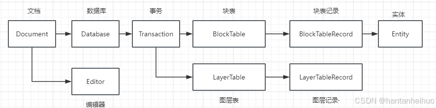
3.3.2 获取对象
此处的对象指的是上图事务之后的对象,如块表、块表记录、图层表、图层记录、实体。获取对象需要提供对象id(ObjectId),然后通过事务获取。
(1)获取块表和当前块表记录(有时也叫模型空间)
方法1:直接通过数据库提供的属性字段 CurrentSpaceId 来获取对象id,更推荐
方法2:需要先提供块表记录的名称,然后用块表索引(类似于数组索引)获取id,不推荐
(直接运行代码会报错,记得把方法2删除或注释掉,这里只供学习使用)
Document doc = Application.DocumentManager.MdiActiveDocument;//固定格式:获取当前文档
Database db = doc.Database;//获取当前数据库
Editor ed = doc.Editor;

using (Transaction trans = db.TransactionManager.StartTransaction())//设置事务
{
    BlockTable blockTable = (BlockTable)trans.GetObject(db.BlockTableId, OpenMode.ForWrite); // 以写入方式打开块表


    BlockTableRecord blockTableRecord = (BlockTableRecord)trans.GetObject(db.CurrentSpaceId, OpenMode.ForWrite);//方法1:以写入方式打开当前块表记录(通过数据库db打开):推荐

    string blockTableRecord_name = "";//这里需要给出目标块表记录的名字Name字符串
    BlockTableRecord blockTableRecord2 = (BlockTableRecord)trans.GetObject(blockTable[blockTableRecord_name], OpenMode.ForWrite);//方法2:以写入方式打开当前块表记录(通过块表打开):不推荐
}
但是可以遍历块表中的块表记录的名称,附上代码和结果
string name = null;
foreach (ObjectId blockId in blockTable)
{
    // 获取BlockTableRecord对象
    BlockTableRecord blockRecord = (BlockTableRecord)trans.GetObject(blockId, OpenMode.ForRead);
    name += blockRecord.Name+"\r\n";
}
ed.WriteMessage(name);![]()
(2)获取图层表和图层记录(就是AutoCAD里的图层,如图层0)
方法1:获取当前图层,通过数据库提供的属性字段Clayer直接获取id
方法2:获取特定图层,通过图层名称索引获取id
最后:遍历所有图层表中的图层,附上运行结果
Document doc = Application.DocumentManager.MdiActiveDocument;//固定格式:获取当前文档
Database db = doc.Database;//获取当前数据库
Editor ed = doc.Editor;

using (Transaction trans = db.TransactionManager.StartTransaction())//设置事务
{
    LayerTable layerTable= (LayerTable)trans.GetObject(db.LayerTableId, OpenMode.ForWrite);//获取图层表

    LayerTableRecord layerRecord = (LayerTableRecord)trans.GetObject(db.Clayer, OpenMode.ForWrite);//方法1:获取当前图层

    string layerName = "0";
    LayerTableRecord layerRecord2 = (LayerTableRecord)trans.GetObject(layerTable[layerName], OpenMode.ForWrite);//方法2:获取特定图层

    string LayerNames = null;
    foreach(ObjectId id in layerTable)//遍历图层id
    {
        LayerTableRecord layer = (LayerTableRecord)trans.GetObject(id, OpenMode.ForWrite);
        LayerNames += layer.Name + "\r\n";
    }
    ed.WriteMessage(LayerNames);
}![]()
(3)获取实体
前面有 3.2.2 遍历当前文档中所有实体的类型,此处只附上核心代码,其中第二种类型转换方式更常用。
 Entity entity = trans.GetObject(id, OpenMode.ForWrite) as Entity;//获取实体
 Entity entity2 = (Entity)trans.GetObject(id, OpenMode.ForWrite);//获取实体
3.3.3 实体分类汇总
实体包括:线、块、组、图案填充等等(以后遇到会继续补充),点类型并不属于实体范畴,但为了更好理解,把点类型暂时也放在该板块。
另外,很多属性或方法是继承来的,如Color、Layer、ObjectID等等。因此按照子类或父类,分别介绍各自的方法,有些继承方法需要到父类中查找。
3.3.3.1 点
(1)2维点:Point2d
构造
Point2d point1 = new Point2d(0, 0);方法
RotateBy(double angle,Point2d point):获取绕point逆时针旋转angle(弧度)后的点坐标,不改变原来的坐标
Add(Vector2d vector):获取向量变换后的点坐标,相当于坐标后面直接加上vector,不改变原来的点坐标
DivideBy(double value):获取(x,y)除以value后的点坐标,不改变原来的点坐标
ScaleBy(double value,Point2d point):获取关于点point进行value倍缩放(距离变为原来的value倍)后的点坐标,不改变原来点的坐标
Point2d point1 = new Point2d(0, 0);
double point_X = point1.X;//获取点的X坐标,属性只读
double point_Y = point1.Y;//获取点的Y坐标,属性只读

Point2d point2 = point1.RotateBy(90 * Math.PI / 180, new Point2d(0, 1));//获取point1 绕(0,1)逆时针旋转90°后的点坐标,不改变原来点的坐标,结果为(1,1)

Point2d point3 = point1.Add(new Vector2d(1, 1));//获取点point1 加上向量(1,1)后的点坐标,不改变原来点的坐标,和下面的方法等效,结果为(1,1)
Point2d point3_2 = point1 + new Vector2d(1, 1);//获取点point1 加上向量(1,1)后的点坐标,不改变原来点的坐标,和上面的方法等效,结果为(1,1)

Point2d point4 = point1.DivideBy(2); //获取point1 坐标均除以2后的点坐标,不改变原来点的坐标,若除以0,结果为(NaN,NaN)

Point2d point5 = point1.ScaleBy(2, new Point2d(0, 1));//获取point1 坐标关于点(0,1)进行2倍缩放(距离变为原来的2倍)后的点坐标,不改变原来点的坐标,结果为(0,-1)
TransformBy(Matrix2d matrix):获取矩阵变化后的点坐标,不改变原来的点坐标
这里的矩阵也很特殊,共有9个元素。计算过程也比较特殊,经测试后得出的计算过程为:
Xnew=(1*X+2*Y+3)/(7*X+8*Y+9)
Ynew=(4*X+5*Y+6)/(7*X+8*Y+9)
Point2d point1 = new Point2d(0, 0);
double[] doubles = new double[9] { 1, 2, 3, 4, 5, 6, 7, 8, 9 };
Matrix2d matrix = new Matrix2d(doubles);//矩阵,第一行为{1,2,3},第二行为{4,5,6},第三行为{7,8,9}
Point2d point6 = point1.TransformBy(matrix);//结果为(0.333333...,0.666666...)
Mirror(Line2d line):获取点关于线镜像后的点坐标,不改变原来的点坐标
Line2d line = new Line2d(new Point2d(1, -1), new Point2d(1, 1));//构造一条2d线line
Point2d point7 = point1.Mirror(line);//获取点point1 关于2d线line的镜像点,不改变原来点的坐标,结果为(2,0)
Equals(object obj):判断点和对象obj 是否相等,类型相同and值也相同时为true,否则为false
IsEqualTo(Point2d a):判断点和点a是否是相等的(距离为0时为true,否则为false)
IsEqualTo(Point2d a, Tolerance tolerance):判断点和点a是否是相等的(在容差允许范围内时为true,否则为false)
Tolerance tolerance = new Tolerance(0,1);//设置容差,参数为(double equalVector,double equalPoint),不给参数时默认都为0,equalPoint为两点距离误差。
备注:在此案例中的容差的第2个参数才有用,指的是两点间的距离<=1时为true,否则为false
Point2d point1_1 = new Point2d(0, 0);
bool equals = point1.Equals(point1_1);//判断点point1 和point1_1是否相等(类型相同and值也相同),结果为true

bool isEqualsTo_1 =point1.IsEqualTo(point1_1);//判断point1和point1_1是否相等
Tolerance tolerance = new Tolerance(0,1);//设置容差
bool isEqualsTo_2 = point1.IsEqualTo(point1_1, tolerance);//判断point1和point1_1在容差范围内是否相等,结果为trueGetAsVector():获取点的对应向量
Vector2d vector= point1.GetAsVector();//获取点的对应向量GetDistanceTo(Point2d a):获取两点间的距离
double distance=point1.GetDistanceTo(point1_1);//获取两点间的距离GetVectorTo(Point2d a):获取点到点a的向量
Vector2d vector2=point1.GetVectorTo(new Point2d(1,1));//获取从point1到点(1,1)的向量Subtract(Vector2d vector):获取点减去向量vector后的点坐标,和第二种计算方式等效
Point2d point8 = point1.Subtract(new Vector2d(1, 1));//结果为(-1,-1)
Point2d point8_2 = point1 - new Vector2d(1, 1);//结果为(-1,-1)GetType():获取点的类型,可通过字符串获取到类型名称
Type type= point1.GetType();
string typename = point1.GetType().Name;//结果为"Point2d"
string typename2 = point1.GetType()+"";//结果为"Autodesk.AutoCAD.Geometry.Point2d"
(2)3维点:Point3d
构造
Point3d point3d=new Point3d(0,0,0);方法
以下所有代码中的point3d为同一个点,坐标为(0,0,0)
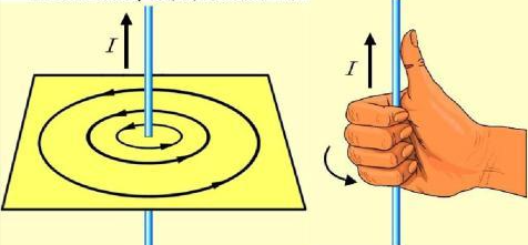
RotateBy(double angle, Vector3d vector, Point3d centerPoint):参数分别为:旋转角度、旋转轴、旋转中心。旋转方向为旋转轴的逆时针方向,支持右手螺旋定则,可参考电磁场中的右手螺旋。
Point3d point3d_2= point3d.RotateBy(90*Math.PI/180, new Vector3d(0, 0, 1), new Point3d(0, 1, 0));//将点point3d绕着点(0,1,0)旋转90°,旋转轴为向量(0,0,1),结果为(1,1,0)Add(Vector3d value):获取向量变换后的点坐标,相当于坐标后面直接加上vector,不改变原来的点坐标
Point3d point3d_3 = point3d.Add(new Vector3d(1, 1, 1));//获取点point3d加上向量(1,1,1)后的点坐标,不改变原来的点坐标,结果为(1,1,1)
Point3d point3d_4 = point3d + new Vector3d(1, 1, 1);//和上面的方法等效
DivideBy(double value):获取(x,y,z)除以value后的点坐标,不改变原来的点坐标
Point3d point3d_5 = point3d.DivideBy(2);//获取(x,y,z)除以2后的点坐标,不改变原来的点坐标ScaleBy(double value,Point3d point):获取关于点point进行value倍缩放(距离变为原来的value倍)后的点坐标,不改变原来点的坐标
Point3d point3d_6 = point3d.ScaleBy(2, new Point3d(0, 1, 0));//获取关于点(0,1,0)进行2倍缩放(距离变为原来的2倍)后的点坐标,结果为(0,-1,0)TransformBy(Matrix3d leftSide):获取矩阵变化后的点坐标,不改变原来的点坐标
计算过程经测试为:
Xnew=(1*X+2*Y+3*Z+4)/(13*X+14*Y+15*Z+16)
Ynew=(5*X+6*Y+7*Z+8)/(13*X+14*Y+15*Z+16)
Xnew=(9*X+10*Y+11*Z+12)/(13*X+14*Y+15*Z+16)
double[] data = new double[16] { 1, 2, 3, 4, 5, 6, 7, 8, 9, 10, 11, 12, 13, 14, 15, 16 };
Matrix3d matrix = new Matrix3d(data);
Point3d point3d_7 = point3d.TransformBy(matrix);//结果为(0.25,0.5,0.75)
Mirror(Plane plane):获取点关于面plane的镜像点
Plane plane = new Plane(new Point3d(0,0,1),new Vector3d(0,0,1));//定义一个面对象,基准点为(0,0,1),法向量为(0,0,1)
Point3d point3d_8 = point3d.Mirror(plane);//结果为(0,0,2)
Equals(object obj):判断点和对象obj 是否相等,类型相同and值也相同时为true,否则为false
IsEqualTo(Point3d a):判断点和点a是否是相等的(距离为0时为true,否则为false)
IsEqualTo(Point3d a, Tolerance tolerance):判断点和点a是否是相等的(在容差允许范围内时为true,否则为false)
Tolerance tolerance = new Tolerance(0,1);//设置容差,参数为(double equalVector,double equalPoint),不给参数时默认都为0,equalPoint为两点距离误差。
备注:在此案例中的容差的第2个参数才有用,指的是两点间的距离<=1时为true,否则为false
bool Equal = point3d.Equals(new Point3d(0,0,1));//结果为false
bool isEqual = point3d.IsEqualTo(new Point3d(0, 0, 1));//结果为false
Tolerance tolerance = new Tolerance(0,1);//定义一个容差:距离<=1时满足条件
bool isEquanl_2=point3d.IsEqualTo(new Point3d(0,0,1), tolerance);//结果为trueGetAsVector():获取点的对应向量
GetVectorTo(Point3d a):获取点到点a的向量
Vector3d vector = point3d.GetAsVector();//获取原点到point3d的向量,结果为(0,0,0)
Vector3d vector2 = point3d.GetVectorTo(new Point3d(0, 0, 1));//获取点point3d 到点(0,0,1)的向量,结果为(0,0,1)
GetDistanceTo(Point3d a):获取两点间的距离
double dis = point3d.DistanceTo(new Point3d(0, 0, 1));//获取点point3d到点(0,0,1)的距离,结果为1Subtract(Vector3d vector):获取点减去向量vector后的点坐标,和第二种计算方式等效
Point3d point3d_9 = point3d.Subtract(new Vector3d(1, 1, 1));//获取点point3d减去向量(1,1,1)后的点坐标,不改变原来的点坐标,结果为(-1,-1,-1)
Point3d point3d_10 = point3d - new Vector3d(1, 1, 1);//结果为(-1,-1,-1),和上面的方法等效GetType():获取点的类型,可通过字符串获取到类型名称
Type type = point3d.GetType();//获取point3d的基类
string typeName = point3d.GetType() + "";//获取point3d的完整类型名称,结果为:"Autodesk.AutoCAD.Geometry.Point3d"
string typeName2 = point3d.GetType().Name;//获取point3d的类型名称,结果为:"Point3d"
3.3.3.2 线
(1)线段 Line
构造
 Line line = new Line();//无参定义
 Line line1 = new Line(new Point3d(0,0,0),new Point3d(0,0,1));//有参定义,参数分别为起点和终点
方法
线段的方法很多,现只列举常见的几种,后续会慢慢补充
Angle:获取角度(弧度),只计算X和Y
area:继承自父类Curve,获取面积属性
Length:获取长度属性
Thickness{get,set}:获取或设置厚度属性
double angle = line1.Angle;//获取line1的角度,只计算二维坐标x和y
double area = line1.Area;//继承自父类Curve,获取面积属性,结果为0
double length = line1.Length;//获取长度
double thickness = line1.Thickness;//获取厚度属性,这里结果为0BlockID:获取对象id,没添加到数据库,所以数值为0,实际上是一串很复杂的数字
ObjectId id = line1.BlockId;//获取对象id,显示结果为{{0}}附上数据库的line的对象id
![]()
StartPoint{get,set}:获取/设置开始点
EndPoint{get,set}:获取/设置结束点
Point3d p1 = line1.StartPoint;//获取开始点(0,0,0)
Point3d p2 = line1.EndPoint;//获取结束点(0,1,2)EntityColor{get}:继承自Entity,获取实体颜色对象,属性很多
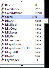
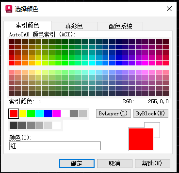
Color{get,set}:获取颜色对象,该类为AutoCAD的颜色类:![]()
ColorIndex{get,set}:获取/设置颜色索引值,需参考CAD的颜色索引,如1:红色
EntityColor entityColor = line1.EntityColor;//获取颜色对象
Color color = line1.Color;//获取颜色
int colorIndex = line1.ColorIndex;//获取颜色索引值Database:获取数据库,若实体不在数据库中,则返回null
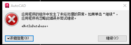
Database database = line1.Database;//获取line1的数据库,此处为nullDraw():继承自Entity,自己绘制自己,前提是必须在数据库中,否则会报下面错误,较为鸡肋,不建议用,如果图形中已经存在该实体,再调用该方法没有任何作用,了解即可。
line1.Draw();//实体自绘制,若实体不在数据库中,会报错。Delta{get}:获取方向向量,方向相同,大小相等
Normal{get,set}:获取或设置法向量,默认结果都是(0,0,1)
Vector3d vector = line1.Delta;//获取line1的方向向量
Vector3d vector2 = line1.Normal;//获取line1的法向量,结果为(0,0,1)
(2)多段线Polyline
构造:
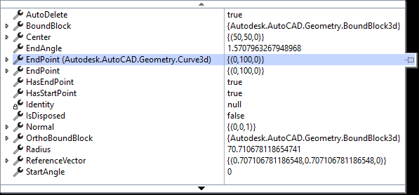
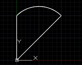
AddVertexAt(int index, Point2d pt, double bulge, double startWidth, double endWidth):添加顶点,参数分别为:顶点索引、顶点坐标、到下一个点之间的线的弯曲程度,起始线宽、终止线宽)
double bulge = Math.Tan(Math.PI / 180 * 角度差 / 4): bulge 计算公式,角度差(终点角度-起点角度,相对于弧段圆心)
bulge = 0:表示没有弯曲,即直线。bulge > 0:表示曲线的弯曲方向是向外(凸面)
bulge < 0:表示曲线的弯曲方向是向内(凹面)
Closed{get,set}:获取/设置Polyline是否闭合
 Polyline polyline = new Polyline();//初始化多段线,不限制顶点个数
 Polyline polyline2= new Polyline(4);//初始化多段线,含有四个顶点

 polyline.AddVertexAt(0, new Point2d(0, 0), 0, 0, 0);//添加顶点
 polyline.AddVertexAt(1, new Point2d(1, 0), 0, 0, 0);
 double bulge = Math.Tan(Math.PI / 180 * (90) / 4); // bulge 计算公式,这里为正,凸面
 polyline.AddVertexAt(2, new Point2d(1, 1), bulge, 0, 0);
 polyline.AddVertexAt(3, new Point2d(0, 1), 0, 0, 0);
 polyline.Closed = true;//是否闭合:是
注意:以下代码中的对象polyline均来自和上面的polyline保持一致。
方法:
Length:获取Polyline的长度
Area:获取Polyline的面积
NumberOfVertices:获取Polyline的端点个数
double Length = polyline.Length;//获取polyline的长度
double area = polyline.Area;//获取polyline的长度面积
int NumberOfVertices = polyline.NumberOfVertices;//获取polyline的端点个数,结果为4HasBulges:判断polyline是否有弧段,结果为true
IsOnlyLines:判断polyline是否都是线段Line组成的
bool HasBulge = polyline.HasBulges;//判断polyline是否有弧段,结果为true
bool IsOnlyLines = polyline.IsOnlyLines;//判断polyline是否都是线段Line组成的,结果为falseNormal{get,set}:获取/设置polyline的法向量,结果为(0,0,1)
ConstantWidth{get,set}:获取/设置polyline的线宽,结果为0
Thickness{get,set}:获取/设置polyline的厚度,结果为0
Vector3d vector = polyline.Normal;//获取polyline的法向量,结果为(0,0,1)
double ConstantWidth = polyline.ConstantWidth;//获取polyline的线宽,结果为0
double Thickness = polyline.Thickness;//获取polyline的厚度,结果为0Elevation{get,set}:获取/设置polyline的海拔高度,设置后,所有顶点的Z坐标都会设置为和海拔高度相等
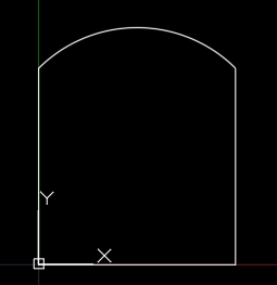
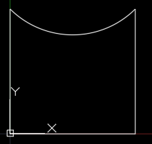
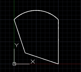
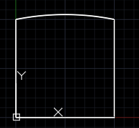
double Elevation = polyline.Elevation;//获取polyline的海拔高度,结果为0Plinegen{get,set}:判断/设置polyline是否允许在断点处分段(有虚线等特殊线存在时)
Plinegen=false时
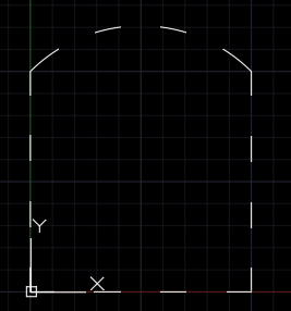
Plinegen=true时
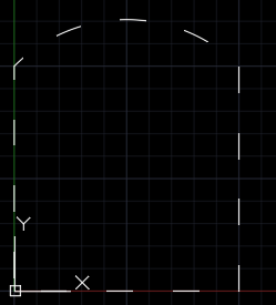
注意:这里为了虚线图像更明显,临时将尺寸修改为polyline原数据的100倍,后面的还是原来的数据
bool Plinegen = polyline.Plinegen; //判断polyline是否允许在断点处分段(有虚线等特殊线存在时),结果为false;ConvertTo(bool transferId):将polyline转换为二维多段线,参数:是否转换id号,建议用false,这样不会对原来的polyline有影响。
Polyline2d polyline2d = polyline.ConvertTo(false);GetPoint3dAt(int index):获取第index个点的三维点坐标
GetPoint2dAt(int index):获取第index个点的二维点坐标
Point3d point = polyline.GetPoint3dAt(0);//获取第0个点的三维点坐标
Point2d point2d = polyline.GetPoint2dAt(0);//获取第0个点的二维点坐标
GetSegmentType(int index):获取第index段线的线型

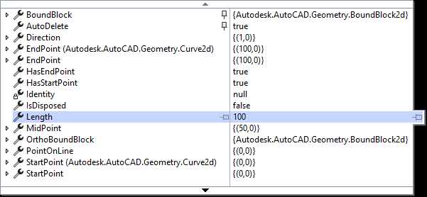
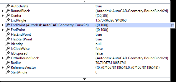
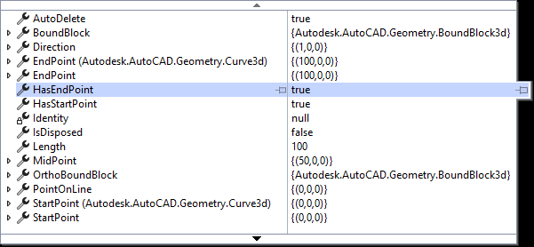
SegmentType segmentType = polyline.GetSegmentType(2);//获取第2段线的线型获取某一段的信息,包括开始点、中间点、结束点、半径、圆心等等,共有如下四种:
GetLineSegment2dAt(int index):获取第index段线的2维Line信息,即无论第index段线是什么类型,都会获取到其对应的2维Line的信息
GetArcSegment2dAt(int index):获取第index段线的2维Arc信息,即无论第index段线是什么类型,都会获取到其对应的2维Arc的信息
GetLineSegmentAt(int index):获取第index段线的3维Line信息,即无论第index段线是什么类型,都会获取到其对应的3维Line的信息
GetArcSegmentAt(int index):获取第index段线的3维Arc信息,即无论第index段线是什么类型,都会获取到其对应的3维Arc的信息
注意:不建议用获取直线信息的方法获取弧段的信息,也不建议用获取弧段信息的方法获取直线段的信息,这会导致信息和实际图像不符合。
LineSegment2d GetLineSegment2dAt= polyline.GetLineSegment2dAt(0);//获取第0段线的2维Line信息,即无论第二段线是什么类型,都会获取到其对应的2维Line的信息
CircularArc2d GetArcSegment2dAt = polyline.GetArcSegment2dAt(2);//获取第2段线的2维Arc信息,即无论第二段线是什么类型,都会获取到其对应的2维Arc的信息
LineSegment3d GetLineSegment3dAt = polyline.GetLineSegmentAt(0);//获取第0段线的3维Line信息,即无论第二段线是什么类型,都会获取到其对应的3维Line的信息
CircularArc3d GetArcSegment3dAt = polyline.GetArcSegmentAt(2);//获取第2段线的3维Arc信息,即无论第二段线是什么类型,都会获取到其对应的3维Arc的信息
OnSegmentAt(int index, Point2d pt2d, double value):判断点pt2d是否在第index段上,参数value经测试发现不起作用
bool OnSegmentAt = polyline.OnSegmentAt(2, new Point2d(50, 100),0);//判断点(50,100)是否在第2段上,结果为falseRemoveVertexAt(int index):移除第index个点(0是首个点,这里的index代表的是第 index+1个点)
polyline.RemoveVertexAt(1);//移除第1个点(0是首个点,这里的1代表的是第二个点)SetPointAt(int index, Point2d pt):将第index点的坐标重新设置为pt
polyline.SetPointAt(0, new Point2d(25, 25));//设置第0个点的坐标为(25,25)GetBulgeAt(int index):获取第index段的弯曲程度值(前面有介绍)
double GetBulgeAt = polyline.GetBulgeAt(2);//获取第2段线的弯曲值,这里约为0.414,和之前设置的一样SetBulgeAt(int index, double bulge):设置第index段的弯曲值为bulge
polyline.SetBulgeAt(2, 0.1);//设置第2段线的弯曲值为0.6GetStartWidthAt(int index):获取第index段线的开始线宽
GetEndWidthAt(int index):获取第index段线的结束线宽
SetStartWidthAt(int index, double startWidth):设置第index段线的开始线宽为startWidth
SetEndWidthAt(int index, double endWidth):设置第index段线的结束线宽为endWidth
double startWidth = polyline.GetStartWidthAt(0);//获取第0段线的开始线宽,结果为0
double endWidth = polyline.GetEndWidthAt(0);//获取第0段线的结束线宽,结果为0
polyline.SetStartWidthAt(0, 5);//设置第0段线的开始线宽为5
polyline.SetEndWidthAt(0, 10);//设置第0段线的结束线宽为10MinimizeMemory():优化折线的内存使用情况
MaximizeMemory():解压缩来加快访问速度
polyline.MinimizeMemory();//优化折线的内存使用情况
polyline.MaximizeMemory();//解压缩来加快访问速度
(3)Polyline2d
在测试过程中,Polyline2d的个别方法直接调用出现了错误,以下代码旨在介绍其功能,直接运行部分代码会导致系统崩溃
构造:
Polyline2d(Poly2dType type, Point3dCollection vertices, double elevation, [MarshalAs(UnmanagedType.U1)] bool closed, double startWidth, double endWidth, DoubleCollection bulges)
type:线型(共四种)
//SimplePoly:简单多段线
//FitCurvePoly:拟合曲线
//QuadSplinePoly:四样条曲线
//CubicSplinePoly:三样条曲线
vertices:点集合
elevation:海拔(坐标Z的值)
closed:是否闭合
startWidth:开始宽度
endWidth:结束宽度
bulges:弯曲值集合
注意:vertices中点的个数要和bulges中弯曲值的个数一样,否则程序会崩溃。
Polyline2d polyline2d = new Polyline2d();//无参构造
polyline2d = new Polyline2d(poly2dType, vertices, 0, true, 0, 0, bulges);//有参构造
Poly2dType poly2dType = Poly2dType.SimplePoly;
//SimplePoly:简单多段线
//FitCurvePoly:拟合曲线
//QuadSplinePoly:四样条曲线
//CubicSplinePoly:三样条曲线
Point3dCollection vertices = new Point3dCollection();
vertices.Add(new Point3d(0, 0, 0));
vertices.Add(new Point3d(0, 1, 0));
vertices.Add(new Point3d(1, 1, 0));
vertices.Add(new Point3d(1, 0, 0));
DoubleCollection bulges = new DoubleCollection();
bulges.Add(0);
bulges.Add(0);
bulges.Add(0);
bulges.Add(0);
Polyline2d polyline2d = new Polyline2d();//无参构造
polyline2d = new Polyline2d(poly2dType, vertices, 0, true, 0, 0, bulges);//有参构造方法:
Length:获取polyline2d长度
ConstantWidth{get,set}:获取/设置polyline2d的线宽,需要在数据库中有数据
Elevation{get,set}:获取/设置polyline2d的海拔高度
Normal{get,set}:获取/设置polyline2d的法向量
Thickness{get,set}:获取/设置polyline2d的厚度
DefaultStartWidth{get,set}:获取/设置polyline2d的默认开始宽度
DefaultEndWidth{get,set}:获取/设置polyline2d的默认结束宽度
Closed{get,set}:获取/设置polyline2d是否闭合
double Length = polyline2d.Length;//获取polyline2d长度
double ConstantWidth = polyline2d.ConstantWidth;//获取polyline2d的线宽
double Elevation = polyline2d.Elevation;//获取polyline2d的海拔高度
Vector3d Normal = polyline2d.Normal;//获取polyline2d的法向量
double Thickness = polyline2d.Thickness; //获取polyline2d的厚度
double DefaultStartWidth = polyline2d.DefaultStartWidth; //获取polyline2d的默认开始宽度
double DefaultEndWidth = polyline2d.DefaultEndWidth;//获取polyline2d的默认结束宽度

bool Closed = polyline2d.Closed;//判断polyline2d是否闭合PolyType{get,set}:获取/设置polyline2d的多段线类型(4种)
ConvertToPolyType(Poly2dType type):将polyline2d的线型设置成:type
Straighten():将polyline2d的线型设置成:SimplePoly:简单多段线,如CAD命令:Pedit-非曲线化(D)
SplineFit():将polyline2d的线型设置成:CubicSplinePoly:三次样条曲线,如CAD命令:Pedit-样条曲线(S)
SplineFit(Poly2dType value, int segments):将polyline2d的第segments段线的线型设置成:value
CurveFit():将polyline2d的线型设置成:FitCurvePoly:拟合曲线,如CAD命令:Pedit-拟合(F)
LinetypeGenerationOn:是否打开线型生成。如CAD命令:Pedit-线型生成(L),启用线型生成后,多段线使用的线型将连续生成,而不是在每个顶点处重新生成。有点类似于Polyline.Plinegen
Poly2dType PolyType = polyline2d.PolyType;//获取polyline2d的多段线类型(4种)
polyline2d.ConvertToPolyType(Poly2dType.FitCurvePoly);//将polyline2d的线型设置成:FitCurvePoly:拟合曲线
polyline2d.Straighten();//将polyline2d的线型设置成:SimplePoly:简单多段线,如CAD命令:Pedit-非曲线化(D)
polyline2d.SplineFit();//将polyline2d的线型设置成:CubicSplinePoly:三次样条曲线,如CAD命令:Pedit-样条曲线(S)
polyline2d.SplineFit(Poly2dType.QuadSplinePoly, 0);//将polyline2d的第0段线的线型设置成:QuadSplinePoly:四样条曲线

polyline2d.CurveFit();//将polyline2d的线型设置成:FitCurvePoly:拟合曲线,如CAD命令:Pedit-拟合(F)
bool LinetypeGenerationOn = polyline2d.LinetypeGenerationOn;//是否打开线型生成。如CAD命令:Pedit-线型生成(L)
Vertex2d(Point3d position, double bulge, double startWidth, double endWidth, double tangent):
tangent:正切值
NonDBAppendVertex(Vertex2d vertex):不在数据库的polyline2d添加顶点vertex
polyline2d.AppendVertex(Vertex2d vertex):在数据库的polyline2d添加顶点vertex,如果不在数据库中会报错
InsertVertexAt(ObjectId vertexId, Vertex2d newVertex):方法1:将id为vertexId的Vertex2d替换为newVertex,和方法2同效,需要在数据库中有数据
polyline2d.InsertVertexAt(Vertex2d indexVertex, Vertex2d newVertex):方法2:将顶点indexVertex替换为newVertex
Vertex2d vertex = new Vertex2d(new Point3d(-1, 1, 0), 0, 0, 0, 0);
polyline2d.NonDBAppendVertex(vertex);//不在数据库的polyline2d添加顶点vertex
polyline2d.AppendVertex(vertex);//在数据库的polyline2d添加顶点vertex
Vertex2d vertex2 = new Vertex2d(new Point3d(-2, 1, 0), 0, 0, 0, 50);
polyline2d.InsertVertexAt(vertex.ObjectId, vertex2);//方法1:将顶点vertex替换为vertex2
polyline2d.InsertVertexAt(vertex, vertex2);//方法2:将顶点vertex替换为vertex2
Point3d VertexPosition(Vertex2d vertex):获取polyline2d的顶点vertex的3d坐标Point3d
Point3d VertexPosition = polyline2d.VertexPosition(vertex);//获取polyline2d的顶点vertex的坐标(4)Polyline3d
在测试过程中,Polyline3d较多的方法直接调用时都出现了错误,以下代码旨在介绍其功能,直接运行部分代码会导致系统崩溃
构造:
Polyline3d polyline3d = new Polyline3d();//无参初始化
Polyline3d polyline3d = new Polyline3d(Poly3dType type, Point3dCollection vertices, bool closed):初始化,参数为:线型、点集合、是否闭合
 Poly3dType type = Poly3dType.SimplePoly;//设置线型
 //SimplePoly:简单多段线
 //QuadSplinePoly:四次样条曲线
 //CubicSplinePoly:三次样条曲线

 Point3dCollection points = new Point3dCollection();//设置点集合
 points.Add(new Point3d(0, 0, 0));
 points.Add(new Point3d(1, 0, 0));
 points.Add(new Point3d(1, 1, 0));
 points.Add(new Point3d(0, 1, 0));

 bool closed = true;//设置闭合

 Polyline3d polyline3d = new Polyline3d();//无参初始化
 polyline3d = new Polyline3d(type, points, closed);//初始化,参数为:线型、点集合、是否闭合(这里为true)
方法:
Length:获取polyline3d的长度属性
PolyType:获取polyline3d的线型
Closed:检查polyline3d的是否闭合
ConvertToPolyType(Poly3dType type):将polyline3d的线型设置成指定线型type
Straighten():将polyline3d的线型设置成:SimplePoly:简单多段线,如CAD命令:Pedit-非曲线化(D)
SplineFit(Poly3dType value, int segments):将polyline3d的第segments段线的线型设置成:value
SplineFit():将polyline3d的线型设置成:CubicSplinePoly:三次样条曲线,如CAD命令:Pedit-样条曲线(S)
AppendVertex(PolylineVertex3d vertexToAppend):为polyline3d添加顶点
InsertVertexAt(vertexToAppend.ObjectId, newVertex):方法1:将polyline3d的顶点vertexToAppend替换为newVertex,和方法2同效果
InsertVertexAt(vertexToAppend, newVertex):方法2:将polyline3d的顶点vertexToAppend替换为newVertex
double Length = polyline3d.Length;

Poly3dType PolyType = polyline3d.PolyType;
bool Closed = polyline3d.Closed;

polyline3d.ConvertToPolyType(Poly3dType.QuadSplinePoly);将polyline3d的线型转化为:QuadSplinePoly:四次样条曲线
polyline3d.Straighten();//将polyline3d的线型设置成:SimplePoly:简单多段线,如CAD命令:Pedit-非曲线化(D)
polyline3d.SplineFit(Poly3dType.CubicSplinePoly, 0);//将polyline3d的第0段线的线型设置成:CubicSplinePoly:三次样条曲线
polyline3d.SplineFit();//将polyline3d的线型设置成:CubicSplinePoly:三次样条曲线,如CAD命令:Pedit-样条曲线(S)


PolylineVertex3d vertexToAppend = new PolylineVertex3d(new Point3d(-1, -1, 0));//设置三维顶点
                                                                               polyline3d.AppendVertex(vertexToAppend);//为polyline3d添加顶点

PolylineVertex3d newVertex = new PolylineVertex3d(new Point3d(-1, 1, 0));
polyline3d.InsertVertexAt(vertexToAppend.ObjectId, newVertex);//方法1:将polyline3d的顶点vertexToAppend替换为newVertex,和方法2同效果
polyline3d.InsertVertexAt(vertexToAppend, newVertex);//方法2:将polyline3d的顶点vertexToAppend替换为newVertex
(5)圆 Circle
构造:
Circle circle = new Circle();//无参构造
Circle circle= new Circle(Point3d center, Vector3d normal, double radius):定义圆,参数分别为圆心、法向量、半径
Circle circle = new Circle();//无参构造
Circle circle= new Circle(new Point3d(0,0,0),new Vector3d(0,0,1),10);//定义圆:中心(0,0,0),法向量(0,0,1),半径10
方法:
circle.Diameter;//获取或设置直径
circle.Circumference;//获取或设置周长
circle.Normal;//获取或设置法向量
circle.Thickness;//获取或设置厚度
circle.Radius;//获取或设置半径
circle.Center;//获取或设置中心点
double Diameter = circle.Diameter;//获取直径
double Circumference = circle.Circumference;//获取周长
Vector3d Normal=circle.Normal;//获取法向量
double Thickness=circle.Thickness;//获取厚度
double Radius=circle.Radius;//获取半径
Point3d Center=circle.Center;//获取中心点
(6)圆弧 Arc
构造:
Arc arc = new Arc();//无参构造
Arc arc = new Arc(Point3d center, Vector3d normal, double radius, double startAngle, double endAngle);//有参构造,参数分别为圆心、法向量、半径、开始角度、结束角度
Arc arc = new Arc(Point3d center, double radius, double startAngle, double endAngle);//有参构造,参数分别为圆心、半径、开始角度、结束角度
 Arc arc = new Arc();
 arc = new Arc(new Point3d(0, 0, 0), 10, 1, 2);//定义圆心(0,0,0),半径10,起始1度(弧度),终止2度(弧度)的圆弧
 arc = new Arc(new Point3d(0, 0, 0), new Vector3d(0, 0, 1), 10, 1, 2);//定义圆心(0,0,0),法向量(0,0,1),半径10,起始1度(弧度),终止2度(弧度)的圆弧
方法:
arc.TotalAngle;//获取圆弧总角度
arc.Length;//获取圆弧长度
arc.Normal;//获取或设置法向量
arc.Thickness;//获取或设置厚度
arc.StartAngle;//获取或设置开始角度
arc.EndAngle;//获取或设置结束角度
arc.Radius;//获取或设置半径
arc.Center;//获取或设置圆心
 double TotalAngle=arc.TotalAngle;//获取圆弧总角度
 double Length=arc.Length;//获取圆弧长度

 Vector3d Normal=arc.Normal;//获取法向量
 double Thickness=arc.Thickness;//获取厚度
 double StartAngle=arc.StartAngle;//获取开始角度
 double EndAngle=arc.EndAngle;//获取结束角度
 double Radius=arc.Radius;//获取半径
 Point3d Center=arc.Center;//获取圆心
(7)多线Mline
构造:
Mline mline=new Mline();
Mline mline=new Mline();mline.NumberOfVertices;//获取mline的顶点个数
mline.SupressEndCaps;//获取或设置mline是否启用结束端的端点盖帽
mline.SupressStartCaps;//获取或设置mline是否启用开始端的端点盖帽
mline.IsClosed;//获取或设置mline是否闭合
mline.Normal;//获取或设置mline的法向量
mline.Scale;//获取或设置mline的尺寸
mline.Justification;//获取或设置mline的对齐方式
//MlineJustification.Top;//顶部对齐
//MlineJustification.Zero;//不对齐
//MlineJustification.button;//底部对齐
int NumberOfVertices=mline.NumberOfVertices;//获取mline的顶点个数

bool SupressEndCaps=mline.SupressEndCaps;//获取或设置mline是否启用结束端的端点盖帽
bool SupressStartCaps=mline.SupressStartCaps;//获取或设置mline是否启用开始端的端点盖帽

bool IsClosed=mline.IsClosed;//获取或设置mline是否闭合
Vector3d Normal=mline.Normal;//获取或设置mline的法向量
double Scale=mline.Scale;//获取或设置mline的尺寸

MlineJustification Justification=mline.Justification;//获取或设置mline的对齐方式
//MlineJustification.Top;//顶部对齐
//MlineJustification.Zero;//不对齐
//MlineJustification.button;//底部对齐


 3790
3790

 被折叠的 条评论
为什么被折叠?
被折叠的 条评论
为什么被折叠?
 到【灌水乐园】发言


