


How to wire the MGR solid state relay?
INTRODUCTION:
Solid state relays (SSR) are electronic switches that use transistors as switching components, with many advantages over traditional electromagnetic relays (EMR). For more information, please visit: SSR vs EMR .
There are many types of solid state relays, so they can be classified in many ways: For example, according to installation method, solid state relays can be divided into Panel Mount type and PCB Mount type; according to the load capacity, solid state relays can be divided into Standard Package type (rectangular shape); and Industrial Package type (long strip shape); according to the I/O (input-output) form, solid state relays can be divided into DC-DC type, AC-DC type, DC-AC type, AC-AC type; according to load voltage, solid state relays can be divided into DC type, Single Phase type and Three Phase type; and more.
Through this article you will learn how to wire the MGR/mager solid state relay.
You can quickly navigate to the chapters you are interested in through the Directory below, and the Quick Navigator on the right side of the browser.
CONTENTS
|
§1. How to Wire DC Solid State Relay |
|
§2. How to Wire AC Solid State Relay |
|
§3. How to wire Industrial AC Solid State Relay |
|
§4. How to Wire PCB Solid State Relay |
MGR solid state relays are commonly divided into DC solid state relays (DC to DC, AC to AC), AC solid state relays (AC to AC), industrial grade solid state relays (DC to DC, AC to AC), PCB mounting solid state relays (DC to DC, AC to AC), Their circuit wiring diagrams are shown as the drawing below.
§1. How to Wire DC Solid State Relay
DC Solid State Relay Wiring Diagram
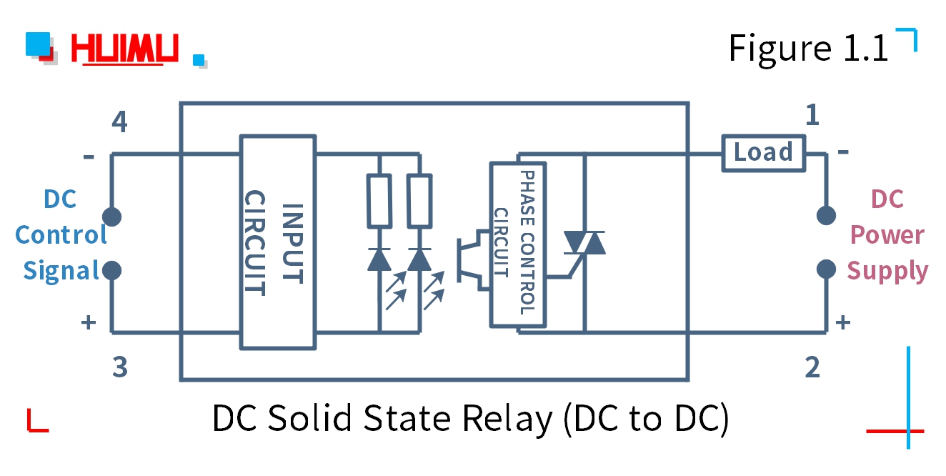
1.1 DC to DC Solid State Relay
MGR-1DD series
The DC to DC solid state relay is a four-terminal electronic device that uses a DC signal to control the DC load. The 1 and 2 ports of DC-DC solid state switch are connected to the load and the DC power supply, 3 and 4 ports are connected to the DC control device.
Note: Before installation and use, please confirm whether the specifications (such as input current, input voltage, output current, output voltage and etc.) of the solid state relay meet the requirements of the application.
MGR-5DD series
The circuit wiring diagram of the MINI DC to DC Solid State Relay is the same as the zero-crossing dc to dc solid state relay.
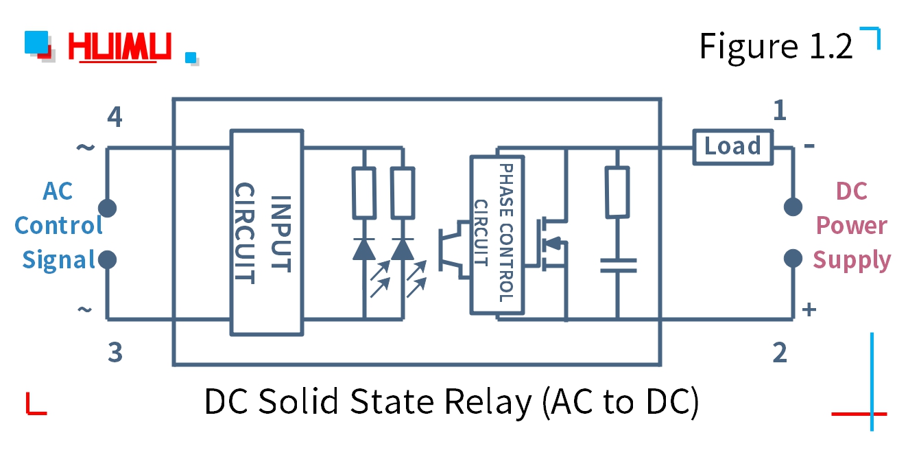
1.2 AC to DC Solid State Relay
MGR-1AD series
The AC to DC solid state relay is a four-terminal electronic device that uses an AC signal to control the DC load. The 1 and 2 ports of AC-DC solid state switch are connected to the load and the DC power supply. 3 and 4 ports are connected to the AC control device.
Note: Before installation and use, please confirm whether the specifications (such as input current, input voltage, output current, output voltage and etc.) of the solid state relay meet the requirements of the application.
§2. How to Wire AC Solid State Relay
AC Solid State Relay Wiring Diagram
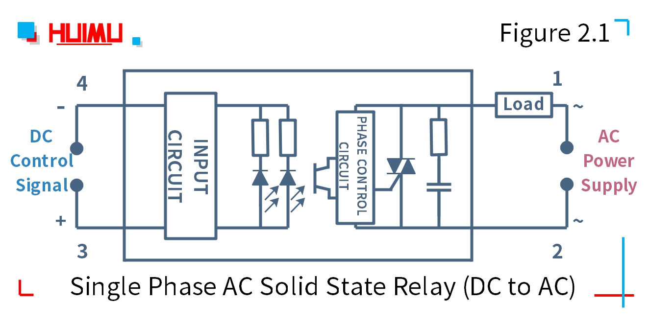
2.1 Single Phase DC to AC Solid State Relay
MGR-1D series
The single phase DC to AC solid state relay is a four-terminal electronic device that uses a DC signal to control the single phase AC load. The 1 and 2 ports of DC-AC solid state switch are connected to the load and the single phase AC power supply, 3 and 4 ports are connected to the DC control device.
Note: Before installation and use, please confirm whether the specifications (such as input current, input voltage, output current, output voltage and etc.) of the solid state relay meet the requirements of the application.
MGR-1D48-40P series
The circuit wiring diagram of the Random Conduction DC to AC Solid State Relay (or random fire dc to ac ssr) is the same as the zero-crossing dc to ac solid state relay.
MGR-1X4810 series
The circuit wiring diagram of the MINI DC to AC Solid State Relay is the same as the zero-crossing dc to ac solid state relay.
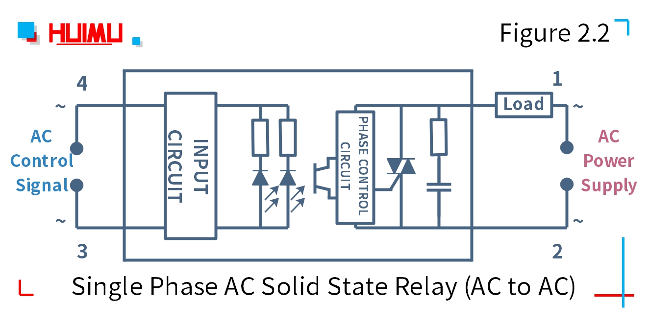
2.2 Single Phase AC to AC Solid State Relay
MGR-1A series
The single phase AC to AC solid state relay is a four-terminal electronic device that uses a single phase AC signal to control the single phase AC load. The 1 and 2 ports of AC-AC solid state switch are connected to the load and the single phase AC power supply, 3 and 4 ports are connected to the single phase AC control device.
Note: Before installation and use, please confirm whether the specifications (such as input current, input voltage, output current, output voltage and etc.) of the solid state relay meet the requirements of the application.
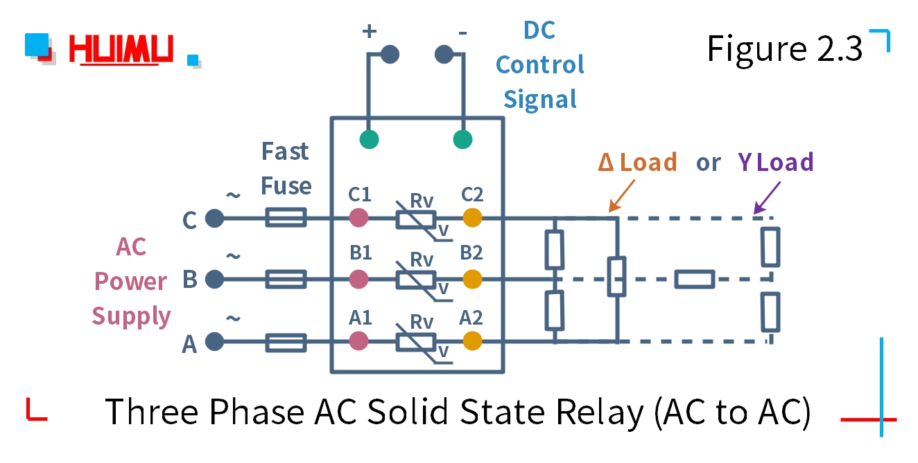
2.3 Three Phase DC to AC Solid State Relay
MGR-3-032 series
The three phase DC to AC solid state relay is an eight-terminal electronic device that uses a DC signal to control three phase AC load. A1, B1, C1 ports of three phase DC-AC solid state switch are connected to the three phase AC power supply; A2, B2, C2 ports are connected to the Δ load (delta load) or Y load. "+" and "-" ports are connected to DC control device.
Note: Before installation and use, please confirm whether the specifications (such as input current, input voltage, output current, output voltage and etc. ) of the solid state relay meet the requirements of the application.
MGR-3X-48D25Z series
The circuit wiring diagram of the Compact Three Phase AC to AC Solid State Relay is the same as the zero-crossing three phase ac to ac solid state relay.
2.4 Three Phase AC to AC Solid State Relay
MGR-3-A series
The three phase AC to AC solid state relay is an eight-terminal electronic device that uses a single phase AC signal to control three phase AC load. A1, B1, C1 ports of three phase AC-AC solid state switch are connected to the three phase AC power supply; A2, B2, C2 ports are connected to the Δ load (delta load) or Y load. The input circuit of the three phase ac to ac SSR are connected to single phase AC control device.
Note: Before installation and use, please confirm whether the specifications (such as input current, input voltage, output current, output voltage and etc.) of the solid state relay meet the requirements of the application.
MGR-3X-48A25ZZ series
The circuit wiring diagram of the Compact Three Phase AC to AC Solid State Relay is the same as the zero-crossing three phase ac to ac solid state relay.

§3. How to wire Industrial AC Solid State Relay
Industrial AC Solid State Relay Wiring Diagram
3.1 Industrial Single Phase DC to AC Solid State Relay
MGR-H series
The standard type industrial DC to AC solid state relay is a four-terminal electronic device that uses a DC signal to control the single phase AC load. The input circuit of the industrial DC-AC solid state switch is connected to the DC control device. And LED indicators shows the working status. The output circuit is connected to a single phase AC load. The industrial single phase dc to ac SSR is installed in the application device by the standard mounting flange.
MGR-H3100P , MGR-H3200P series
The circuit wiring diagram of the industrial random conduction DC to AC solid state relay (or industrial random fire dc to ac ssr) is the same as the zero-crossing dc to ac solid state relay.
Note: Before installation and use, please confirm whether the specifications (such as input current, input voltage, output current, output voltage and etc.) of the solid state relay meet the requirements of the application.

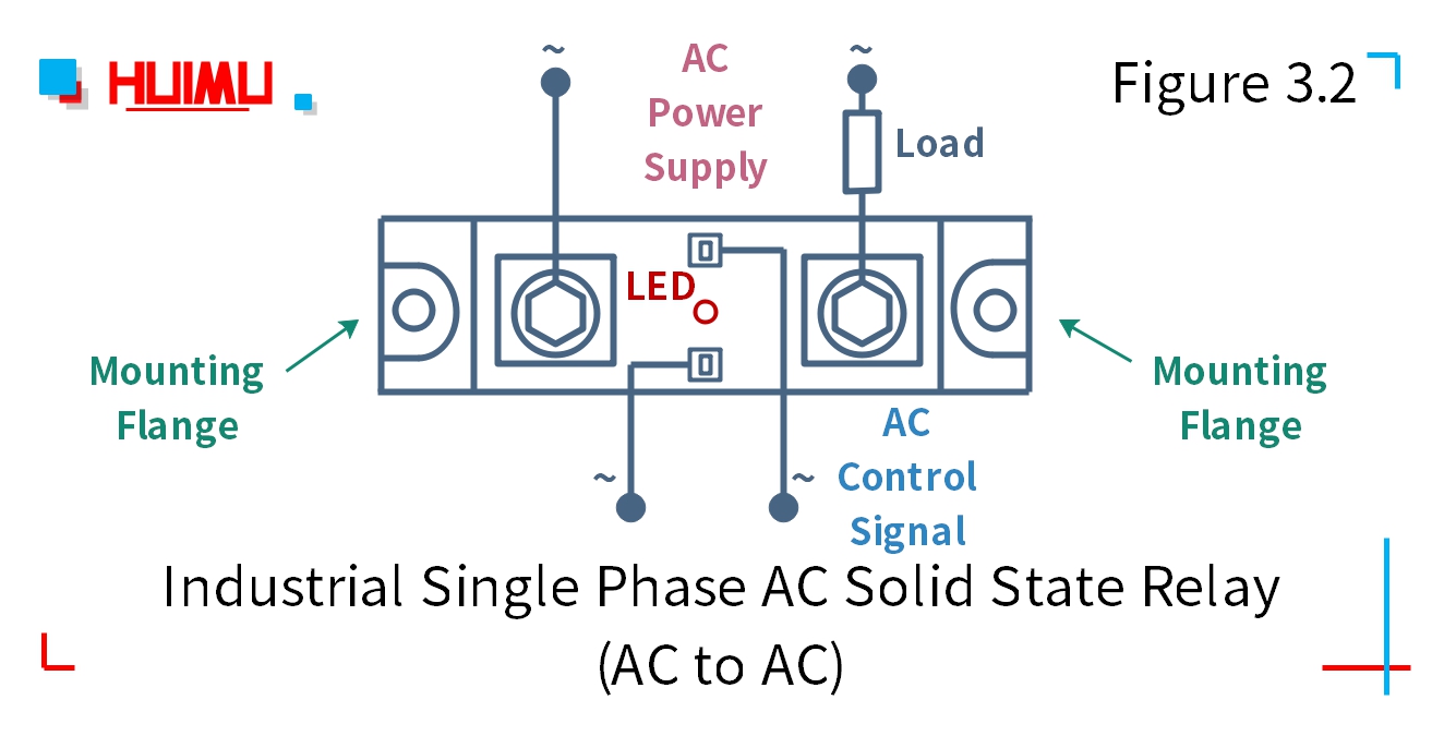
3.2 Industrial Single Phase AC to AC Solid State Relay
MGR-AH series.
The standard type industrial AC to AC solid state relay is a four-terminal electronic device that uses a single phase AC signal to control the single phase AC load. The input circuit of the industrial AC-AC solid state switch is connected to the single phase AC control device. And LED indicators shows the working status. The output circuit is connected to a single phase AC load. The industrial single phase ac to ac SSR is installed in the application device by the standard mounting flange.
Note: Before installation and use, please confirm whether the specifications (such as input current, input voltage, output current, output voltage and etc.) of the solid state relay meet the requirements of the application.
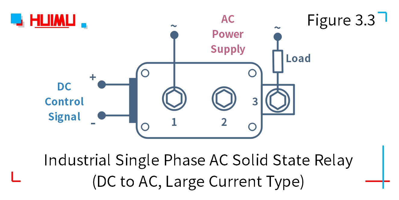
3.3 Industrial Single Phase DC to AC Solid State Relay (High Current Type)
MGR-H series
The large current type industrial DC to AC solid state relay uses a DC signal to control the single phase AC load. The input circuit is connected to the DC control device. The output circuit is connected to the single phase AC load through 1 and 3 ports.
Note: Before installation and use, please confirm whether the specifications (such as input current, input voltage, output current, output voltage and etc.) of the solid state relay meet the requirements of the application.
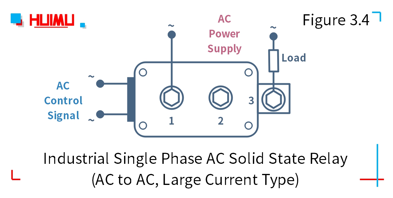
3.4 Industrial Single Phase AC to AC Solid State Relay (High Current Type)
MGR-AH series
The large current type industrial AC to AC solid state relay uses a single phase AC signal to control the single phase AC load. The input circuit is connected to the single phase AC control device. The output circuit is connected to the single phase AC load through 1 and 3 ports.
Note: Before installation and use, please confirm whether the specifications (such as input current, input voltage, output current, output voltage and etc.) of the solid state relay meet the requirements of the application.
3.5 Industrial Three Phase DC to AC Combined Solid State Relay
MGR-H_3 series.
The combined type three phase industrial DC to AC solid state relay consists of three standard type DC to AC industrial solid state switches, a 220VAC fan, an 85°C temperature control switch and a heat sink. This type of three phase industrial SSR uses a DC signal to control the three phase AC load. The input circuit is connected to the DC control device. The output circuit is connected to the three phase AC power supply and load.
Note: Before installation and use, please confirm whether the specifications (such as input current, input voltage, output current, output voltage and etc.) of the solid state relay meet the requirements of the application.

3.6 Industrial Three Phase AC to AC Combined Solid State Relay
MGR-AH_3 series.
The combined type three phase industrial AC to AC solid state relay consists of three standard type AC to AC industrial solid state switches, a 220VAC fan, an 85°C temperature control switch and a heat sink. This type of three phase industrial SSR uses a single phase AC signal to control the three phase AC load. The input circuit is connected to the single phase AC control device. The output circuit is connected to the three phase AC power supply and load.
Note: Before installation and use, please confirm whether the specifications (such as input current, input voltage, output current, output voltage and etc.) of the solid state relay meet the requirements of the application.

§4. How to wire PCB Solid State Relay
PCB Solid State Relay Wiring Diagram
4.1 PCB DC to DC Solid State Relay (SIP)
GJ-FA-L series
The SIP PCB mounting DC to DC solid state relay uses a DC signal to control the DC load. The input circuit of PCB mounting DC-DC solid state switch is connected to the DC control device. The output circuit is connected to the DC power supply and the load. The solid state relay uses the SIP 4-pin package and standard British PCB mounting dimensions.
Note: Before installation and use, please confirm whether the specifications (such as input current, input voltage, output current, output voltage and etc.) of the solid state relay meet the requirements of the application.

4.2 PCB DC to DC Solid State Relay (DIP)
JGX-FA series
The DIP PCB mounting DC to DC solid state relay uses a DC signal to control the DC load. The input circuit of PCB mounting DC-DC solid state switch is connected to the DC control device. The output circuit is connected to the DC power supply and the load. The solid state relay uses the DIP 4-pin package and standard British PCB mounting dimensions.
Note: Before installation and use, please confirm whether the specifications (such as input current, input voltage, output current, output voltage and etc.) of the solid state relay meet the requirements of the application.
JGX-F-S series
The circuit wiring diagram of the Heat Sink Type DIP PCB Mounting DC to DC Solid State Relay is the same as the DIP dc to dc solid state relay.

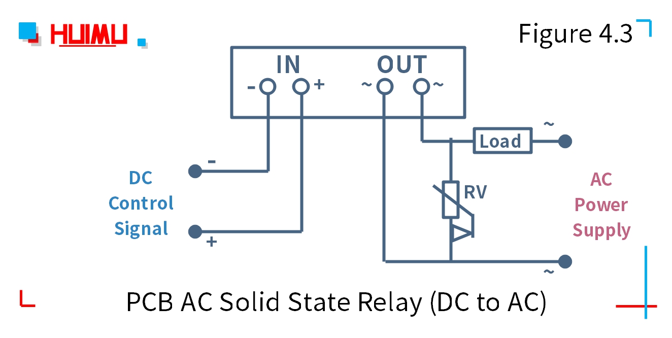
4.3 PCB DC to AC Solid State Relay (SIP)
GJ-L series
The SIP PCB mounting DC to AC solid state relay uses a DC signal to control the single phase AC load. The input circuit of PCB mounting DC-AC solid state switch is connected to the DC control device. The output circuit is connected to the single phase AC power supply and the load. The solid state relay uses the SIP 4-pin package and standard British PCB mounting dimensions.
Note: Before installation and use, please confirm whether the specifications (such as input current, input voltage, output current, output voltage and etc.) of the solid state relay meet the requirements of the application.
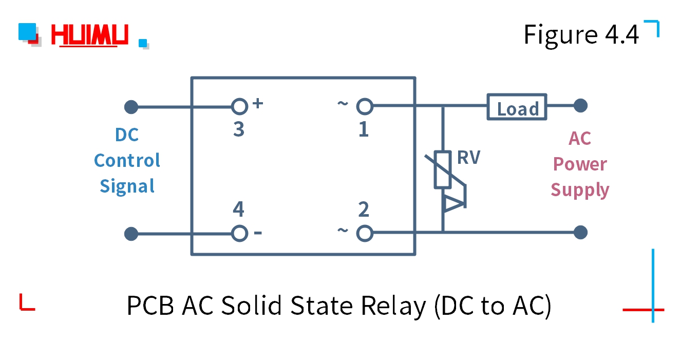
4.4 PCB DC to AC Solid State Relay (DIP)
The DIP PCB mounting DC to AC solid state relay uses a DC signal to control the single phase AC load. The input circuit of PCB mounting DC-AC solid state switch is connected to the DC control device. The output circuit is connected to the single phase AC power supply and the load. The solid state relay uses the DIP 4-pin package and standard British PCB mounting dimensions.
Note: Before installation and use, please confirm whether the specifications (such as input current, input voltage, output current, output voltage and etc.) of the solid state relay meet the requirements of the application.
JGX-F-S series
The circuit wiring diagram of the Heat Sink Type DIP PCB Mounting DC to AC Solid State Relay is the same as the DIP dc to ac solid state relay.


 680
680


 被折叠的 条评论
为什么被折叠?
被折叠的 条评论
为什么被折叠?
 到【灌水乐园】发言


