USB枚举和HID枚举实例

在说枚举过程之前,先把一些必须了解的说明白

一.USB包结构和分类

     包的共同特点是,都是以同步域开始,接着是PID,最后以EOP结束,而设备端则靠SEI(串行接口引擎,硬件上实现)来进行这些底层的处理,包括CRC的校验之类的东东。

    8位的PID,PID0~PID3,用于表示包,高四位进行取反,进行校验

    各种包的如下:

    令牌类:OUT,IN ,SOF,SETUP

    数据类:DATA0,DATA1,DATA2,MDATA

    握手类:ACK,NCK,STALL,NYET

    特殊类:PRE,ERR,SPLIT,PING

    令牌包用于启动一次USB传输,这些IN,OUT都以主设备而言的

    SETUP建立控制传输过程

    令牌包的结构为,

    同步域+PID+7位地址+4位端点号+5位CRC校验+EOP

    数据包的结构为,

    同步域+PID+字节0~字节N+CRC+EOP

    在数据包中,我们看到有DATA0和DATA1,这实际上形成了一种数据纠错机制。

    在数据发送成功或者接收时,数据包类型切换,如果检测到包类型没有切换,说明刚刚的数据传输没有发送成功。否则表示成功接收到数据了,虽然也有握手包来说明问题。

   握手包

   同步域+包标识+EOP


二.事务

   不能简单的通过包来进行数据传输,所以由不同的包组织而成事务,就是所谓的transcation

一个事务通常由三个不同类型的包组成,令牌包,数据包,握手包

令牌包启动事务,握手包返回信息,数据包传输数据,方向由令牌包决定

我们知道USB中有4中传输类型,批量传输,等时传输,中断传输和控制传输,控制传输一般用于总线的枚举过程。

控制传输事务有三个过程,包括建立过程,数据过程,状态过程

其余三种传输对应一个事务

我们挑控制传输说明问题,其余就简单了

   这里有个有趣的东西,setup只能使用DATA0,在数据传输过程中,一旦数据传输方向发生变化,就会认为进入了状态过程,数据传输的第一个过程必须是DATA1包,每次传输正确之后是在DATA0和DATA1中切换,而状态事务只能使用DATA1包。

USB设备的检测机制,在前面已经说过了,说个有意思的二次枚举的应用(因为重新上电之后就会有BUS的枚举设备过程)当设备插入之后,它先被识别成一个设备,该设备负责从主机上下载固件到设备的RAM内,然后设备将上拉电阻断开(模拟拔下,设备未断电,可以对口线进行操作就可以了),接着重新连接上拉电阻,当重新检测到设备时,使用的是已经下载的固件了,这就是不用烧录器的好处,只要改固件程序。


三.USB设备枚举过程

下面是USB设备枚举的过程

1. 主机发起第一个控制传输(获取设备描述):

(1)主机SETUP包(发往地址0端点0)、主机数据包(请求设备描述符)、设备握手包ACK。

设备产生端点0数据输出中断,固件程序要根据数据包中的主机要求做好准备,这里是在端点0输入缓冲区准备好设备描述符。

(2)数据过程,主机先发一个IN令牌包、设备发一个数据包(这个数据已经准备好,SIE收到IN令牌后,直接送到总线上,用户此时不干预)、主机发ACK包。

此时SIE产生端点0数据输入中断,表明主机已经取走了设备所准备的数据,用户也可以在该中断处理程序中作自己的处理。(如清理操作等)

此时,主机只接受一次数据,最少8个字节。如果用户数据没有发完,又在控制端点输入缓冲区,准备了数据,主机也不理会。

(3)状态过程:主机发OUT包(通知设备要输出)、主机发0字节状态数据包(这个是0字节,表明自己收到设备描述符)、设备发握手ACK包。

此时设备不会产生端点0数据输出中断,此时没有数据。


2、枚举过程中,第二个来回:设置地址。

第一个来回成功以后,主机再次复位总线。进入地址设置控制传输阶段。

(1)主机SETUP包(发往地址0端点0)、主机数据包(请求设置地址)、设备握手包ACK。所以SETUP包后面都会跟一个表明主机SETUP目的的数据包,要么GET,要么SET。

设备产生端点0数据输出中断,固件程序要根据数据包中的主机要求做好准备,这里是在根据主机发来的地址写入自己的地址控制寄存器。

(2)数据过程,本次传输没有数据。

(3)状态过程:主机发IN包(通知设备要返回数据)、设备发0字节状态数据包(表明地址设置已经成功)、主机发握手ACK包(地址设置已经生效)。

此时设备不会产生端点0数据输入中断,此时没有数据。


3、枚举过程中,第三个来回:主机使用新地址获取完整的设备描述符。

主机采用新地址发起第一个控制传输:

(1)主机SETUP包(发往新的地址端点0)、主机数据包(请求设备描述符)、设备握手包ACK。

设备产生端点0数据输出中断,固件程序要根据数据包中的主机要求做好准备,这里是在端点0输入缓冲区准备好设备描述符。

(2)数据过程,主机先发一个IN令牌包、设备发一个数据包(这个数据已经准备好,SIE收到IN令牌后,直接送到总线上,用户此时不干预)、主机发ACK包。

此时SIE产生端点0数据输入中断,表明主机已经取走了设备所准备的数据,用户可以该中断处理程序中要做如下处理:如果一次没有将描述符送完,要再次将剩下的内容填充端点0输入缓冲区。

第二次数据传输:主机再发一个IN令牌包、设备发一个数据包、主机发ACK包。

此时SIE再次产生端点0数据输入中断,如果数据已经发完了。这里就不处理了。进入状态过程。

(3)状态过程:主机发OUT包(通知设备要输出)、主机发0字节状态数据包(表明自己收到设备描述符)、设备发握手ACK包。

接下来获取配置描述符、配置集合、字符串描述符、报告描述符的过程差不多,这里就不再叙述了。

具体可以看下图:


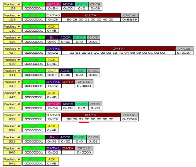
上面说的前两个过程在BUS bound中是看不到的,上图来自网络

具体的上面已经说得很清楚了

其中红线的部分就是设置的地址,


set_address请求的结构为

bmrequestType 0x00

SET_ADDRESS 0x05

wValue 设备地址(上面提到的0x0002,设备地址一般从地址0开始分配)

wIndex 0x0000

wLength 0x0000

具体可以看文档

四.USB HID设备(鼠标)的枚举过程

以上的截图是通过BUS BOUND得到的,不过没有set_address前的枚举过程而已。

(1)   取得设备描述符    get device descriptor

80 06 00 01 00 00 12 00

80         标准请求数据传输方向设备到主机

06         取得描述符请求Get Descriptor

0100     01表示的设备描述符 00描述符的索引

0000     读取描述符时字符串的语言ID号

0012     18字节需要返回取得的字节数

(2)   设备描述符

12 01 10 01 00 00 00 08 3a 09 10 25 00 01 01 02 00 01

12         18字节设备描述符长度

01         设备描述符

0110     USB设备的USB协议为1.1

00          设备使用的类代码一般这里定义为0 协议在接口描述符中定义

00         子类代码

00         设备使用的协议

08         端点0的最大包长

093a      厂商的ID

2510            产品ID              这两个值可以在设备属性中看到

0100      版本号1.0

01          描述厂商的字符串的索引值    

02          产品的字符串索引值

00          设备的序列号字符串索引值   为0表示没有序列号字符串

01          设备有多少种配置      

(3)   取得配置描述符 Get Descriptor

80 06 00 02 00 00 09 00

这里取得描述符(1)类似

02 表示取得配置描述符

00 09 希望取得的配置描述符长度

(4)   配置描述符

09 02 22 00 01 01 04 a0 32

09         length

02         configuration descriptor

0022     配置描述符总长度34字节

01         该配置所支持的接口数01 鼠标是一个接口,一个接口代表一个功能

01                配置值为01      当set config时,如果找到与配置值匹配的,则设置为此配置

04          配置字符串的索引值

a0                 a0对应的二进制位10100000 D7为1是必须的,D6为1表示为设备自供电,为0表示总线供电,D5为1表示支持远程唤醒为0表示不支持其余位为0

32                    表示需要从总线获得的最大电流量 2mA*0x32=100mA

(5)     再次取得配置描述符(具体)

80 06 00 02 00 00 22 00

这里的0x0022就是在上一个描述中得到的

(6)     具体的配置描述符

包括配置描述符,接口描述符,类描述符(如果有的话),端点描述符

09 02 22 00 01 01 04 a0 32 09 04 00 00 01 03 01 02 00 09 21 11 01 00 01 22 3e 00 07 05 81 03 04 00 0a


其中配置描述符

09 02 22 00 01 01 04 a0 32


接口描述符

09 04 00 00 01 03 01 02 00

09 接口描述符长度

04 接口描述符

00 接口的编号编号为0(如果有很多接口这里会逐个显示)

00 接口的备用编号为0

01该接口使用的端点数   只是用一个端点(中断端点)不包括0端点

03 该接口所使用的类 USB鼠标为HID类,编码03

01 该接口所使用的子类01 这个子类支持BIOS引导启动的子类

02 协议 01为键盘 02 为鼠标

00 接口所使用的字符串索引值00 为没有


类描述符(HID类)

09 21 11 01 00 01 22 3e 00

09 类描述长度

21 HID描述符

0111 使用的HID协议1.11

00  设备适用的国家

01 下级描述符的数量至少为1,报告描述符或者物理描述符

22  下级描述符的类型 0x22报告描述符 0x23物理描述符

003e 下级描述符的长度当有多个下级描述符时,上述两值交替下去


端点描述符

07  05 81 03 04 00 0a

07   端点描述符的长度

05  端点描述符类型

81  端点的地址10000001 D7表示传输方向 1为输入 D6~D4 reserved D3~D0为端点号端点号为01

03    端点的属性 D1~D0表示端点的传输类型 11表示为中断传输 10批量传输 01等时传输 00控制传输非等时传输D7~D2为0

0004 支持最大的包长度最大长度为4 对于高速设备这里有新的解释

0a    表示端点查询的时间对于中断端点表示查询的帧间隔数

(7)设置配置

00 09 01 00 00 00 00 00

00 设置

09 设置配置

0001 配置的值为1,这里与上面配置1相匹配,选中该配置

0x0000 wIndex

0x0000 wLength

(8) set IDLE请求

这个请求要求设备在没有新的事件发生时,不要从中断端点中返回数据。

HID中类请求有set_idle ,get_idle,get_report,set_report HID鼠标可以不用理会

(9)get descriptor

这里取的是接口描述符

81的后五位D4~D0表示请求的接收者

0 设备

1 接口

2 端点

3 其他

4~31 保留

81 06 00 22 00 00 7e 00

22 请求的描述符为HID的报告描述符 0x23为物理描述符

007e 请求的报告描述符长度(不懂为啥是这个,需要看主设备驱动和文档)

(10)报告描述符

HID中有短条目和长条目之分

一般使用短条目包括1字节的前缀和可选的数据字节组成

一般是加1字节可选字节为0,1,2,4字节

前缀的1字节的结构为

D7~D4 bTag      条目功能

D3~D2 bType    条目类型 0 主条目 1为全局条目 2为局部条目 3reserved

D1~D0 bSize      条目后面所跟数据的字节数

00 0字节 01 1字节 10 2字节 11 4字节

       具体的报告描述符带看HID文档,这里就不多说了。。

  • 1
    点赞
  • 6
    收藏
    觉得还不错? 一键收藏
  • 0
    评论
Bus Hound 5.0<br><br>Copyright (C) Perisoft 2000-2003. All rights reserved worldwide.<br><br>Bus Hound is a powerful software bus analyzer for capturing I/O and protocol from devices. Features include:<br><br> Supports every version of IDE, SCSI, USB, 1394<br> Supports all devices such as hard drives, DVD, mice, scanners, web cams, and everything else<br> Supports Windows 95, 98, Me, NT 4.0, 2000, 2003, XP and XP Embedded<br> Capture megabytes of I/O limited only by available memory<br> Automatically stop the capture upon a trigger condition<br> Measure individual read, write, and isochronous device performance<br> Captures device driver packets such as IRP’s<br> Filter what type of phases are captured<br> Run on an unlimited number of machines at the same time<br> Capture any number of devices in parallel, regardless of bus type<br> Fits on a diskette for easy transportability and quick downloads<br> Drag and drop captured data to other products in html format<br> Save captured data to a text file or zip file<br> Simple device selection from a graphical tree of devices<br> Capture the system startup process<br> Arrange captured data to user preferences such as the byte width per line<br> View low level protocol including SCSI sense data and USB setup packets<br> View microsecond resolution timing of each phase<br> Watch I/O on screen in real time as it happens<br> Pure software solution--no extra hardware or system changes needed<br><br><br><br>The Capture Window<br><br>Commands sent to devices consist of one or more phases. Examples of phases are command bytes, data bytes, and status bytes. Bus hound logs each phase complete with timing information and a description of the content.<br><br>Capture columns<br><br>Below are descriptions of information in each column of the Capture Window:<br><br>Device<br><br>Device ID. Each device is assigned a number which can be matched up with devices in the Devices Window. The first detected device on the system is Device ID 0, the second is Device ID 1, and so on. This field is useful in the event multiple devices are being captured in parallel.<br><br>For USB devices, the endpoint is also displayed (eg: 4.1 = device 4, endpoint 1).<br><br>Phase<br><br>Phase type. Please refer to the table for details of each phase type.<br><br>Phase Description<br>ADDR 8 byte 1394 transfer address<br>ATI 7 byte ATA task file returned from an IDE device<br>ATO 7 byte ATA task file sent to an IDE device <br>ATP Windows ATA_PASS_THROUGH data structure<br>CDB SCSI command descriptor block<br> (Known as a packet command for ATAPI devices)<br>CTL 8 byte setup packet of a USB control transfer<br>DI Data In (Device to PC transfer)<br>DO Data Out (PC to device transfer)<br>IOR Windows VXD I/O Request data structure<br>IRB Windows 1394 I/O Request Block data structure<br>IRP Windows I/O Request Packet data structure<br>ISOC Isochronous transfer data bytes<br>LEN Data transfer length of a DI,DO, or ISOC phase in <br> decimal units. This field is off by default and can be<br> turned on from the settings Window<br>LOCK 1394 lock transaction<br>NSTS Windows 4 byte kernel mode NTSTATUS field<br>RSET Bus or device reset<br>RSTS Windows VXD IOR status<br>SNS SCSI request sense data<br>SPT Windows SCSI Pass Through data structure<br>SRB Windows SCSI Request Block (SRB) data structure<br>SSTS Windows 1 byte SCSI Request Block (SRB) status<br>STAK Windows IO_STACK_LOCATION data structure<br>URB Windows USB Request Block (URB) data structure<br>USTS Windows 4 byte USBD_STATUS code<br><br><br>Data<br><br>Data bytes associated with the phase. Examples are command bytes, data transfer bytes, and status bytes.<br><br>Description<br><br>A text description of this phase provided for your convenience.<br><br>Delta<br><br>Elapsed time from the previous phase to the current phase. The following table describes the units of the time format.<br><br>Name Units<br>us Microseconds<br>ms Milliseconds<br>sc Seconds<br>mn Minutes<br>hr Hours<br>dy Days<br><br><br>Cmd.Phase.Ofs(rep)<br><br>This unique tag identifies the exact position within the captured data. All values are in decimal.<br><br>Cmd is the command number. Commands start at 1 and increment for each new command sent to a device.<br><br>Phase is the phase number within this command. A command is usually composed of multiple phases such as data transfer and status. This value starts at 1 and increments for each new phase within the command.<br><br>Ofs is the byte offset of the data within this phase. This value starts at 0 and increments for each byte of data in the data transfer.<br><br>Rep is the number of identical commands issued back to back. The repeat count feature can be turned off by deselecting the “Merge Repeated Commands” check box in the settings Window.<br><br>Date<br><br>Date the phase occurred in year/month/day format.<br><br>Time<br><br>Time the phase occurred in hour:minute:second.millisecond format. The hour ranges from 0 to 23 (military time).<br><br><br>Capturing the system startup process<br><br>If the Bus Hound application is exited while the Run button is pressed, the device driver portion of Bus Hound continues capturing data. In the event the system is restarted, it will start capturing data early in the system startup process.<br><br>If Bus Hound is exited while stopped, no capture will occur until returning to the product and pressing Run.<br><br>Customizing the capture display<br><br>The column order can be modified by dragging the column headers to the desired position. The byte width per line can be 1, 2, 4, 8, 16, or 32 bytes and is based on the width of the window. These settings are respected for Saving and drag & drop.<br><br>Searching<br><br>Searching can be performed from the capture window in either the up or down direction by typing the search string in the lower left edit box followed by pressing the up or down arrow to search up or down respectively. If the search string is not found, the trace position is not changed. Searching is not case sensitive.<br><br>Drag and Drop<br><br>To use drag and drop, first select the desired range of lines by clicking on the starting line, then hold down shift and click the ending line. The data can now be dragged using the mouse to another product.<br><br>Pressing control-c copies the selected lines to the clipboard.<br><br>Command Overlap<br><br>Overlapped commands are identified when a command starts before previous commands to the same device have completed. It is possible for Commands to be overlapped at the I/O subsystem level (which Bus Hound displays), but not at the hardware level.<br><br>Multiple DI/DO phases<br><br>Windows 9x only: if multiple DI/DO phases are listed for the same command, it indicates the transfer was split across multiple memory address ranges<br><br>PS2 Mouse data format<br><br>Below is the format of the data returned in the data in phase for PS/2 mice. This is known as the MOUSE_INPUT_DATA structure in the Windows DDK:<br><br>Offset Length Content<br>0 2 Not used<br>2 2 Position type:<br> 0000h = relative position<br> 0001h = absolute position<br>4 2 Button flags:<br> 0001h = left button down<br> 0002h = left button up<br> 0004h = right button down<br> 0008h = right button up<br> 0010h = middle button down<br> 0020h = middle button up<br> 0040h = button 4 down<br> 0080h = button 4 up<br> 0100h = button 5 down<br> 0200h = button 5 up<br> 0400h = mouse wheel<br>6 2 Mouse wheel data<br>8 4 Not used<br>12 4 X position<br>16 4 Y position<br>20 4 Device specific information<br><br>PS2 Keyboard data format<br><br>Below is the format of the data returned in the data in phase for PS/2 keyboards. This is known as the KEYBOARD_INPUT_DATA structure in the Windows DDK:<br><br>Offset Length Content<br>0 2 Not used<br>2 2 Scan code of key<br>4 2 Flags:<br> 0000h = key pressed<br> 0001h = key released<br> 0002h = extended scan code E0<br> 0004h = extended scan code E1<br>6 2 Not used<br>8 4 Device specific information<br><br><br><br>The Save Window<br><br>The Save button saves all captured data to the specified file. The format of the file can be either a text file containing standard ASCII characters or a Zip file. The data will be saved in the same column order and byte width as seen on the screen.<br><br>A comment can be provided that will be placed into the header of the captured data. The current date and time can be included in the comment by inserting %c anywhere inside the comment. If saving to a zip file, the comment is also used for the zip file comment.<br><br><br><br>The Settings Window<br><br>This Window allows you to customize the capture process. Checkbox options in this window are applied instantly. Numeric entries are applied by pressing the apply button, switching to another window, or exiting Bus Hound.<br><br>Buffer Size<br><br>Specifies the number of kilobytes of RAM to use for capturing data. The size is limited only by system RAM. If not enough RAM is available to satisfy the requested size, the size is reduced to available RAM. If you need to get as much space as possible, besides adding more RAM to a system you can also try setting the buffer size before starting other applications. Note: allocating a very large buffer size under Windows 95/98/Me can take a minute.<br><br>Max Phase<br><br>Specifies the maximum number of bytes that will be captured on each phase. Example: if Max Phase is set to 32 bytes and a 64K read operation occurs, only the first 32 bytes of the read will be captured. This option is useful for keeping the size of the captured data to a minimum.<br><br>Stop When...<br><br>These are triggers that allow the capture to automatically stop when the specified condition is met. Any combination of triggers may be selected. When a trigger condition is met, the capture stops and the trigger text is highlighted in red.<br><br>Any Other Error stops the capture when an error occurs that does not fall into any of the other categories.<br><br>Buffer Full stops the capture when Bus Hound's buffer is full. If Buffer Full is deselected, capturing continues after the buffer is full, keeping the most recently captured data.<br><br>Bus Reset stops the capture when a bus reset occurs.<br><br>Data Overrun stops the capture when a data overrun or data underrun occurs.<br><br>Hardware Error stops the capture when a hardware error occurs.<br><br>Invalid Command stops the capture when an invalid command is issued.<br><br>Media Error stops the capture when a device reports a media error such as a bad sector.<br><br>No Media stops the capture when a device reports no media is present.<br><br>Not Ready stops the capture upon a not ready, timeout, or busy condition.<br><br>Text Pattern / Hex Pattern stops the capture when the specified data pattern is detected in the captured data. For text patterns, the match is case sensitive. The pattern is checked against the data transferred in any phase including commands, data, and status.<br><br>Vendor Error stops the capture when a vendor unique error occurs.<br><br>Windows Error stops the capture when an operating system type error occurs.<br><br>Phases to Capture<br><br>Contains a list of all the phase types Bus Hound can capture. Placing a check mark next to a phase allows it to be captured. Removing a check mark next to a phase results in the phase not being captured. This option is useful for filtering out phases that are not of interest or including special operating system phases that are off by default.<br><br>To the right of the check box, a white circle may appear. This indicates the phase has been detected and exists in the captured data. If the circle blinks bright green, it is a real time activity light indicating the phase has occurred and has been captured.<br><br>Merge Repeated Commands<br><br>When selected, if a command occurs that is identical to the previous command, the new command will not be logged separately. Instead, the repeat count of the previous command is incremented. This option is useful for compacting the captured data when a device is being continually polled with the same command.<br><br>Enable Sounds<br><br>If this option is enabled, Bus Hound will make an audible "ping" if the capture, settings, or devices window is up and a trigger condition is met. <br><br>Columns to Display<br><br>Place a checkmark in the boxes to include the desired columns in the Capture Window. The selected columns will also be included in drag & drop and save operations. See the section “The Capture Window” for more details about each column.<br><br><br><br>The Devices Window<br><br>The list of devices represents every device on the system which Bus Hound supports. The list automatically refreshes to reflect new or removed devices. To select/deselect a device to capture, click in the check box next to the device. The selection will be applied instantly.<br><br>Each device is assigned a number which is in parenthesis before the name of the device. This number is displayed in the capture window under the "Device" column. The number reflects the order in which the device was added to the system.<br><br>If a device is displayed in a light font, it indicates the device is not currently present on the system.<br><br>Capture new devices<br><br>Selecting this checkbox will automatically capture data for new devices that are detected. This feature is useful for capturing the first commands sent to hot plugged devices. <br><br>Device Properties<br><br>This window pane displays details about the device such as the performance. The performance is calculated by summing the total bytes transferred divided by the total elapsed time of the commands. The performance statistics are cleared when the run button is pressed in the Capture window.<br><br>Send Commands<br><br>You can send your own custom commands to a device using Bus Commander. To start Bus Commander, highlight a device with the mouse and click the “Send Commands” button or simply double click the device. Bus Commander is a very powerful complementary tool that lets you submit USB, 1394, ATA and SCSI commands to devices. You can also perform operations like bus resets and hardware port i/o.<br><br><br><br>Files Installed<br><br>BUSHOUND.EXE - Bus Hound application<br>BUSCMDR.EXE - Bus Commander application<br>BHUNINST.EXE - uninstaller<br>BHLOG.EXE - capture to disk tool (site license version only)<br>BHOUND3.VXD - device driver for Windows 95, 98, Me<br>BHOUND4.SYS - device driver for Windows NT 4.0<br>BHOUND5.SYS - device driver for Windows 98, Me, 2000, 2003, XP<br>HELP.RTF - product help file (this file)<br><br><br><br>Site License<br><br>The site license version of Bus Hound includes the bhlog.exe command line tool in the folder where Bus Hound is installed. bhlog spools captured data to a disk file in real time. This tool raises the maximum capture size from available RAM to available disk space. bhlog also has the ability to retain captured data in the event a system freezes or reboots by directing captured data to a file on a network drive.<br><br><br><br>FAQ<br><br>1. What type of I/O is captured?<br><br>Bus Hound takes a snap shot of packets sent across the bus. This includes commands, data, status, and timing of each command. Bus Hound does not monitor individual hardware signals.<br><br>2. Will Bus Hound change the behavior of my devices?<br><br>No. Bus Hound simply “listens” for packets. Bus Hound does not alter commands, does not send its own commands, does not replace any system drivers, and does not access the hardware. The system and devices will operate identically whether Bus Hound is installed or not.<br><br>3. Will Bus Hound degrade system performance?<br><br>Customers capturing data from extremely fast devices in parallel have been impressed by Bus Hound’s ability not to effect performance. Bus Hound is even more innocuous when in the stopped state.<br><br>4. Which devices are supported?<br><br>All IDE, SCSI, USB and 1394 devices are supported including disk drives, mice, scanners, web cams, and everything else. Devices that emulate one of these buses are also supported such as certain parallel port devices.<br><br>5. Why are there duplicate devices?<br><br>For some devices, Windows first forms high level packets that are then translated into low level packets which are in turn sent to the hardware. Bus Hound shows several devices so you can choose which level of I/O you wish to capture.<br><br>6. What does capturing I/O for a controller do?<br><br>Some controllers receive commands and some do not. You can experiment capturing data for a controller to see if the packets are of interest.<br><br>7. What if Bus Hound does not show a device?<br><br>No devices are displayed when the system is started in safe mode. This is a safety feature to keep safe mode as clean as possible.<br><br>Devices which are marked with a problem in device manager are not displayed.<br><br>SCSI adapters are not displayed under Windows 95/98/Me unless they have one or more devices attached.<br><br>8. Why are some devices grayed out?<br><br>A grayed out device indicates it is currently not attached to the system.<br><br>9. Windows 95/98/Me crashes when pressing run. What do I do?<br><br>Due to limitations in the Windows 9x architecture, if too many device drivers ask to receive notification of I/O completion, the system will crash. Microsoft device drivers and other installed software such as Bus Hound need such notifications. To resolve this, remove software likely to have additional device drivers installed for the device. For CD/DVD drives, an easy solution is to rename the legacy scsi1hlp.vxd to scsi1hlp.bak which is in the windows/system/iosubsys folder.<br><br>10. Why am I not able to capture all 1394 events?<br><br>Some 1394 devices Bus Hound displays are logical devices such as AV/VHS devices. Select devices further up the tree to capture bus activity for such devices.<br><br>While Bus Hound logs every isochronous transaction, there is no practical way for Bus Hound to see every asynchronous transaction. If you need to see more 1394 activity, note Bus Hound can capture a great deal more in operating systems prior to XP, particularly for SBP-2 devices.<br><br>11. Why am I not seeing task file (ATA) commands for IDE hard drives?<br><br>Bus Hound captures ATA commands only when an application or driver explicitly sends an ATA command (eg: SMART, IDENTIFY). For normal file system requests, Bus Hound captures SCSI CDB's instead of ATA commands due to the monolithic nature of the Windows IDE device driver. Note the CDB's captured have a one to one relationship with ATA commands and can be easily translated to their native ATA equivalent. Also note the data captured with the CDB is identical to the ATA data transfer.<br><br>12. Where can I get more detailed information on the captured data?<br><br>For your convenience, please visit www.perisoft.net/engineer for handy reference data and specifications. Also please note the following resources:<br><br>Specification Location<br>USB www.usb.org <br>SCSI www.t10.org <br>IDE, ATA, ATAPI www.t13.org <br>1394, Firewire www.1394ta.org or www.ieee.org <br>Windows DDK www.microsoft.com/ddk <br><br>14. Where do I get support?<br><br>Visit www.perisoft.net. Any questions, comments, or problem reports on the free or full version are welcome.<br><br>

“相关推荐”对你有帮助么?

  • 非常没帮助
  • 没帮助
  • 一般
  • 有帮助
  • 非常有帮助
提交
评论
添加红包

请填写红包祝福语或标题

红包个数最小为10个

红包金额最低5元

当前余额3.43前往充值 >
需支付:10.00
成就一亿技术人!
领取后你会自动成为博主和红包主的粉丝 规则
hope_wisdom
发出的红包
实付
使用余额支付
点击重新获取
扫码支付
钱包余额 0

抵扣说明:

1.余额是钱包充值的虚拟货币,按照1:1的比例进行支付金额的抵扣。
2.余额无法直接购买下载,可以购买VIP、付费专栏及课程。

余额充值