


This series of articles are the study notes of "An Introduction to Programming the Internet of Things", by Prof. Harris, Department of Computer Science, University of California, Irvine. This article is week 2, Lessen 3:Interacting with the Physical World.
3. Lesson3 Interacting with the Physical World
3.1 Analog/Digital Conversion
So we're going to talk about analog vs digital.
So there's this interface, sensors at the input side, actuators at the output side. And so these devices, they're sensing physical phenomenon okay, so if you look at the sensors, the sensors are sensing physical phenomenon and physical phenomenon are often analog signals. Now let me describe this difference between analog and digital just very briefly. Analog, actually a very quick way to say it is, analog to digital is the same as the difference between real numbers and integers. Real numbers are continuous. So if you get the number, real numbers between 0 and 1, there's an infinite number of real numbers between 0 and 1. 0.5, 0.6, 0.7, whatever fraction you can think of. That's an infinite number of values.
3.1.1 Analog signal
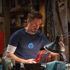
Lights, they can be, generally, they have analog values, the brightness has an analog value. So youcan take a light and have a dimmer switch connected to it and make it a little brighter or a little darker, right, and depending on how fine your control is you can have a lot of possible values between totally off and totally on. And it's a smooth transition, you can hit every possible value between completely dark versus completely bright by turning your dimmer switch. So in this way, light is generally an analog phenomenon. Also sound, you can see the same thing there. Sound I'm talking, right. I can talk quietly;I can talk loudly. I can talk in between. So I can adjust my volume any where in between completely quiet and completely loud. Again, sound is an analog phenomenon.
3.1.2 Digital signal
Now, digital phenomena are something that's either off or on, or at least has some discrete number of states. So for instance these lights, I could just hook them to a switch. They're wall switches, right? I hit off and the whole thing goes off, or it goes on, right? So maybe I'm using my light in a digital way. It's either all off or all on.
3.1.3 Analog to Digital Conversion
- Converts analog data to digital data
- Used to interface with analog sensors
Now the reason we bring this up is because these embedded systems are interacting with the real world. And the real world, to our perceptions, is largely analog. Now the problem with this is that our systems, the microcontrollers that we have, they are digital systems. So, they only understand digital data, specifically zeroes and ones, that's binary data. In order for our program on our microcontroller to be able to use information from sensors, that analog signal has been converted to a digital value. And that is what analog to digital conversion is for.
How it's performed A/D conversion is a complicated thing, but just understands that what it does is it takes an analog value and converts it to a digital number.
Push button: naturally digital sensor
3.1.4 Digital to Analog Conversion
Now on the output end, you usually need digital to analog conversion, or you often need digital to analog conversion. So let's say I have a microcontroller and it's outputting some sound to some speakers. These speakers are analog devices, they need analog signal. But the microcontroller is outputting zeros and ones,so you need digital to analog conversion to take those digital signals, convert them to analog and then drive the speaker with them.
- Converts digital signals to analog signals
- Used to interface with analog actuators
3.2 Basic Equipment
So in this lecture, we'll discuss some ofthe basic equipment that you're going to be using when you're building youri nternet of things devices.
3.2.1 A development board with a microcontroller the center of most projects
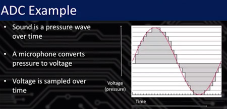
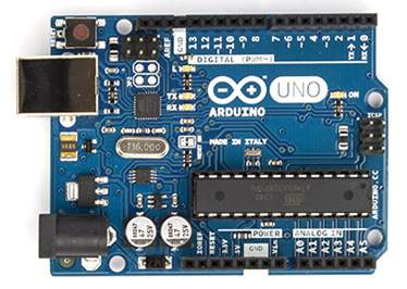
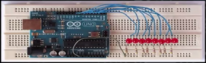
So first, the main thing we're going to useis a development board of some kind. It's a board that has a microcontroller on it, which is, of course, the center of all these projects. The center of these systems is going to be some microcontroller with some coderunning on it. So, the picture that we have here, is actually an arduino board. We're gonna take these development boards, plug them in by USB to our host, ourlaptop, desktop. Write code on the laptop, desktop. Program it onto the microcontroller on the development board.
3.2.2 Connectors: USB, Ethernet cable, jumper wires
Other equipment you're gonna get is USB cable, clearly, just to connect the board up. Ethernet cable is a common pieceof equipment I dont know if we'll be using that. But ethernet is common becausea lot of these boards have ethernet cables, have ethernet jacks because we wantthem to be networked.
3.2.3 Inputs: Potentiometer, Photoresistor, Keypad, LEDs, Ristors
Potentiometer. Potentiometer is a sensor that senses how much turn, sense of rotation. So if you turn something more, turn to the left, turn to the right,it changes the resistance between two signals. And you can use that as a rotation sensor. So if you wanna implement avolume knob or something like that, you can use apotentiometer and sense how much it's turned.
Photoresistor. Photoresistor is something that senses the brightness. So the brightness of the light will change the resistance on a certain resistor, and you can sense that. A keypad, that's another common component, just a bunch of buttons put together. Buttons, individual buttons, that's another input and common piece of equipment, and we'll have some of these.
Keypad. A keypad, that's another common component, just a bunch of buttons put together. Buttons,individual buttons, that's another input and common piece of equipment, andwe'll have some of these.
LEDs. Some of the outputs, LEDs, so those are light emitting diodes, you've seen those little lights that turn off and on, light emitting diodes.
Resistors. Resistors, we'll talk about those later, they don't do much.
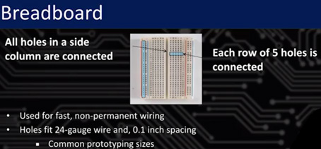
Breadboard. So breadboards are for wiring. So we're going to have a bunch of these components and we're going to need to connect these components together. So how do we connect them? Well there are several ways.
Soldering is morepermanent. In the end, when you're done, you know everything works, and then you might solder things together. But we're not inthat mode, we're gonna be using a breadboard.Breadboardis for non-permanent wiring. So basically it's got a bunch of holes, aboard with a bunch of holes. And these holes fit 24 gauge wire, which is the common wire size for components like this. And these holes are connected electrically. There are rows of five holes, you can see there, and if you put a wire into one hole in a row of five, all the other holes in the same row of five are connected. So you can plug two wires into two different holes on the same row of five and they are connected.
These two columns on the left, two columns on the right, with breaks in between. So those columns are not wired horizontally like those rows of five.They're wired in columns. So those two columns on the left, all holes in the same column are connected to each other, and all holes in the next column are connected to eachother. So traditionally those columns are used for power and ground because usually when you make a system, you have a lot of chips and alot of different components in there and a lot of them need to receive power and need to be connected to ground, so it helps to distribute power and ground across the whole circuit to just put power and ground into those rows, those columns, rather. So, put power into one column. Ground into another.


 被折叠的 条评论
为什么被折叠?
被折叠的 条评论
为什么被折叠?
 到【灌水乐园】发言


