This series of articles are the study notes of "Interfacing with the Arduino", by Prof. Harris, Department of Computer Science, University of California, Irvine. This article is the notes of week 2, lessen 1.
1. Lesson 1
1.1 Lecture 1.1 -Sensors
1.1.1 Sensors
(1) Allow the microcontroller to receive information about the environment
- How bright is it?
- How loud is it?
- How humid is it?
- Is the button being pressed?
So, IOT devices, embedded devices in general, have sets of Sensors. Sensors are the inputs to your device. So Sensors are how the device perceives the outside world. So it allows the microcontroller, which we have in the microcontroller on the Arduino, allows it to receive information from the outside world, about the environment.
(2) Perform operations based on the state of the environment
So, say I wanted to detect the humidity. Maybe I wanna do something if it's very humid out I need to do something. So I receive the humidity and I have some codes that says if humidity is above whatever the thresholds then do my operations. Something like that. So Sensors and these are just a few of the types of Sensors that exist. There are lots of Sensors. But somehow, how do we know the microcontroller has received received data from the Sensors? Because it needs to perform different operations based on some aspects of the environment.
(3) Turn on a light if it’s dark out
So, for instance turning a light out, turning a light on and it's dark out cuz it senses that the light outside is too low, meant that the light is too low, maybe it turns on a light, a very simple thing.
(4) Voice control operation
Or a voice controlled operation, so if somebody's speaking then it does an operation, right? So it receives a sound, if sound's above a threshold and matches a certain pattern then it performs an operation, things like this.
1.1.2 Sensing the Environment
(1) Microcontroller sense voltage
So when it comes to sensing the environment, eventually all this data has to come into the microcontroller. Because remember that in our system there's hardware, but the intelligence of the whole system is in this software, this code that you are writing. And this code is running on the microcontroller. So eventually this Sensor data has to come into the microcontroller and then your code has to interpret it, has to say, oh, if this light magnitude is greater than this, then do something.
But the thing about microcontrollers is that
they only sense voltage. That's all they can generally sense.
- digitalRead(pin); returns state of a digital pin
This digital read you give it a pin number and that returns the state of the digital pen. It returns if it's low or if it's high. So that is the Arduino reading the voltage on the pen. Right, so, this one I'm saying that the Arduino it is only any microcontroller is gonna read voltage. It can read digitally, either low or high.
- analogRead(pin); returns state of a analog voltage on a pin
Or you can use analogRead on the analog pins anyway. And that reads the analog voltage on a pin. But either way, either digital read or analog read you are reading the voltage on this pin.
(2) Sensor logic must convert an environment effect into voltage
But that's all the micro control can do to receive input. It can read voltages on pins. That's not all but that's the main way of the microcontroller is going to receive data, at least certainly at this stage. Receive data from our Sensors is through these pins and it's reading voltage values. So, in order for this to work, in order for Sensors to be able to send data to an Arduino or any other microcontroller, that
Sensor has to take whatever the environmental effect is that it's measuring, and turn that into a voltage value. So that the Arduino can read it.
So for instance, actually do I have an example? Actually, before I go on, one example that I might use, I might talk about
a light sensor, photo sensor. A photo sensor, maybe it's outputting the voltage according to how bright it is. You' would like to have a component like, your Sensor has to do that.
To take the brightness and turn it into a voltage, then it can drive that voltage up to a pin of the Arduino. Then in your Arduino code you can call analog read, see what the voltage is, and then you know how bright it is. So that's what all these Sensors are doing.
They're taking some environmental effect and turning it into voltage. So some of these Sensors, actually we'll go through some of these Sensors now.
(3) Some of the Sensor change resistance or do other things
Some of these Sensors do not directly do that.
A lot of these Sensors they don't output voltage. Some of these Sensors change resistance or do other things. And so it's up to you
to make a little circuit that changes, that causes a change in the environment to make a change in voltage.
1.1.3 Example of push button
So, take an example of push button. Now, remember a push button, all it does is connect two points, two wires right? So this push button, this simple push button it's got two terminals. When the button's not pushed, these terminals are not connected. When you push, close the button, close the switch by pushing the button. The two terminals are connected. So you have to, if you want your Arduino to read that push button, you've gotta make a circuit so that when they push this button and when you don't push this button, it changes the voltage on a pin of the Arduino.
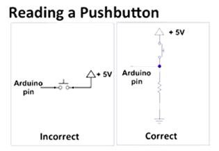
(1) Make a pin high when the button is pressed, and low when it is not pressed
So, up here on the slide we've got two circuits, the incorrect version and the correct version. Now, let me tell you our goal here in our circuit. We need to make a pin go high when the button is pressed and go low when the button is not pressed. That's our whole goal. If we can do that, then inside our code we can call digital read and we can see if it's low or high and see if the button is pressed or not.
(2) Incorrect circuit leaves pin open when not pressed
Now the incorrect circuit is a sort of a first cut, You can take some Arduino pin, and you can wire that to one side of the push button. Then on the other side of the push button you can take that and wire that to plus five volts to power.
Now This is half good.
This is good in the sense that when you press the button, the Arduino pin is then directly connected to the five volts.
That's half of what we wanted. But the other half of what we wanted is that
the Arduino pin should be low when the button is not pressed. And that incorrect circuit does not accomplish that.
When the button is not pressed, the Arduino pin isn't connected to anything.So
its voltage can float between high and low. We don't know what its voltage is.
(3) Correct circuit
A better circuit is the correct one. So if you look at the correct one, we wired this Arduino pin in between a resistor and a push button. Let's look at what happens when you press the button. When you press the button, you connected the Arduino pin directly to five volts.
You connect the Arduino pin directly to five volts and we're happy, right? Because the Arduino pin's connected to five volts so when you press the button the Arduino pin reads high.
And notice that the current flow will go from power straight to ground through that resistors. You've got resistors down there. Now a little bit of current will flow into the Arduino pen, but only very little. The majority of the current will go straight from power to ground. These Arduino pins are made not to take too much current.
So sometimes with these simple circuits, with simple Sensors, rather, you have to build a little circuit around the Sensor just to make it change voltage so that you can read it in the Arduino.
1.2 Lecture 1.2 -Resistive Sensors
1.2.1 Resistive Sensors
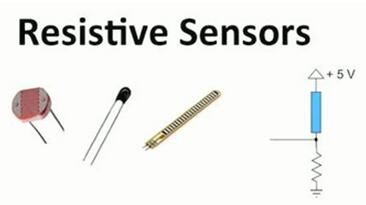
(1) Many sensorschange resistance
There are several different types of sensors. Right now we'll talk about some simple sensors. And a lot of simple sensors we'll call Resistive Sensors. What they do is they change resistance, so they act like resistors. Butthey are resistors whoes resist changes according to some environmental effect.
That first one, the one all the way on the left, that's a Photoresistor. So it just,
its resistance changes according to the brightness, in the room. T
he resistor of Photoresistor becomes bigger when the light goes dark. So the voltage of Photoresistor goes up as the resistor becomes bigger.
The next one is the Thermistor, so its resistance changes according to the temperature.
And the next one is Flex Resistor and it bends and its resistance changes according to how much it's bent. If it's bent a lot then it has a different resistance than if it's straight.
So these are all three sensors. They sense things about the environment, and the way sense, the way they transmit information is by changing a resistance. So remember that our microcontroller, it doesn't sense resistance directly, it senses voltage. So we've got to make this, put this thing inside a circuit.
In that circuit there has to be a voltage which changes when the resistance of this sensor changes.
(2) Connected sensor in a voltage divider
And the circuit has got, it's basically a voltage divider. So at the bottom its got a resistor going to ground. At the top it has this blue box. Right? This blue box is gonna be a sensor, one of these resistive sensors. So it could be a photoresistor, it could be a thermistor, it could be a flex resistor, it could be any of those. As long as they are, they basically act as resistors up there. And the resistances changes according to the environmental effect that you wanna observe.
(3) As resistance changes, voltage changes
This circuit is like potentiometers which I showed as a voltage divider. It's got two terminals on the top and the bottom, and then it's got this middle terminal between two resistors. And these resistors, their ratio, the ratio of their resistance, can change in a potentiometer. Similar things happening here. The bottom resistor is just gonna be constant. Okay, but the bottom resistor is this sensor. And that changes according to the brightness, let’s say of the photoresistor. Or the temperature of the thermistor. And so you see between the two resistors you got that point there that we're observing, that's connected to, say, and Arduino pin.
We're going to observe the voltage at that point. And that voltage will go up and down according to the resistance on that resistor.
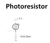
1.2.2 Photoresistor
- As brightness increases, the resistance of the photoresistor decreases
Here’s an example, you might have a photoresistor, so you can see, that's the voltage divider. The bottom resistor, I've made 10 kilo ohms, and the top resistor, I have made a photoresistor. That's the symbol for photoresistor. It's basically a resistor with a circle around it, got some arrows coming in, cuz it's detecting light. And so, it's a voltage divider, and let's say that this voltage divider, this photoresistor, its resistance changes within a range depending on the brightness. So, as brightness increases, the resistance of the photoresistor decreases. That's generally how they work. So, I'm making up some numbers here, but let's say its resistance is 10 K Ohms at a certain level of brightness. Okay, so at 10 K Ohms then that means if we look at our volts divider we've got a 10 K Ohms resistance on the top and a 10 K Ohms resistance on the bottom, which means that the voltage will be divided in half. So since you've got five volts going from top to bottom, five volts on the top, zero on the bottom that middle point that we're measuring will be 2.5 volts, because the resistance are even.
But let's say the brightness changes.Let's say it gets more bright, then the resistance goes down. So now the resistance of the photoresistor is only 5 K Ohms. Now when that happens, you've got a smaller resistor on top and still got the big 10 K Ohm resistor on the bottom. Right? So now, what happens is since there's less resistance on top, there's gonna be less voltage, what's called voltage drop, voltage difference across the top resistor. So now, the resistance that we measure, the voltage that we measure in between those two resistors is gonna be higher, 3.3 volts.
So the point there is that as the outside environmental, environment changes. So, in this case, if it's a photoresistor, the brightness changes. The resistance changes in this circuit, and as the resistance changes the voltage changes on that pin that we're measuring. And that pin that's going into one of the analog inputs of the Arduino.
And we can measure that with an analog read. So by calling analog read we can see the voltage value, and we can detect the change. And we can make something, some code that does something activates some device when the light level goes above a certain threshold. If the voltage that we measure is higher than X then we can do something. So, we can write code that reacts to the environment.
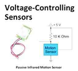
1.2.3 Voltage-Controlling Sensors
there are some other sensors that are a little bit more complicated, but actually easier to use from our perspective. Voltage-Controlling Sensors. In these devices, they don't output resistance. Instead they have a pin which outputs a certain voltage directly. This is good for us because Arduino, it directly senses voltage.
(1) PIR motion sensor
PIR standing for
Passive Infrared motion sensor. So that's what I have over there in the left. You see that passive infrared motion sensor. And yeah, actually, you've probably seen these things like this. This is what you would have, like we have in this room actually, and in a room in my office. This is a motion sensor so when you come in the room the lights go on, something like that.
PIR motion sensor has three leads, three wires, three terminals. One is connected to power, one is connected to ground, and one is the signal that you're interested in, the voltage that you're interested in.
So, if we look at our motion sensor block over there, it's got one pin on the top, one pin on the bottom and one pin on the right side. So the pin on the bottom that's wired straight to ground. The pin on the right that's wired straight to power. Okay, the pin on the top is the one that you can see. If you follow the pin on the top that goes to the left, which is presumably going to our Arduino.
And the way this motion sensor works, is if, actually this particular motion sensor, what it does is, it pulls the signal low when motion is detected. So when it senses motion, it sets that voltage on top to zero volts. Okay, so that's what's gonna happen. Now, when it doesn't sense motion, it doesn't do anything to that wire on top. Right? So that wire, the voltage on that wire would be floating. So that's why we need a 10 K Ohm resistor to power, because if there's no motion then we don't want, one thing that we'd never want to input to our server is a floating voltage. We don't want a floating voltage, so we wanna make sure that, if there's no motion, even though the motion sensor isn't assigning a value to this pin, this wire gets some value. Right? And that value that it gets in this case should be a one, should be a high voltage. Because the low is what happens when there's motion, so we want high to be associated with no motion.
(2) voltage-controlling sensor
This is one type of sensor, it's a voltage-controlling sensor. They're useful. They're nice to use. They're pretty easy to make the circuit to use them. This is just one. There are several, it's called Open-Collector. So when you have a pin like that you pull low and it floats when there's no motion. They call that open-collector, so we have to pull it high it needs it's pull up resistor. So that when there's no motion it goes to high it has a known value.
(3) Accelerometer
Okay, so there are lots of different type of sensors that are voltage controlling, and here's a couple. The first one, the one over there on the left is the Triple Access Analog Accelerometer. So, an accelerometer basically senses acceleration in three dimensions, so X, Y, Z, it'll tell you the acceleration.
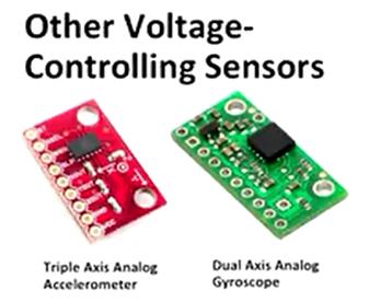
- Accelerator reports acceleration in 3 dimensions
So this is useful for telling your orientation. Because there's always the acceleration of gravity. So you can tell the orientation of your device based on what this, this thing reports back. If it reports basically, and you know what gravitational pull is supposed to be, what it's acceleration is. So you can measure your acceleration in each axis and tell what it's orientation is.
it has those holes on the side of that little board. You generally solder pins onto those, it was called a Breakaway board. And you solder those pins on there and then you can wire those pins into the Arduino and sense the voltage on those pins. And there are several of them, but one is X, one is Y, one is Z. Those are the signals of interest. And you can wire those into the analog input of the Arduino and tell what the acceleration is in each axis.
(4) Dual Axis Gyroscope
- Gyroscope reports angular velocity in 2 dimensions
The next one is the Dual Axis Gyroscope. So a gyroscope actually reports angular velocity. In only two dimensions this time. But again, there are two signals in there that you can read and see what the angular velocity is. Now both of these type of things, these are used in any kind of device that needs to sense orientation. The two of them are used together, actually. So, for instance, my quadcopters. They all have these built into them. Accelerometers and Gyroscopes are essential, because it needs to know its orientation so it can stay level. So, these type of devices are commonly used for that type of application.
1.3 Lecture 1.3 -Resistive Sensor Demo
1.3.1 Resistive Sensors
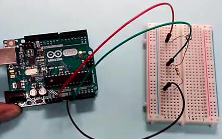
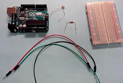
Next, we're looking at resistive sensors. We're going to attach a resistive sensor to the Arduino, read its value, and blink an LED. So, for your reference, the program on the Arduino here that were going to be running is called Analog Input. So if you look under examples in the Arduino IDE, you go to examples, under Analog, Analog Input. And what that does is, it reads the analog voltage supplied in A0, which is right here. Resit voltage and, according to that voltage, it changes the rate at which the LED will blink.


 被折叠的 条评论
为什么被折叠?
被折叠的 条评论
为什么被折叠?
 到【灌水乐园】发言


