


 本文介绍如何从Blender导出3D模型至OpenGLES,并使用Xcode构建命令行工具解析OBJ文件,最终实现在iOS应用中显示带纹理和光照效果的3D模型。
https://www.raywenderlich.com/48293/how-to-export-blender-models-to-opengl-es-part-1
https://www.raywenderlich.com/50398/opengl-es-transformations-gestures
Recently, we published Blender tutorial for beginners that showed you how to create your own 3D models in Blender.
But you might be wondering – how can I export Blender models to OpenGL ES?
That’s what this epic three-part tutorial series is all about! You will learn how to make an awesome 3D model viewer for iOS that can display models that you create in Blender.
Here’s how the series will be organized:
- Part 1: Welcome! You’ll start by learning about one of the simplest formats that Blender can export models to – the OBJ file format. Then you will create a general command line tool to parse this file format and generate suitable arrays in C source code for OpenGL ES. You’ll use a cube as an example shape.
- Part 2: In the next part, you’ll learn about the MTL material definition and file format, and then you’ll use this information to add Blender materials to your cube.
- Part 3: In the final part, you’ll implement a simple lighting model for your 3D scene by writing your own OpenGL ES shaders!
This tutorial series assumes you are familiar with OpenGL ES 2.0 and GLKit. If you are new to these or need a refresher, you should first read our tutorial series Beginning OpenGL ES 2.0 with GLKit (required) and OpenGL ES 2.0 for iPhone Tutorial (recommended). Basic knowledge of C++ (or at least C) is also assumed.
This is NOT a Blender or modeling tutorial (see our previous tutorial for that), but each section on Blender has a detailed walkthrough. If you haven’t done so yet, you can download a free copy of Blender here. I recommend version 2.62 if you want the best chance to follow along exactly with the tutorial project. Install it and let’s go!
Getting Started
First, download the starter pack for this tutorial. The contents are grouped as follows:
- /Blender/: This folder contains your Blender scene (cube.blend) and associated texture (/textures/cube.png).
- /Code/: Later on, you will create two separate Xcode projects here—one for your command line tool and one for your iOS app.
- /Resources/: This folder contains all of your model’s files required by OpenGL ES. At the moment you’ll only see cube.png, but you’ll add more files as you go along.
Since this tutorial has many separate components, I recommend you keep your directory organized as such for easy navigation.
A Simple Blender Cube
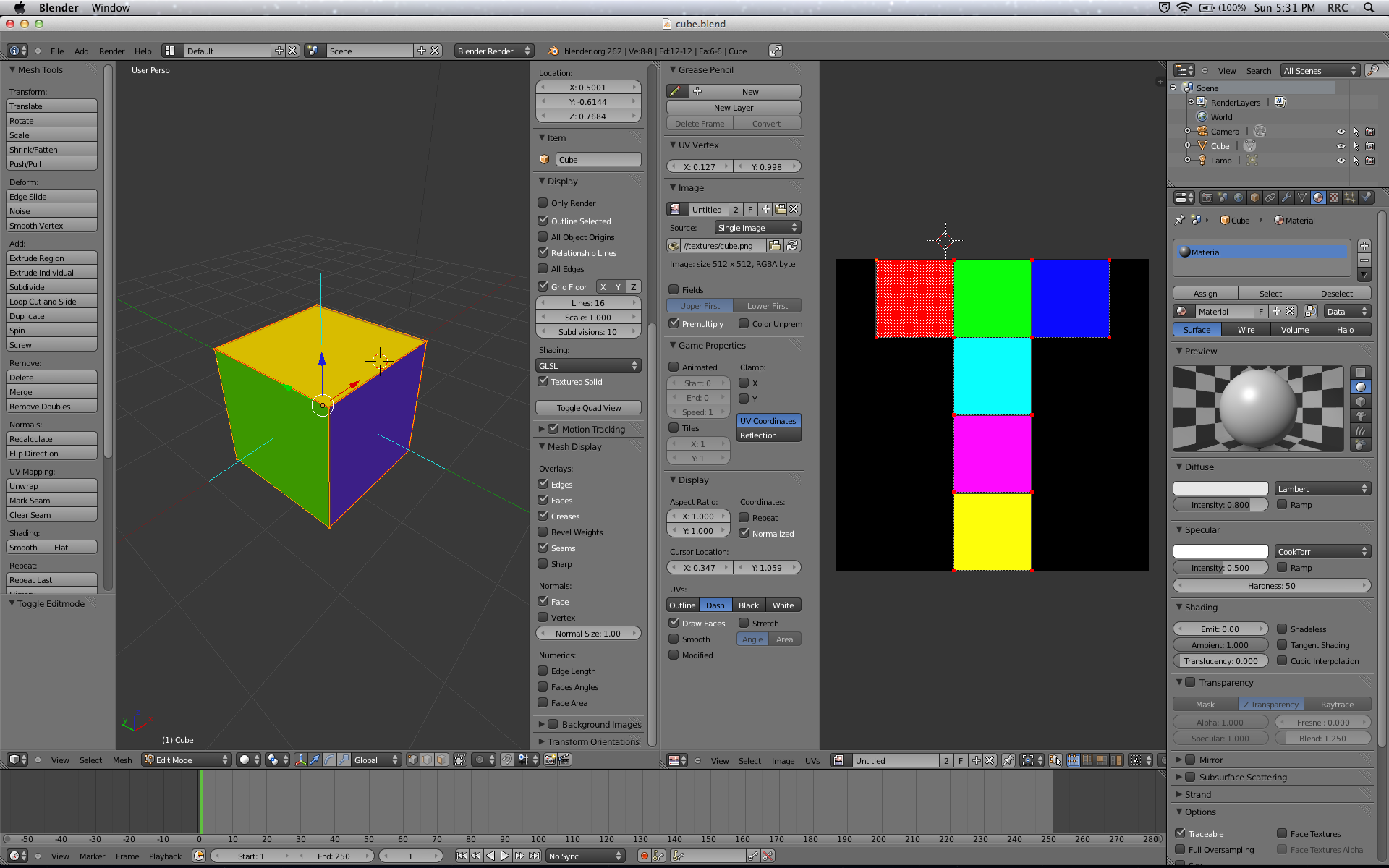
Launch Blender and open cube.blend. Feel free to explore the scene if you’d like, but what you have here is simply the default Blender cube all textured and ready to export. It should look something like this:
You can modify the scene or use your own models at the end of the tutorial, but for now it’s important you stick to the basics in order to fully understand the back-end of 3D objects. If you want to make things more interesting, you can always pretend this is a model of the Wisdom Cube.
The OBJ File Format
3D content exists in several different file formats, with one of the most popular being the .obj definition developed by Wavefront Technologies (now owned by Autodesk). This file format has stood the test of time because it’s open, cross-platform and simple. COLLADA (.dae) is a newer and improved XML-style format that has some similarities to OBJ and is making a big push into the market, but OBJ is here to stay. Blender, Maya, ZBrush and many other graphics and modeling products support OBJ.
The OBJ representation contains geometry data for a 3D model based on vertices. This data is split into the following categories:
- Vertex (v): The position of the vertex in XYZ space.
- Texture Coordinates (vt): The texel (texture element) to sample in UV space. You can think of this as a way to map each vertex to the position on the texture where it should get its color value from. These values range from (0, 0) (bottom left of texture) to (1, 1) (upper right of texture).
- Normals (vn): The surface normal of the vertex plane (triangle) in XYZ space. You can think of this as the vector that points “straight out” from the front of the plane at the vertex. This value is needed to ensure proper lighting.
- Faces (f): A plane triangle defined by three vertices, texture coordinates and normals.
Note: Unlike OpenGL, the OpenGL ES API doesn’t allow rendering with quads (GL_QUADS), so you’ll have to export your model as a set of triangles. This is arguably a better approach anyway, since GPUs are optimized to render triangles—it’s definitely not a disadvantage of OpenGL ES.
I will explain each attribute in detail shortly, but first familiarize yourself with their representation in Blender by taking a look at the image below.

Awesome! Now that you’re familiar with the basics, it’s time to export your cube.
Exporting an OBJ From Blender
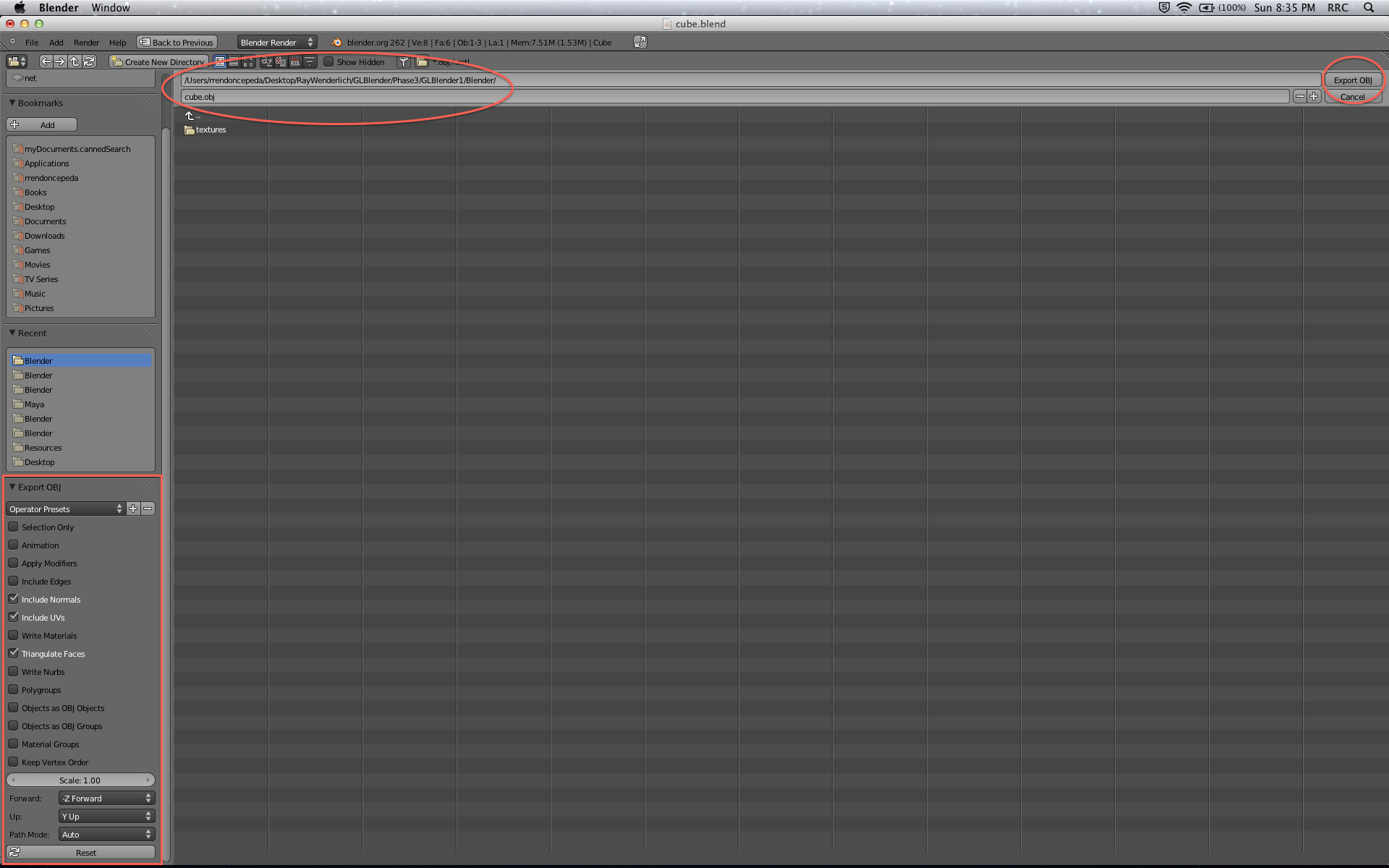
In Blender, with cube.blend open, go to File\Export\Wavefront (.obj). An export screen with many options will appear. Check the following boxes:
- Include Normals
- Include UVs
- Triangulate Faces
Uncheck all other boxes and leave the remaining fields in their default state. Name your file cube.objand click Export OBJ. You may export or copy your OBJ file to your /Resources/ folder if you wish.
Your cube OBJ is ready! That’s all you need from Blender for now, so you may close the application.
Analyzing Your OBJ File
Before you continue, it’s time for a challenge! Given the information about OBJ files and the geometry of the cube, can you guess how many attributes there will be for each of vertices (v), texture coordinates (vt), normals (vn) and faces (f)?
Hint: A cube has 6 square faces, but each square is made up of two triangles…
| Solution Inside: Cube Geometry Attributes | Show |
|---|---|
Using a text editor such as TextEdit, open up cube.obj. Its contents should look like this.
Note: Blender has some known floating point precision errors, so don’t worry if your numbers are a little off in the last few decimal places—for example, vertices #5 and #6 should actually be rounded out to a clean +/- 1.0. Similarly, if some lines are in a different order from the example given, this could be an equivalent representation of the same object, so that’s fine.
However, these floating point errors can also lead to spurious, additional vertices, as Blender mistakenly generates data structures representing two vertices that differ only by a floating point error. This kind of output might make it harder to follow the rest of the tutorial since you will see different counts of data structures parsed.
If you want the best chance of matching the exact output in this tutorial, use Blender version 2.62. The important thing is that your faces (f) match the solution above. If they don’t, try opening up an unmodified cube.blend file and exporting the OBJ file again. If it’s still not working, just replace your OBJ file with the one above.
As you can see, OBJ files are well-organized and easy to read. Their generic structure for your export settings is:
# List of vertices (v) with XYZ coordinates.
v  1.0x   1.0y   1.0z
v  ...X   ...Y   ...Z

# List of texture coordinates (vt) with UV coordinates.
vt 0.5u   0.5v
vt ...U   ...V

# List of normals (vn) with XYZ coordinates.
vn 0.0x   1.0y   0.0z
vn ...X   ...Y   ...Z

# List of faces (f) with v, vt, and vn data (three points ABC per face).
f  1v/1vt/1vn   2v/2vt/1vn   3v/3vt/1vn
f  v/vt/vnA     v/vt/vnB     v/vt/vnC
Using the texture cube.png for visual aid, this is what the OBJ data represents (shown for ease of comprehension, not in order of the file output):

- Vertices (v): These are the corners of the cube, shared amongst many faces, where edges meet each other in 3D. If you were to fold up the 2D texture into a 3D cube and attach all the seams properly, you would have 8 vertices—the detached corners in the image above would actually share one of the marked vertices.
- Texture Coordinates (vt): These are the points defining the edges of the textures themselves, if you unwrapped the 3D cube and laid it out flat in 2D. Some textures that adjoin in 3D will also adjoin in 2D, so they still share corners. Other textures that adjoin in 3D will be separate in 2D, producing additional corners, so now these corners need additional coordinates to represent them. If you add it up, looking at the above diagram, you get 14 texture coordinates. If there was no overlap between any of the squares, you would have 24 texture coordinates (6 squares * 4 corners).
- Normals (vn): Normals are for the normal vectors, mathematical structures that point directly away from a point on a surface and thus describe how that surface is oriented in space. For this simple cube, a pair of triangles renders each of the six sides. As each triangle lies side-by-side with its partner on the same plane, they share the same normal, so you only need 6 normals in total to define the cube. You can read more about normals here.
- Faces (f): As mentioned before, OpenGL ES can render triangles but not quads. So every square side of the cube is broken up into two triangles, leaving you with 12 faces.
These counts are for the number of distinct values needed to describe this particular shape, a cube, and would be different for a different shape. So you will need to design your tool to work with the general defining relationships between these geometry elements, while checking it by verifying that the code it generates to describe a cube uses the specific above values.
Phew, that’s a lot of new information! Now that you know how 3D models are exported with Blender and represented by OBJ, it’s time to parse this data for OpenGL ES. That’s right, time to code! Feel free to take a well-deserved break, though.
Building an OBJ to OpenGL ES Command Line Tool
The tool you will build throughout this tutorial series is based on mtl2opengl, a parser I developed as an extension to obj2opengl. Both tools are Perl scripts that you should definitely check out later, but right now you’ll be using Xcode and C++ to take care of business. :]
Project Setup
Open Xcode and go to File\New\Project…. Select OS X\Application\Command Line Tool and click Next.

Name your project blender2opengles, select C++ for Type, make sure Use Automatic Reference Counting is checked and click Next.

Save your project inside the folder /Code/ and click Create. In your new project, open main.cpp, give it a look and then build and run it. A “Hello, World!” message will be output to your console—classic.
Project Directory
Command line tools keep their products and data outside of their Xcode project directory. You don’t need to pull this hidden directory, but you’ll have a much easier time managing your model files if you keep them within sight and reach.
In Xcode, go to Product\Scheme\Edit Scheme…. Click on the Options tab, check the box labeled Use custom working directory:, type ${PROJECT_DIR} into the text field and click OK. Any file references in your program will now default to your Xcode project’s path.

Using Finder, open your project directory (/Code/blender2opengles/) and create two new folders, source and product. Copy your model file cube.obj into the new source folder. Your project now has a very clean directory to reference.

Input/Output, Files and Strings
Speaking of file handling, now’s a good time to add the C++ Standard Library classes necessary for this project. Add the following lines to the top of main.cpp:
// C++ Standard Library
#include <iostream>
#include <fstream>
#include <string>
using namespace std;
These classes enable you to work with input/output, files and strings. The std:: prefix is also accounted for, so remove it from the cout line to leave:
cout << "Hello, World!\n";
Build and run again! Your console output will be the same, but you’ve just saved yourself from writing hundreds of std:: statements when dealing with input/output, files or strings. Maybe you should change your message to, “Hello, Optimization!” On second thought, remove the “Hello, World!” output now.
Command Line Arguments
To make your tool reusable, you’re going to design it in such a way that it can take in command line arguments for any OBJ file simply by specifying the file name, minus the .obj extension.
Go to Product\Scheme\Edit Scheme... and click on the Arguments tab. In the section titled Arguments Passed On Launch, click the + sign, type in cube and then click OK.

Back in main.cpp, add the following lines to main():
// Arguments
cout << argc << endl;
cout << argv[0] << endl;
cout << argv[1] << endl;
Build and run! The console now shows your argument list:

The top line outputs the number of arguments (2), with the first being the blender2opengles product directory on your computer (ugly, isn’t it?) and the second one being the model name you declared (cube).
Add the following lines just below the new code:
// Files
string nameOBJ = argv[1];
string filepathOBJ = "source/" + nameOBJ + ".obj";
string filepathH = "product/" + nameOBJ + ".h";
string filepathC = "product/" + nameOBJ + ".c";
You now have references to your cube input (cube.obj) and output (cube.h, cube.c) files. You’ve completed your command line tool setup!
The Model Info
After your deep dive into the OBJ file format, you know that you can define your model as a list of vertices with positions, texels, and normals grouped into faces. Each attribute needs its own array, for which you need to find the size by reading through the OBJ file once, so let’s write some code to store the results.
In main.cpp, after the using directive, add the following lines to define the typedef Model:
// Model Structure
typedef struct Model
{
    int vertices;
    int positions;
    int texels;
    int normals;
    int faces;
}
Model;
Each field in Model holds the number of elements for each attribute and thus defines their array size. Now let's write a function to actually read the OBJ file.
In main.cpp, just after your typedef statement, add the following function definition for getOBJinfo:
// 1
Model getOBJinfo(string fp)
{
    // 2
    Model model = {0};

    // 3
    // Open OBJ file
    ifstream inOBJ;
    inOBJ.open(fp);
    if(!inOBJ.good())
    {
        cout << "ERROR OPENING OBJ FILE" << endl;
        exit(1);
    }

    // 4
    // Read OBJ file
    while(!inOBJ.eof())
    {
        // 5
        string line;
        getline(inOBJ, line);
        string type = line.substr(0,2);

        // 6
        if(type.compare("v ") == 0)
            model.positions++;
        else if(type.compare("vt") == 0)
            model.texels++;
        else if(type.compare("vn") == 0)
            model.normals++;
        else if(type.compare("f ") == 0)
            model.faces++;
    }

    // 7
    model.vertices = model.faces*3;

    // 8
    // Close OBJ file
    inOBJ.close();

    // 9
    return model;
}
The function above has many parts worth explaining, so let’s break it down:
-
fpis the path of your OBJ file. - This line creates a new instance of
Modelinitialized to0. -
ifstreamopens your OBJ file for reading (input). - You read through your OBJ file from start to finish.
- After analyzing an OBJ file manually, you know you’re looking for lines starting with
v,vt,vnorf, so the first token to parse will have a maximum of two characters. - You compare this two-character token to the line prefixes listed above, increasing the counter for
positions,texels,normalsorfacesif there is a match. - Even though a 3D model has shared vertex data, in this tutorial OpenGL ES will process all vertices individually instead of as indexed arrays. You already know that OpenGL ES draws triangles, so the total number of vertices will be the total number of faces times their three defining points.
- You close your OBJ file.
- Finally, you return your
Modelinformation.
Awesome—let’s move along. Add the following lines to main():
// Model Info
Model model = getOBJinfo(filepathOBJ);
cout << "Model Info" << endl;
cout << "Positions: " << model.positions << endl;
cout << "Texels: " << model.texels << endl;
cout << "Normals: " << model.normals << endl;
cout << "Faces: " << model.faces << endl;
cout << "Vertices: " << model.vertices << endl;
Build and run! You should already know what to expect, but it’s nice to have your console confirm your expectations.

The Model Data
Now that you know your model attribute sizes, it’s time to create the dedicated data arrays. Add the following lines to main():
// Model Data
float positions[model.positions][3];    // XYZ
float texels[model.texels][2];          // UV
float normals[model.normals][3];        // XYZ
int faces[model.faces][9];              // PTN PTN PTN
Each 2D array fits the exact number of attributes with the following data:
-
positions[][3]: three floats, one for each coordinate in the XYZ space. -
texels[][2]: two floats, one for each coordinate in the UV space. -
normals[][3]: three floats, for a vector in the XYZ space. -
faces[][9]: nine integers, to describe the three vertices of a triangular face, where each vertex gets three indexes, one for its position (P), one for its texel (T) and one for its normal (N).
Please note that the above values defining your data model do not depend on the specific cube shape at all. These values all follow directly from the basic definition of a vertex, texel, normal and triangular face.
Your next goal is to parse the cube’s data from the OBJ file into these arrays. Add the following function definition above main():
void extractOBJdata(string fp, float positions[][3], float texels[][2], float normals[][3], int faces[][9])
{
    // Counters
    int p = 0;
    int t = 0;
    int n = 0;
    int f = 0;

    // Open OBJ file
    ifstream inOBJ;
    inOBJ.open(fp);
    if(!inOBJ.good())
    {
        cout << "ERROR OPENING OBJ FILE" << endl;
        exit(1);
    }

    // Read OBJ file
    while(!inOBJ.eof())
    {
        string line;
        getline(inOBJ, line);
        string type = line.substr(0,2);

        // Positions
        if(type.compare("v ") == 0)
        {
        }

        // Texels
        else if(type.compare("vt") == 0)
        {
        }

        // Normals
        else if(type.compare("vn") == 0)
        {
        }

        // Faces
        else if(type.compare("f ") == 0)
        {
        }
    }

    // Close OBJ file
    inOBJ.close();
}
This new function is very similar to getOBJinfo() in the previous section, so take a moment to notice the differences and similarities.
Both functions read the OBJ file and parse each line looking for a type of geometry element. But instead of simply counting the element types by incrementing members of the model object, extractOBJinfo extracts and stores the whole data set for each attribute. To do this, it needs to handle each type of geometry element differently.
Let’s start with positions[][3]. Add the following code to extractOBJdata() to make the if conditional for your positions look like this:
// Positions
if(type.compare("v ") == 0)
{
    // 1
    // Copy line for parsing
    char* l = new char[line.size()+1];
    memcpy(l, line.c_str(), line.size()+1);

    // 2
    // Extract tokens
    strtok(l, " ");
    for(int i=0; i<3; i++)
        positions[p][i] = atof(strtok(NULL, " "));

    // 3
    // Wrap up
    delete[] l;
    p++;
}
This is only a little bit of code, but it’s tricky:
- Before parsing the current OBJ line, it’s best to create a working copy (
l) separate from the file being read. The+1accounts for the end-of-line character. Keep in mind that you are allocating memory here. -
strtok(l, “ “)tells your program to create a token fromlup to the first“ “character. Your program ignores the first token (“v”), but stores the next three (x, y, z) as floats inpositions[][3](typecast byatof()).strtok(NULL, “ “)simply tells the program to parse the next token, continuing from the previous string. - To wrap things up, you must deallocate your memory for
land increase the counterpforpositions[][3].
It’s short but powerful! A similar process follows for texels[][2], normals[][3] and faces[][9]. Can you complete the code on your own?
Hint #1: Pay close attention to each array size to figure out the number of tokens it expects to receive.
Hint #2: After the initial token “f”, the data for each face is separated by either a “ “ or a “/”character.
| Solution Inside: Parsing Attributes | Show |
|---|---|
You should feel very proud of yourself if you figured that one out! If you didn’t, I don’t blame you, especially if you are new to C++.
Moving on, add the following line to main():
extractOBJdata(filepathOBJ, positions, texels, normals, faces);
cout << "Model Data" << endl;
cout << "P1: " << positions[0][0] << "x " << positions[0][1] << "y " << positions[0][2] << "z" << endl;
cout << "T1: " << texels[0][0] << "u " << texels[0][1] << "v " << endl;
cout << "N1: " << normals[0][0] << "x " << normals[0][1] << "y " << normals[0][2] << "z" << endl;
cout << "F1v1: " << faces[0][0] << "p " << faces[0][1] << "t " << faces[0][2] << "n" << endl;
Build and run! The console shows the first entry for each attribute of your cube model. Make sure the output matches your cube.obj file.

Good job, you have successfully parsed your OBJ file!
Generating the Header File (.h)
OpenGL ES will read your Blender model as a collection of arrays. You could write all of these straight into a C header file, but this approach may cause trouble if you reference your model in more than one part of your app. So, you’re going to split the job into a header (.h) and an implementation (.c) file, with the header file containing the forward declarations for your arrays.
You already know how to read an existing file with C++, but now it’s time to create and write to a new file. Add the following function definition to main.cpp, above the definition of main():
// 1
void writeH(string fp, string name, Model model)
{
    // 2
    // Create H file
    ofstream outH;
    outH.open(fp);
    if(!outH.good())
    {
        cout << "ERROR CREATING H FILE" << endl;
        exit(1);
    }

    // 3
    // Write to H file
    outH << "// This is a .h file for the model: " << name << endl;
    outH << endl;

    // 4
    // Close H file
    outH.close();
}
This code snippet is very similar to the read implementation from before, but let’s go over each step to clarify the process:
-
fpis the path of your new H file, withnamebeing the name of your model andmodelcontaining its info. -
ofstreamopens your H file for writing (output). If no file exists atfp, a new file is created for you. - Much like
cout,outHwrites to your file in the same style. - Close your H file and you’re good to go!
Now add the following line inside the body of main():
// Write H file
writeH(filepathH, nameOBJ, model);
Then build and run! Using Finder, check your project directory for the new H file (/Code/blender2opengles/product/cube.h), which should look something like this:

Return to the function writeH() and add the following lines inside, just before you close the file:
// Write statistics
outH << "// Positions: " << model.positions << endl;
outH << "// Texels: " << model.texels << endl;
outH << "// Normals: " << model.normals << endl;
outH << "// Faces: " << model.faces << endl;
outH << "// Vertices: " << model.vertices << endl;
outH << endl;

// Write declarations
outH << "const int " << name << "Vertices;" << endl;
outH << "const float " << name << "Positions[" << model.vertices*3 << "];" << endl;
outH << "const float " << name << "Texels[" << model.vertices*2 << "];" << endl;
outH << "const float " << name << "Normals[" << model.vertices*3 << "];" << endl;
outH << endl;
The first set of statements simply adds useful statistics comments to your header file, for your reference. The second set declares your arrays. Remember that OpenGL ES needs to batch-process all 36 vertices for the cube (3 vertices * 12 faces) and that each attribute needs space for its own data—positions in XYZ, texels in UV and normals in XYZ.
Build and run! Open cube.h in Xcode and make sure it looks like this:
// This is a .h file for the model: cube

// Positions: 8
// Texels: 14
// Normals: 6
// Faces: 12
// Vertices: 36

const int cubeVertices;
const float cubePositions[108];
const float cubeTexels[72];
const float cubeNormals[108];
Looking good. ;]
Generating the Implementation File (.c)
The implementation file will do the heavy lifting of initializing your arrays with their OBJ data. There is considerably more code in this section than in the previous one, but now that you’re comfortable with the file output process, it should be a breeze the second time around!
Add the following function to main.cpp, just above main():
void writeCvertices(string fp, string name, Model model)
{
    // Create C file
    ofstream outC;
    outC.open(fp);
    if(!outC.good())
    {
        cout << "ERROR CREATING C FILE" << endl;
        exit(1);
    }

    // Write to C file
    outC << "// This is a .c file for the model: " << name << endl;
    outC << endl;

    // Header
    outC << "#include " << "\"" << name << ".h" << "\"" << endl;
    outC << endl;

    // Vertices
    outC << "const int " << name << "Vertices = " << model.vertices << ";" << endl;
    outC << endl;

    // Close C file
    outC.close();
}
Then, add the following line inside main():
// Write C file
writeCvertices(filepathC, nameOBJ, model);
This should all be familiar. It’s a very similar function to writeH(), except here you're writing an #includestatement and Vertices to your C file.
Build and run! Now locate cube.c in Finder and open it with Xcode—it should look like this:
// This is a .c file for the model: cube

#include "cube.h"

const int cubeVertices = 36;
Perfect! Now you may have noticed that you named the previous function writeCvertices() instead of just writeC(). This is because you'll be writing each attribute array separately! Many models are humongous, for example the classic Stanford Bunny with over 200,000 vertices. Sometimes a model doesn’t need a texture, or its normals may be computed by the importing program, so reducing their file size is a smart move.
Let’s start by writing out the model’s positions to your C file. Add the following function to main.cpp, just above main():
// 1
void writeCpositions(string fp, string name, Model model, int faces[][9], float positions[][3])
{
    // 2
    // Append C file
    ofstream outC;
    outC.open(fp, ios::app);

    // Positions
    outC << "const float " << name << "Positions[" << model.vertices*3 << "] = " << endl;
    outC << "{" << endl;
    for(int i=0; i<model.faces; i++)
    {
        // 3
        int vA = faces[i][0] - 1;
        int vB = faces[i][3] - 1;
        int vC = faces[i][6] - 1;

        // 4
        outC << positions[vA][0] << ", " << positions[vA][1] << ", " << positions[vA][2] << ", " << endl;
        outC << positions[vB][0] << ", " << positions[vB][1] << ", " << positions[vB][2] << ", " << endl;
        outC << positions[vC][0] << ", " << positions[vC][1] << ", " << positions[vC][2] << ", " << endl;
    }
    outC << "};" << endl;
    outC << endl;

    // Close C file
    outC.close();
}
Let’s break it down...
- At a first glance, it might seem odd to pass
faces[][9]into the function, but it is absolutely necessary. Recall that all 36 cube vertices must be written out, but there are only eight distinct positions for this particular model. The values infaces[][9]are actually an index to these positions, which are shared amongst many vertices. With 12 faces in total and three positions per face, all 36 vertex positions are accounted for. -
ofstreamopens the C file for writing (output), but this time in the append mode to avoid creating a new file and overwriting existing data. - Recall that faces in an OBJ file are stored in the order v/vt/vnA v/vt/vnB v/vt/vnC. Thus, indices
0,3and6offaces[][9]correspond tovA,vBandvC. You must then subtract1from the resulting index, because OBJ indices start from 1, not 0. - Finally, write the x-, y-, and z-position coordinates to your C file, for each point of a face.
Add the following statement inside main():
writeCpositions(filepathC, nameOBJ, model, faces, positions);
Build and run! Open cube.c in Xcode and you should see the following lines appended to your file:
const float cubePositions[108] =
{
1, -1, -1,
1, -1, 1,
-1, -1, 1,
1, -1, -1,
-1, -1, 1,
-1, -1, -1,
1, 1, -0.999999,
-1, 1, -1,
-1, 1, 1,
1, 1, -0.999999,
-1, 1, 1,
0.999999, 1, 1,
1, -1, -1,
1, 1, -0.999999,
0.999999, 1, 1,
1, -1, -1,
0.999999, 1, 1,
1, -1, 1,
1, -1, 1,
0.999999, 1, 1,
-1, 1, 1,
1, -1, 1,
-1, 1, 1,
-1, -1, 1,
-1, -1, 1,
-1, 1, 1,
-1, 1, -1,
-1, -1, 1,
-1, 1, -1,
-1, -1, -1,
1, 1, -0.999999,
1, -1, -1,
-1, -1, -1,
1, 1, -0.999999,
-1, -1, -1,
-1, 1, -1,
};
You’re doing a great job and you’re almost done. I hope that knowledge puts you in the mood for a challenge, because you should now be able to implement similar functions for texels (writeCtexels()) and normals (writeCnormals()). I know you can do it!
Hint: Use the function writeCpositions() as a starting template and add the new functions just above main().
| Solution Inside: Writing Attributes | Show |
|---|---|
Finally, add the following lines to main():
writeCtexels(filepathC, nameOBJ, model, faces, texels);
writeCnormals(filepathC, nameOBJ, model, faces, normals);
Build and run! Open cube.c in Xcode. Its contents should look like this:
Congratulations, your blender2opengles tool is complete and your Blender model is now compatible with OpenGL ES! Copy your files cube.h and cube.c into your /Resources/ folder. This was no easy feat, so you’ve earned yourself a pat on the back and a quick break before moving on. :]
Building the Model Viewer iOS App
And now, the moment you’ve been waiting for... the app!
Project Setup
Open Xcode and go to File\New\Project.... Select iOS\Application\Empty Application and click Next. Name your project GLBlender1, choose iPhone for device family, make sure Use Automatic Reference Counting is selected and click Next. Save your project inside the folder /Code/ and click Create.
You want this app to run in portrait orientation only, so click on your GLBlender1 project in the Project Navigator and select GLBlender1 under TARGETS. In the Summary tab, under Supported Interface Orientations, make sure only the Portrait option is selected, as shown below (in Xcode 5.0, the setting is a checkbox under General/Deployment Info):

This tutorial uses OpenGL ES and GLKit, so you need to add both frameworks to your project. With the TARGETS inspector still visible, scroll down to the section titled Linked Frameworks and Libraries, click the + button, find OpenGLES.framework and click Add, as shown below:

Repeat the steps above, but this time for GLKit.framework. With the required frameworks in place, you’ll now set up your screen for OpenGL ES content.
Adding a GLKit View Controller
Go to File\New\File... and choose the iOS\Cocoa Touch\Objective-C class subclass template. Enter MainViewController for the class and GLKViewController for the subclass, click Next and then Create.
Open MainViewController.h and add the following #import to remove the warning:
#import <GLKit/GLKit.h>
Now go to File\New\File..., choose the iOS\User Interface\Storyboard template and name it MainStoryboard.storyboard. Open MainStoryboard.storyboard and drag a GLKit View Controller onto the storyboard—Xcode will automatically make this your initial view controller. Select the GLKit View Controller and find the Custom Class section in the Identity Inspector. Set the Class to MainViewController, as shown below:

Using Your Storyboard
Now you need to configure your project to use MainStoryboard.storyboard on launch.
In the Project Navigator, click on your GLBlender1 project and select GLBlender1 under TARGETS. In the Summary tab, find the section iPhone/iPod Deployment Info and set the Main Storyboard to MainStoryboard.
Next, open AppDelegate.m and replace application:didFinishLaunchingWithOptions: with the following code:
- (BOOL)application:(UIApplication *)application didFinishLaunchingWithOptions:(NSDictionary *)launchOptions
{
    return YES;
}
Your app will now load the user interface from your storyboard instead of creating an empty window.
Drawing a Gray Screen
Almost ready! There’s just a little bit of setup code left for your GLKit View Controller.
Open MainViewController.m and replace its contents with the following code:
#import "MainViewController.h"

@implementation MainViewController

- (void)viewDidLoad
{
    [super viewDidLoad];

    // Set up context
    EAGLContext* context = [[EAGLContext alloc] initWithAPI:kEAGLRenderingAPIOpenGLES2];
    [EAGLContext setCurrentContext:context];

    // Set up view
    GLKView* glkview = (GLKView *)self.view;
    glkview.context = context;

    // OpenGL ES Settings
    glClearColor(0.5f, 0.5f, 0.5f, 1.0f);
}

- (void)glkView:(GLKView *)view drawInRect:(CGRect)rect
{
    glClear(GL_COLOR_BUFFER_BIT);
}

@end
In this very simple implementation, you create an OpenGL ES 2.0 context and associate it with the glkview. You assign a gray background color with glClearColor() and implement the GLKView delegate with glkView:drawInRect:. That’s all you need to get GLKit going!
Build and run your app to reveal an exciting gray screen:

Creating a GLKBaseEffect
First things first—add your newly created resources to your project: cube.h, cube.c and cube.png (you may also add cube.obj, but it’s not necessary).
Add the following #import at the top of MainViewController.m:
#import "cube.h"
Now in a few easy steps, you'll create a GLKBaseEffect to handle your 3D scene. First, add the following lines to the top of MainViewController.m:
@interface MainViewController ()
{
}

@property (strong, nonatomic) GLKBaseEffect* effect;

@end
Second, initialize your effect inside a new function, just below viewDidLoad:
- (void)createEffect
{
    // Initialize
    self.effect = [[GLKBaseEffect alloc] init];
}
Next, call this new function from inside viewDidLoad by adding the following lines:
// Create effect
[self createEffect];
Finally, prepare your effect for rendering by adding the following lines to the end of glkView:drawInRect::
// Prepare effect
[self.effect prepareToDraw];
Build your project to check for warnings/errors. That was easy enough!
Rendering Your Model: Geometry
Onto your cube! You need to get those positions in place so you can see your cube’s geometry. But first, you’ll define the 3D environment with ModelView and Projection matrices (MVP). If you don’t know what those are or can’t remember, sit tight.
Add the following function to MainViewController.m, before the @end statement at the bottom of your file:
- (void)setMatrices
{
    // Projection Matrix
    const GLfloat aspectRatio = (GLfloat)(self.view.bounds.size.width) / (GLfloat)(self.view.bounds.size.height);
    const GLfloat fieldView = GLKMathDegreesToRadians(90.0f);
    const GLKMatrix4 projectionMatrix = GLKMatrix4MakePerspective(fieldView, aspectRatio, 0.1f, 10.0f);
    self.effect.transform.projectionMatrix = projectionMatrix;

    // ModelView Matrix
    GLKMatrix4 modelViewMatrix = GLKMatrix4Identity;
    modelViewMatrix = GLKMatrix4Translate(modelViewMatrix, 0.0f, 0.0f, -5.0f);
    modelViewMatrix = GLKMatrix4RotateX(modelViewMatrix, GLKMathDegreesToRadians(45.0f));
    self.effect.transform.modelviewMatrix = modelViewMatrix;
}
Here’s a quick refresher on these matrices, straight from the docs:
- Projection Matrix: The matrix used to transform position coordinates from eye space to projection space. In this instance,
aspectRatiofits the projection to the iPhone’s screen aspect ratio andfieldViewis set at a focused 90-degree field of view. The near and far planes are set at0.1and10.0, respectively. - ModelView Matrix: The matrix used to transform position coordinates from world space to eye space. In this instance, the cube is translated by
5.0units into the screen and rotated by45.0degrees about its x-axis.
Now that your 3D environment is set, it’s time to actually draw your position vertices. Add the following lines to the end of glkView:drawInRect::
// Set matrices
[self setMatrices];

// 1
// Positions
glEnableVertexAttribArray(GLKVertexAttribPosition);
glVertexAttribPointer(GLKVertexAttribPosition, 3, GL_FLOAT, GL_FALSE, 0, cubePositions);

// 2
// Draw Model
glDrawArrays(GL_TRIANGLES, 0, cubeVertices);
I hope this looks familiar to you, but here’s a quick breakdown of what’s happening:
- You provide an index for position data to OpenGL ES as a bound attribute array, in the form of three floats (XYZ) per vertex found in the sequential array
cubePositions[]. - OpenGL ES will draw your model as a set of triangles using the number of vertices specified by
cubeVertices, starting from the beginning of the bound attribute array.
There’s one more step. Add the following line to viewDidLoad, under the OpenGL ES settings:
glEnable(GL_CULL_FACE);
This is a very important command that tells OpenGL ES to draw only front-facing triangles—that is, the outside of the cube.
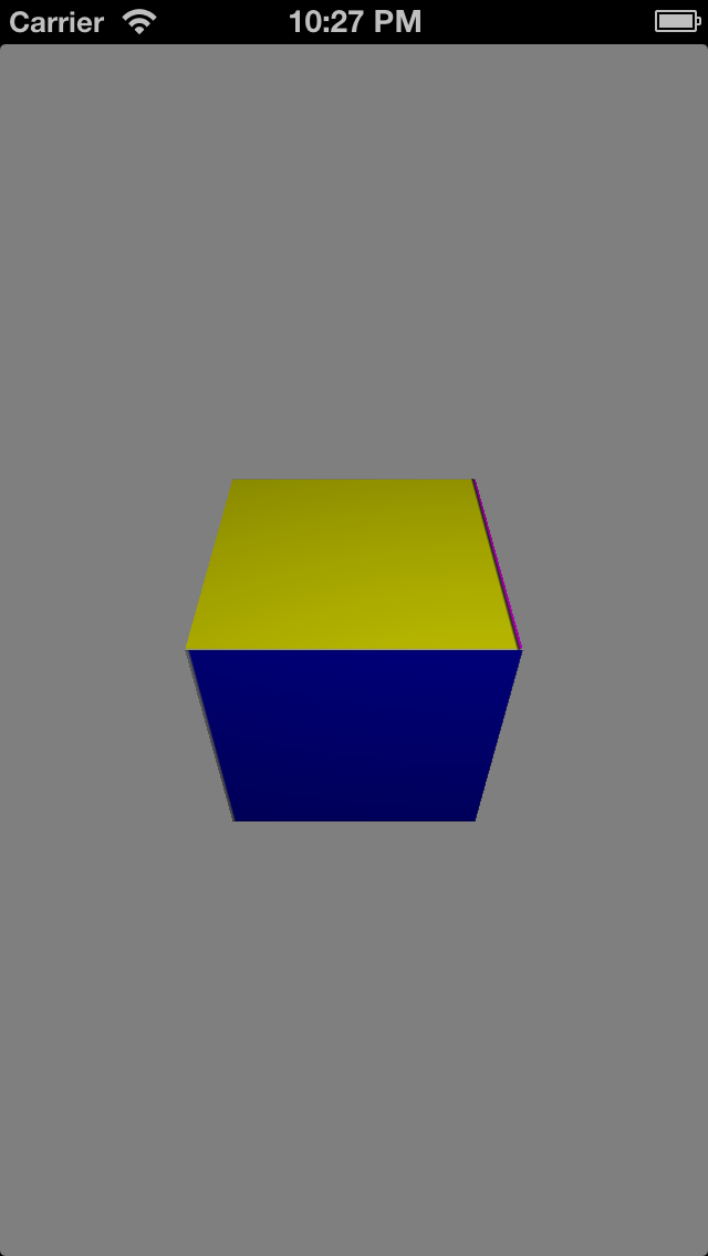
Build and run. Now you’ve got, um, something...

Believe it or not, this is your cube! Your geometry is in place, but it’s very difficult to appreciate it—so you should probably add at least a texture and some light to make it look nice. :]
Rendering Your Model: Texture
Add the following bit of code inside your createEffect function:
// Texture
NSDictionary* options = @{ GLKTextureLoaderOriginBottomLeft: @YES };
NSError* error;
NSString* path = [[NSBundle mainBundle] pathForResource:@"cube.png" ofType:nil];
GLKTextureInfo* texture = [GLKTextureLoader textureWithContentsOfFile:path options:options error:&error];

if(texture == nil)
    NSLog(@"Error loading file: %@", [error localizedDescription]);

self.effect.texture2d0.name = texture.name;
self.effect.texture2d0.enabled = true;
This is standard boilerplate code for a GLKTextureLoader, which simply attaches the cube.png texture to your effect. If you’re interested in the DVD extras, I suggest you read the official documentation.
Moving on, add the following lines to glkView:drawInrect:, just before your call to glDrawArrays():
// Texels
glEnableVertexAttribArray(GLKVertexAttribTexCoord0);
glVertexAttribPointer(GLKVertexAttribTexCoord0, 2, GL_FLOAT, GL_FALSE, 0, cubeTexels);
Similar to your cube’s positions, you provide an index for texture access data to OpenGL ES as a bound attribute array, in the form of two floats (UV) per vertex found in the sequential array cubeTexels[].
Build and run! Your cube should look much nicer now. :D

Rendering Your Model: Light
Add the following bit of code inside your createEffect function:
// Light
self.effect.light0.enabled = GL_TRUE;
self.effect.light0.position = GLKVector4Make(1.0f, 1.0f, 1.0f, 1.0f);
self.effect.lightingType = GLKLightingTypePerPixel;
This creates a single light source for your scene, coming from the top-right corner behind the viewer. The light uses per-pixel lighting, which you'll learn more about in Part 3 of this tutorial series.
Next, add the following lines to glkView:drawInrect:, also just before your call to glDrawArrays():
// Normals
glEnableVertexAttribArray(GLKVertexAttribNormal);
glVertexAttribPointer(GLKVertexAttribNormal, 3, GL_FLOAT, GL_FALSE, 0, cubeNormals);
As before, you provide an index of normal vectors to OpenGL ES as a bound attribute array, in the form of three floats (XYZ) per vertex found in the sequential array cubeNormals[].
Build and run! You should see much smoother shading now.
Rendering Your Model: Animation
Finally, you’ll add some basic animation to your cube to see all of its faces.
At the top of MainViewController.m, add the following variable inside the @interface extension:
float _rotate;
And initialize it inside viewDidLoad:
// Variables
_rotate = 0.0f;
Now add two more rotation commands to your ModelView matrix inside setMatrices, after you rotate the x-axis:
modelViewMatrix = GLKMatrix4RotateY(modelViewMatrix, GLKMathDegreesToRadians(_rotate));
modelViewMatrix = GLKMatrix4RotateZ(modelViewMatrix, GLKMathDegreesToRadians(_rotate));
And add the following function at the bottom of your file, just above the @end statement:
- (void)update
{
    _rotate += 1.0f;
}
This is a delegate method of GLKViewController that updates every frame, so you don’t need to call it from anywhere else—it’s automatically done for you.
Build and run—your animated cube is proudly showcased in your app, having made a long journey from Blender!

Where to Go From Here?

Here is the completed project with all of the code and resources from this part of the Blender to OpenGL ES tutorial. You can also find its repository on GitHub.
Congratulations, you’ve laid the foundations for a solid model viewer using a wide range of tools and technologies! This was quite a difficult and ambitious tutorial, so you should feel very proud of yourself.
You should now understand the geometry definitions of a simple 3D model and know how to analyze an OBJ file. You should be comfortable building a command line tool in Xcode and handling different types of files, too. You’ve barely touched the iOS side of things, but I hope you now appreciate how fast it is to get up and running with GLKit.
This tutorial hasn’t covered content creation with Blender, so be sure to check out our previous tutorialon that if you're feeling artistic.
In Part 2 of this tutorial series, you’ll be introduced to OBJ’s materialistic sibling: MTL. With this new file format, you’ll expand your command line tool to parse richer models and implement cool-looking materials! Basically, you’ll experience Part 1 on steroids. :O
Then you'll want to check out Part 3 of this tutorial.
If you have any questions, comments or suggestions, feel free to join the discussion below!


 被折叠的 条评论
为什么被折叠?
被折叠的 条评论
为什么被折叠?
 到【灌水乐园】发言


