


之前在STM32F103上移植过PMBus从机程序,这次要设计服务器数字电源,PMBus不可少。这次使用的是TI的TMS320F280049C系列,以TI的TIDA-010062设计参考为基础,结合技术手册熟悉相关外设的配置后(最主要就是EPWM、ADC及CMPSS模块),也趁硬件PCB还没有完成,PFC+LLC还不能调试,就开始验证PMBus这一块。正好手头上有一块之前学习BUCK数字电路购买的LAUNCHXL-F280049C Development Kit,就拿它做试验。我还是使用原来的TI参考样例,下载地址如下:
http://www.ti.com/lit/zip/SPRABJ6
我的测试项目截图如下:
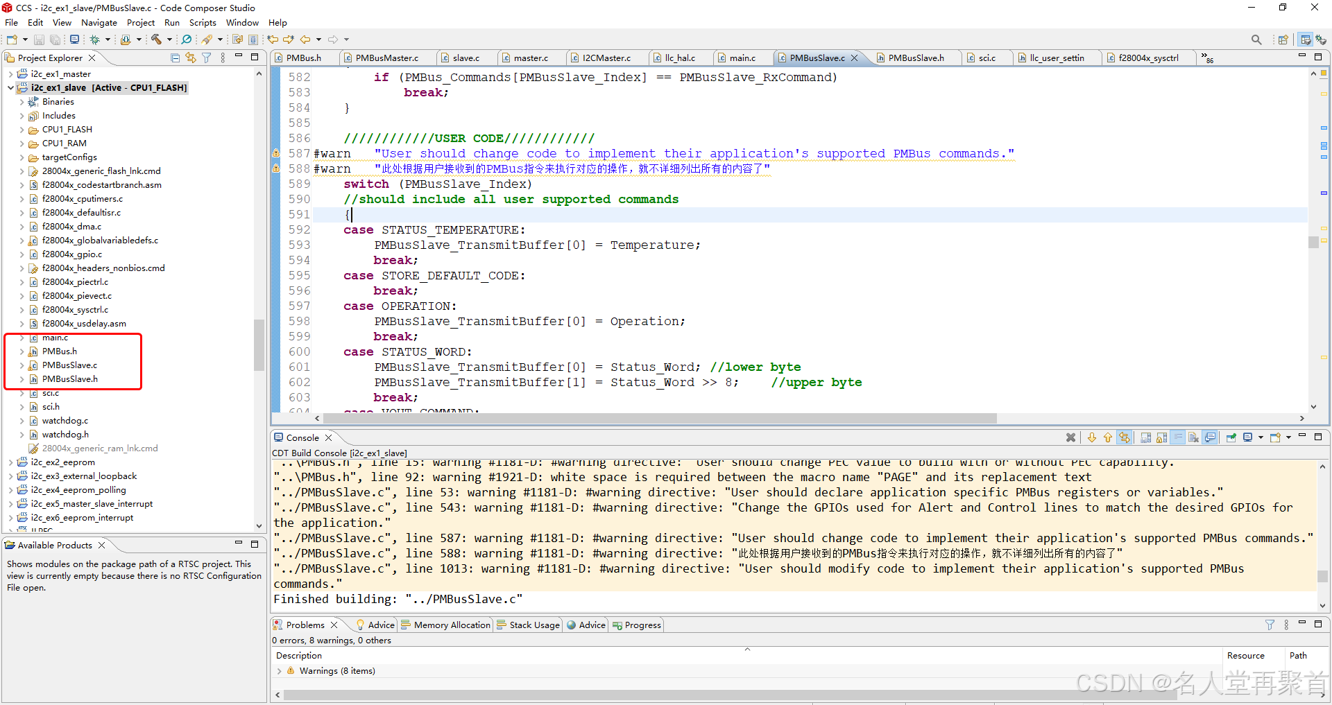
其中最主要是用到PMBusSlave.c,PMBusSlave.h,PMBus.h及main.c文件,主程序如下:
//#############################################################################
//
// FILE:   i2c_ex1_slave.c
//
// TITLE:  I2C Example Slave.
//
//! \addtogroup bitfield_example_list
//! <h1>I2C master slave communication using bit-field and without FIFO </h1>
//!
//! This program shows how to use I2CA in slave configuration.
//! This example uses I2C interrupts and doesn't use FIFO.
//!
//! \b Requires two Control Cards - one configured as Master and other as Slave \n
//! \b Master will run the binary generated from "i2c_ex1_master.projectspec" \n
//! \b Slave will run the binary generated from "i2c_ex1_slave.projectspec" \n
//! \b External \b Connections on Control Cards should be made as shown below \n
//!  --------------------------------------------------------------
//!    Signal   |  I2CA on Board1       |  I2CA on Board 2
//!  -----------------------------------------------------------------
//!     SCL     | GPIO_PIN_SCLA         |  GPIO_PIN_SCLA
//!     SDA     | GPIO_PIN_SDAA         |  GPIO_PIN_SDAA
//!     GND     |   GND                 |   GND
//!  ---------------------------------------------------------------
//!
//! \b Watch \b Variables in memory window\n
//!  - \b I2CA_TXdata
//!  - \b I2CA_RXdata
//!
//
//#############################################################################
// $Copyright:
// Copyright (C) 2024 Texas Instruments Incorporated - http://www.ti.com/
//
// Redistribution and use in source and binary forms, with or without
// modification, are permitted provided that the following conditions
// are met:
//
//   Redistributions of source code must retain the above copyright
//   notice, this list of conditions and the following disclaimer.
//
//   Redistributions in binary form must reproduce the above copyright
//   notice, this list of conditions and the following disclaimer in the
//   documentation and/or other materials provided with the
//   distribution.
//
//   Neither the name of Texas Instruments Incorporated nor the names of
//   its contributors may be used to endorse or promote products derived
//   from this software without specific prior written permission.
//
// THIS SOFTWARE IS PROVIDED BY THE COPYRIGHT HOLDERS AND CONTRIBUTORS
// "AS IS" AND ANY EXPRESS OR IMPLIED WARRANTIES, INCLUDING, BUT NOT
// LIMITED TO, THE IMPLIED WARRANTIES OF MERCHANTABILITY AND FITNESS FOR
// A PARTICULAR PURPOSE ARE DISCLAIMED. IN NO EVENT SHALL THE COPYRIGHT
// OWNER OR CONTRIBUTORS BE LIABLE FOR ANY DIRECT, INDIRECT, INCIDENTAL,
// SPECIAL, EXEMPLARY, OR CONSEQUENTIAL DAMAGES (INCLUDING, BUT NOT
// LIMITED TO, PROCUREMENT OF SUBSTITUTE GOODS OR SERVICES; LOSS OF USE,
// DATA, OR PROFITS; OR BUSINESS INTERRUPTION) HOWEVER CAUSED AND ON ANY
// THEORY OF LIABILITY, WHETHER IN CONTRACT, STRICT LIABILITY, OR TORT
// (INCLUDING NEGLIGENCE OR OTHERWISE) ARISING IN ANY WAY OUT OF THE USE
// OF THIS SOFTWARE, EVEN IF ADVISED OF THE POSSIBILITY OF SUCH DAMAGE.
// $
//#############################################################################

//
// Included Files
//
#include "f28x_project.h"
#include "PMBusSlave.h"
#include "sci.h"
#include "watchdog.h"

#define RUN_LED_GPIO                  23
#define RUN_LED_PIN_CONFIG            GPIO_23_GPIO23
#define RUN_LED_PRESCALE              ((uint16_t)5)

void HAL_setupRunLed(void)
{
    //
    // GPIO23 requires additional configuration on F28004x
    //
#if(RUN_LED_GPIO == 23)
    //GPIO_setAnalogMode(RUN_LED_GPIO, GPIO_ANALOG_DISABLED);
#endif
    //GPIO_setDirectionMode(RUN_LED_GPIO, GPIO_DIR_MODE_OUT);
    //GPIO_setPinConfig(RUN_LED_PIN_CONFIG);

    //GPIO_SetupPinMux(RUN_LED_GPIO, GPIO_MUX_CPU1, 0);
    //GPIO_SetupPinOptions(RUN_LED_GPIO, GPIO_PUSHPULL, GPIO_PULLUP);

    GPIO_SetupPinMux(RUN_LED_GPIO, GPIO_MUX_CPU1, 0);
    GPIO_SetupPinOptions(RUN_LED_GPIO, GPIO_OUTPUT, GPIO_PUSHPULL);
}

void LED_Run(void)
{
    GPIO_WritePin(RUN_LED_GPIO, 0);
    DELAY_US(500000);
    GPIO_WritePin(RUN_LED_GPIO, 1);
    DELAY_US(500000);
}

void main(void)
{
    //
    // Initialize System Control: PLL, WatchDog, enable Peripheral Clocks
    //
    InitSysCtrl();

    //
    // Initialize GPIO
    //
    InitGpio();

    //
    // Initialize the PIE control registers to their default state.
    // The default state is all PIE interrupts disabled and flags are cleared.
    //
    InitPieCtrl();

    //
    // Disable CPU interrupts and clear all CPU interrupt flags
    //
    IER = 0x0000;
    IFR = 0x0000;

    //
    // Initialize the PIE vector table with pointers to the shell Interrupt Service Routines (ISR)
    //
    InitPieVectTable();

    // Initialize I2C Module
    PMBusSlave_Init(I2C_SLAVE_ADDR);
    HAL_setupRunLed();
    Watchdog_Init();
    SCI_FIFO_Init();

    while (1)
    {
        PMBus_Error_Detect();
        ServiceDog();
        //SCI_Run();
    }
}
主要是LED配置(系统运行提示)、PMBus从机初始化,看门狗和SCI模块可忽略。主要看下PMBusSlave_Init函数的配置底层I2C驱动(TI原来提供的模板代码我没有注释,实际用到的GPIO分别是:SDA: GPIO35, SCL: GPIO37),PMBusSlave_Init函数和I2CSlave_Init函数代码分别如下:
PMBusSlave_Init函数:
/***************************************************************************//**
 * @brief   Configure the C2000 device as a PMBus slave.
 * @param   PMBusSlave_DeviceAddress The slave device's own address.
 * @return  None
 ******************************************************************************/
#warn "Change the GPIOs used for Alert and Control lines to match the desired GPIOs for the application."
void PMBusSlave_Init(unsigned char PMBusSlave_DeviceAddress)
{
//GPIO配置我保持了原来的,没有注释,但实际上用的的GPIO35和GPIO37
    StatusRegs.StatusWord.all = 0; //Clear status bits for the status registers we are using
    StatusRegs.StatusCml.all = 0;

    // Control Line functionality GPIO0
    GpioCtrlRegs.GPAPUD.bit.GPIO0 = 0;		//Enable pullup on GPIO0
    GpioDataRegs.GPASET.bit.GPIO0 = 1;		//Drive line high
    GpioCtrlRegs.GPAQSEL1.bit.GPIO0 = 0;	//SYNC to SYSCLKOUT
    GpioCtrlRegs.GPACTRL.bit.QUALPRD0 = 0;//no qualification (SYNC to SYSCLKOUT)
    GpioCtrlRegs.GPAMUX1.bit.GPIO0 = 0;		//GPIO0 = GPIO0
    GpioCtrlRegs.GPADIR.bit.GPIO0 = 0;		//GPIO0 = input

    // SMBUS Alert functionality (GPIO2 = Alert line)
    GpioCtrlRegs.GPAPUD.bit.GPIO2 = 0;		//Enable pullup on GPIO2
    GpioDataRegs.GPASET.bit.GPIO2 = 1;		//Drive line high
    GpioCtrlRegs.GPAMUX1.bit.GPIO2 = 0;		//GPIO2 = GPIO2
    GpioCtrlRegs.GPADIR.bit.GPIO2 = 1;		//GPIO2 = output

    slave_address = PMBusSlave_DeviceAddress;
    I2CSlave_Init(slave_address);     // Initialize USCI module
}
I2CSlave_Init函数:
该函数配置内容如下:
1、I2C用到的GPIO即SDA和SCL;
2、timer0和timer1的配置及对应的ISR;
3、I2C的中断配置及对应的ISR;
TI示例中原来的方案是采用轮询的方式来运行PMBus协议,也就是在主循环中调用PMBusSlave函数,这里我使用的是中断方式,每次产生I2C中断时就调用StartCpuTimer0函数启动timer0,如果数据正确则调用StopCpuTimer0函数关闭timer0,否则执行超时机制,一般是重置I2C模块。
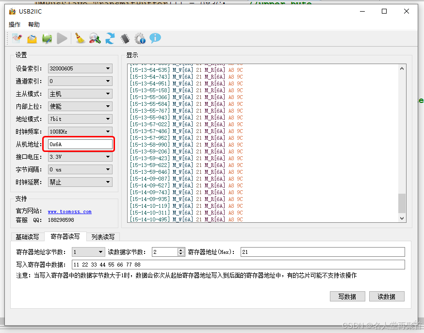
timer1用于1毫秒定时,产生LED灯闪烁,另外用于监测I2C从机的状态,特别是SDA信号被长时间拉低导致总线卡死,这时就需要重置I2C,监测的函数是PMBus_Error_Detect,在主循环中调用。实际调试我使用TOOMOSS的USB转I2C设备,故意使用错误的数据长度,不按PMBus规范发送数据,确实会产生这种错误,即使没有产生错误,或者通过I2C主机也可以解决I2C死锁问题,但是为了程序的健壮和可靠,也需要做一些预防措施确保总线的稳定。
图1显示了在TOOMOSS设备中的测试画面,以0x21指令为例,测试结果收到的数据和图2中的RWWORD命令组发送的数据一致:
图1:
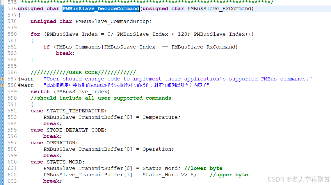
在I2C的中断处理函数__interrupt void I2CISR(void)中,我增加了一个函数i2c_sent_timeout,用于发送超时处理,实际运行时发现在执行RWWORD指令时while(I2caRegs.I2CSTR.bit.BYTESENT != 0x1)有时出现死循环,因此增加了超时处理机制。测试中我使用的是自定义数据,当然用户可根据实际应用结合PMBus协议在函数PMBusSlave_DecodeCommand中设置PMBusSlave_TransmitBuffer数组成员值,如图2和图3所示:
/***************************************************************************//**
 * @brief   Initialize I2C module in slave mode.
 * @param   I2CSlave_OwnAddress The slave device's own address.
 * @return  None
 ******************************************************************************/
void I2CSlave_Init(Uint16 I2CSlave_OwnAddress)
{
    GPIO_SetupPinMux(GPIO_PIN_SDAA, GPIO_MUX_CPU1, 3); //Technical reference manual of page 45 for the alternate function of GPIO35 and GPIO37
    GPIO_SetupPinOptions(GPIO_PIN_SDAA, GPIO_OUTPUT, GPIO_PULLUP);
    GPIO_SetupPinMux(GPIO_PIN_SCLA, GPIO_MUX_CPU1, 3);
    GPIO_SetupPinOptions(GPIO_PIN_SCLA, GPIO_OUTPUT, GPIO_PULLUP);

    //Setup CPU Timer 0 interrupt
    EALLOW;	            // This is needed to write to EALLOW protected registers
    PieVectTable.TIMER0_INT = &cpu_timer0_isr;
    PieVectTable.TIMER1_INT = &cpu_timer1_isr;
    EDIS;       // This is needed to disable write to EALLOW protected registers

    // Enable TINT0 in the PIE: Group 1 interrupt 7, 请参考技术手册第90页表格的第一行
    PieCtrlRegs.PIEIER1.bit.INTx7 = 1;

    //PieCtrlRegs.PIEIER1.bit.INTx13 = 1;
    //Interrupt_enable(INT_TIMER1);
    CpuTimer0Regs.TCR.all = 0x4000;
    CpuTimer1Regs.TCR.all = 0x4000;

    //
    // Enable CPU int1 which is connected to CPU-Timer 0
    // CPU int13: which is connected to CPU-Timer 1
    // CPU int14: which is connected to CPU-Timer 2
    //
    IER |= M_INT1;
    IER |= M_INT13;    //Timer1 interrupt is enabled
    //IER |= M_INT14;

    InitCpuTimers();
    ConfigCpuTimer(&CpuTimer0, 60, 35000); //CPU Timer 0 interrupt after 35 ms (at 60MHz CPU freq.)
    ConfigCpuTimer(&CpuTimer1, 100, 1000); //CPU Timer 1 interrupt after 1 ms (at 100MHz CPU freq.)

    //
    // Register the interrupt ISR for I2C interface
    //
    EALLOW;             // This is needed to write to EALLOW protected registers
    PieVectTable.I2CA_INT = &I2CISR;
    EDIS;       // This is needed to disable write to EALLOW protected registers

    //
    // Enable Interrupts
    //
    PieCtrlRegs.PIEIER8.bit.INTx1 = 0x1; // Enable PIE Group 8 INT8,I2CA的中断允许位,请参考技术手册第90页表格中的INT8.y
    IER |= M_INT8;                          // Enable CPU INT8
    EINT;
    // Enable Global Interrupts
    ERTM;
    EnableInterrupts();
    EALLOW;
    I2caRegs.I2CMDR.all &= ~(0x20U);        // Reset the I2C Module
    I2caRegs.I2CMDR.bit.MST = 0x0U;    // Configure I2C as slave in Receive mode
    I2caRegs.I2CMDR.bit.TRX = 0x0U;
    I2caRegs.I2CMDR.bit.BC = 0x0U;  // Set the bit count to 8 bits per data byte
    I2caRegs.I2CMDR.bit.FREE = 0x1;         // Set emulation mode to FREE
    I2caRegs.I2COAR.all = I2CSlave_OwnAddress; // Configure I2C own address
    I2caRegs.I2CSTR.all = 0xFFFF;           //Clear all status
    I2caRegs.I2CIER.all = 0x78; // Enable I2C Interrupts- AAS, STOP, XRDY and RRDY
    I2caRegs.I2CMDR.all |= 0x0020;          // Take I2C out of reset
    EDIS;

    //Initialize I2C
    //I2caRegs.I2COAR.all = I2CSlave_OwnAddress;		// Own address
    //I2caRegs.I2CPSC.all = 9;		                    // Prescaler - need 7-12 Mhz on module clk
    //I2caRegs.I2CCLKL = 10;			                // NOTE: must be non zero
    //I2caRegs.I2CCLKH = 5;			                    // NOTE: must be non zero
    //I2caRegs.I2CIER.all = 0x00;		                // Clear interrupts - polling based method
    //I2caRegs.I2CMDR.all = 0x0020;	                    // Take I2C out of reset
    // Stop I2C when suspended
    StartCpuTimer1();

    return;
}
图2:发送的示例数据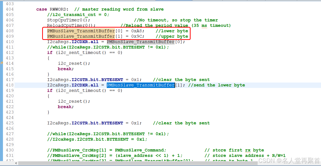
图3:在函数PMBusSlave_DecodeCommand中根据指令设置要发送的数据
这次的PMBus从机程序我没有使用PEC,这个只是数据包装和解析不同,其他的都是一样的,在此就不多说,完整工程可以从以下链接下载(不需要积分):
【免费】TMS320F280049CPMBus从机实现资源-CSDN文库
使用的软件版本信息如下:
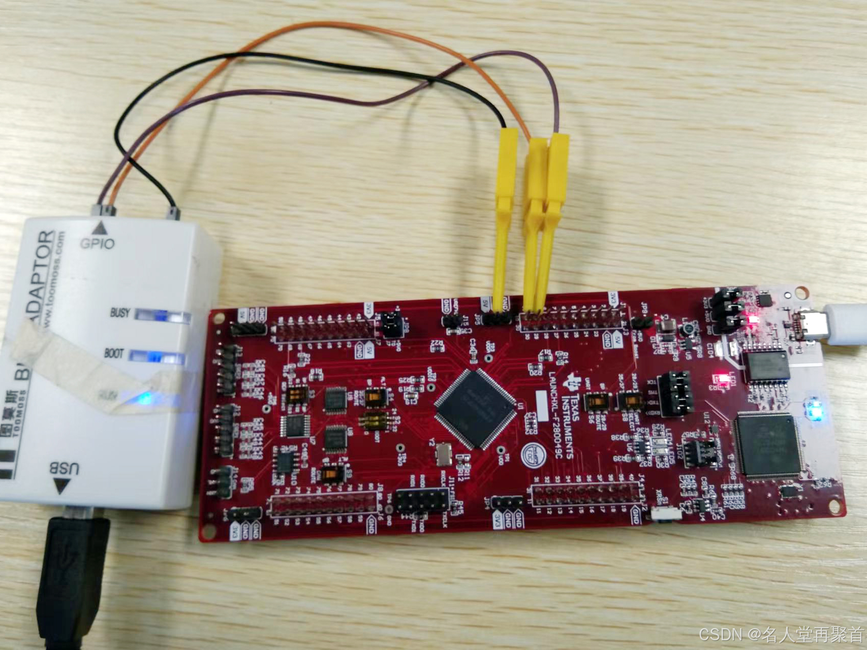
实验的硬件连接如下图所示:


 1万+
1万+

 被折叠的 条评论
为什么被折叠?
被折叠的 条评论
为什么被折叠?
 到【灌水乐园】发言


