


USB Basics
From http://www.usb.org
4.1.1 Bus Topology
The USB physical interconnect is a tiered star topology.
the maximum number of tiers allowed is seven (including the root tier).
4.1.1.2 USB Devices
USB devices are one of the following:
• Hubs, which provide additional attachment points to the USB
• Functions, which provide capabilities to the system, such as an ISDN connection, a digital joystick, or speakers
4.3.1 Power Distribution
any USB device may have its own power supply.
USB devices that rely totally on power from the cable are called bus-powered devices.
In contrast, those that have an alternate source of power are called self-powered devices
4.4 Bus Protocol
The USB is a polled bus. The Host Controller initiates all data transfers.
Most bus transactions involve the transmission of up to three packets. Each transaction begins when the Host Controller, on a scheduled basis, sends a USB packet describing the type and direction of transaction, the USB device address, and endpoint number. This packet is referred to as the “token packet.” The USB device that is addressed selects itself by decoding the appropriate address fields. In a given transaction, data is transferred either from the host to a device or from a device to the host. The direction of data transfer is specified in the token packet. The source of the transaction then sends a data packet or indicates it has no data to transfer. The destination, in general, responds with a handshake packet indicating whether the transfer was successful.
Some bus transactions between host controllers and hubs involve the transmission of four packets. These types of transactions are used to manage the data transfers between the host and full-/low- speed devices.
The USB data transfer model between a source or destination on the host and an endpoint on a device is referred to as a pipe. There are two types of pipes: stream and message. Stream data has no USB-defined structure, while message data does. Additionally, pipes have associations of data bandwidth, transfer service type, and endpoint characteristics like directionality and buffer sizes. Most pipes come into
existence when a USB device is configured. One message pipe, the Default Control Pipe, always exists once a device is powered, in order to provide access to the device’s configuration, status, and control information.
The transaction schedule allows flow control for some stream pipes. At the hardware level, this prevents buffers from underrun or overrun situations by using a NAK handshake to throttle the data rate. When NAKed, a transaction is retried when bus time is available. The flow control mechanism permits the construction of flexible schedules that accommodate concurrent servicing of a heterogeneous mix of stream pipes. Thus, multiple stream pipes can be serviced at different intervals and with packets of different sizes.
4.6.1 Attachment of USB Devices
All USB devices attach to the USB through ports on specialized USB devices known as hubs. Hubs have status bits that are used to report the attachment or removal of a USB device on one of its ports. The host queries the hub to retrieve these bits. In the case of an attachment, the host enables the port and addresses the USB device through the device抯 control pipe at the default address. The host assigns a unique USB address to the device and then determines if the newly attached USB device is a hub or a function. The host establishes its end of the control pipe for the USB device using the assigned USB address and endpoint number zero.
If the attached USB device is a hub and USB devices are attached to its ports, then the above procedure is followed for each of the attached USB devices.
If the attached USB device is a function, then attachment notifications will be handled by host software that is appropriate for the function.
4.6.2 Removal of USB Devices
When a USB device has been removed from one of a hub’s ports, the hub disables the port and provides an indication of device removal to the host. The removal indication is then handled by appropriate USB System Software. If the removed USB device is a hub, the USB System Software must handle the removal of both the hub and of all of the USB devices that were previously attached to the system through the hub.
4.6.3 Bus Enumeration
Bus enumeration is the activity that identifies and assigns unique addresses to devices attached to a bus. Because the USB allows USB devices to attach to or detach from the USB at any time, bus enumeration is an on-going activity for the USB System Software. Additionally, bus enumeration for the USB also includes the detection and processing of removals.
4.7 Data Flow Types
The USB supports functional data and control exchange between the USB host and a USB device as a set of either uni-directional or bi-directional pipes. USB data transfers take place between host software and a particular endpoint on a USB device. Such associations between the host software and a USB device endpoint are called pipes. In general, data movement though one pipe is independent from the data flow in any other pipe. A given USB device may have many pipes. As an example, a given USB device could have an endpoint that supports a pipe for transporting data to the USB device and another endpoint that supports a pipe for transporting data from the USB device.
The USB architecture comprehends four basic types of data transfers:
?Control Transfers: Used to configure a device at attach time and can be used for other device-specific purposes, including control of other pipes on the device.
?Bulk Data Transfers: Generated or consumed in relatively large and bursty quantities and have wide dynamic latitude in transmission constraints.Reliable exchange of data is ensured at the hardware level by using error detection in hardware and invoking a limited number of retries in hardware
?Interrupt Data Transfers: Used for timely but reliable delivery of data, for example, characters or coordinates with human-perceptible echo or feedback response characteristics.
?Isochronous Data Transfers: Occupy a prenegotiated amount of USB bandwidth with a prenegotiated delivery latency. (Also called streaming real time transfers).
A pipe supports only one of the types of transfers described above for any given device configuration.
4.8 USB Devices
USB devices are divided into device classes such as hub, human interface, printer, imaging, or mass storage device. The hub device class indicates a specially designated USB device that provides additional USB attachment points (refer to Chapter 11). USB devices are required to carry information for selfidentification and generic configuration. They are also required at all times to display behavior consistent with defined USB device states.
4.8.1 Device Characterizations
All USB devices are accessed by a USB address that is assigned when the device is attached and enumerated. Each USB device additionally supports one or more pipes through which the host may communicate with the device. All USB devices must support a specially designated pipe at endpoint zero to which the USB device’s USB control pipe will be attached. All USB devices support a common access mechanism for accessing information through this control pipe.
Associated with the control pipe at endpoint zero is the information required to completely describe the USB device. This information falls into the following categories:
• Standard: This is information whose definition is common to all USB devices and includes items such as vendor identification, device class, and power management capability. Device, configuration, interface, and endpoint descriptions carry configuration-related information about the device. Detailed information about these descriptors can be found in Chapter 9.
• Class: The definition of this information varies, depending on the device class of the USB device.
• USB Vendor: The vendor of the USB device is free to put any information desired here. The format, however, is not determined by this specification.
Additionally, each USB device carries USB control and status information.
4.8.2.1 Hubs
Hubs are wiring concentrators and enable the multiple attachment characteristics of the USB. Attachment points are referred to as ports. Each hub converts a single attachment point into multiple attachment points. The architecture supports concatenation of multiple hubs.
4.8.2.2 Functions
A function is a USB device that is able to transmit or receive data or control information over the bus. A function is typically implemented as a separate peripheral device with a cable that plugs into a port on a hub. Each function contains configuration information that describes its capabilities and resource requirements.
Before a function can be used, it must be configured by the host. This configuration includes allocating USB bandwidth and selecting function-specific configuration options.
5.3.1 Device Endpoints
An endpoint is a uniquely identifiable portion of a USB device that is the terminus of a communication flow between the host and device. Each USB logical device is composed of a collection of independent endpoints. Each logical device has a unique address assigned by the system at device attachment time.
5.3.2 Pipes
A USB pipe is an association between an endpoint on a device and software on the host. Pipes represent the ability to move data between software on the host via a memory buffer and an endpoint on a device. There are two mutually exclusive pipe communication modes:
• Stream: Data moving through a pipe has no USB-defined structure
• Message: Data moving through a pipe has some USB-defined structure
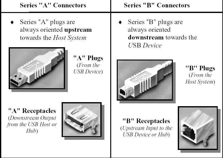
6.2 Keyed Connector Protocol
. Series “A” receptacle mates with a Series “A” plug. Electrically, Series “A” receptacles function as outputs from host systems and/or hubs.
. Series “A” plug mates with a Series “A” receptacle. The Series “A” plug always is oriented towards the host system.
. Series “B” receptacle mates with a Series “B” plug (male). Electrically, Series “B” receptacles function as inputs to hubs or devices.
. Series “B” plug mates with a Series “B” receptacle. The Series “B” plug is always oriented towards the USB hub or device.
7.1.5.1 Low-/Full-speed Device Speed Identification
The USB is terminated at the hub and function ends as shown in Figure 7-20 and Figure 7-21. Full-speed and
low-speed devices are differentiated by the position of the pull-up resistor on the downstream end of the cable:
. Full-speed devices are terminated as shown in Figure 7-20 with the pull-up resistor on the D+ line.
. Low-speed devices are terminated as shown in Figure 7-21 with the pull-up resistor on the D- line.
. The pull-down terminators on downstream facing ports are resistors of 15 kΩ ±5% connected to ground.
7.1.5.2 High-speed Device Speed Identification
High-speed capable devices initially attach as full-speed devices. This means that for high-speed capable upstream facing ports, RPU (1.5 kΩ ±5%) must be connected from D+ to the 3.3 V supply (as shown in Figure 7-1) through a switch which can be opened under SW control.
After the initial attachment, high-speed capable transceivers engage in a low level protocol during reset to establish a high-speed link and to indicate high-speed operation in the appropriate port status register. This protocol is described in Section 7.1.7.5.
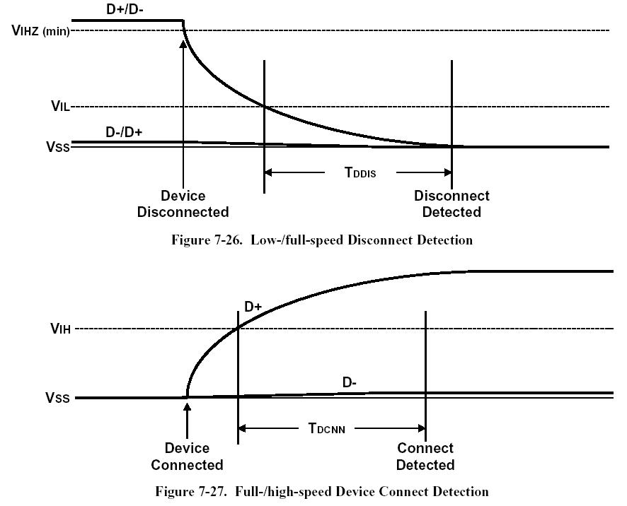
7.1.7.3 Connect and Disconnect Signaling
When no function is attached to the downstream facing port of a host or hub in low-/full-speed, the pull-down resistors present there will cause both D+ and D- to be pulled below the single-ended low threshold of the host or hub transceiver when that port is not being driven by the hub. This creates an SE0 state on the downstream facing port. A disconnect condition is indicated if the host or hub is not driving the data lines and an SE0 persists on a downstream facing port for more than TDDIS (see Figure 7-26). The specifications for TDDIS and TDCNN are defined in Table 7-13.
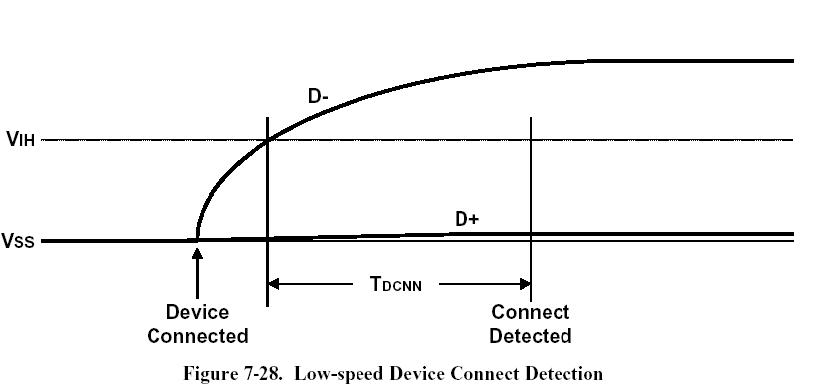
A connect condition will be detected when the hub detects that one of the data lines is pulled above its VIH threshold for more than TDCNN (see Figure 7-27 and Figure 7-28).
Hubs must determine the speed of the attached device by sampling the state of the bus immediately before driving SE0 to indicate a reset condition to the device.
All signaling levels given in Table 7-2 are set for this bus segment (and this segment alone) once the speed of the attached device is determined. The mechanics of speed detection are described in Section 11.8.2.
7.1.8 Data Encoding/Decoding
The USB employs NRZI data encoding when transmitting packets. In NRZI encoding, a “1” is represented by no change in level and a “0” is represented by a change in level. Figure 7-31 shows a data stream and the NRZI equivalent. The high level represents the J state on the data lines in this and subsequent figures showing NRZI encoding. A string of zeros causes the NRZI data to toggle each bit time. A string of ones causes long periods with no transitions in the data.
7.1.9 Bit Stuffing
In order to ensure adequate signal transitions, bit stuffing is employed by the transmitting device when sending a packet on USB (see Figure 7-32 and Figure 7-34). A zero is inserted after every six consecutive ones in the data stream before the data is NRZI encoded, to force a transition in the NRZI data stream.
8.1 Byte/Bit Ordering
Bits are sent out onto the bus least-significant bit (LSb) first, followed by the next LSb, through to the mostsignificant bit (MSb) last.
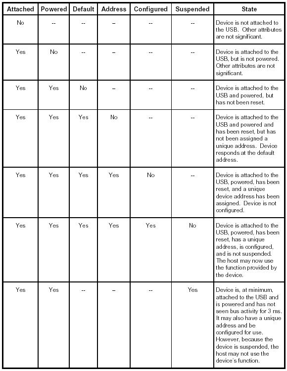
9.1.1 Visible Device States
 9
9
9.1.2 Bus Enumeration
When a USB device is attached to or removed from the USB, the host uses a process known as bus enumeration to identify and manage the device state changes necessary. When a USB device is attached to a powered port, the following actions are taken:
1. The hub to which the USB device is now attached informs the host of the event via a reply on its status change pipe (refer to Section 11.12.3 for more information). At this point, the USB device is in the Powered state and the port to which it is attached is disabled.
2. The host determines the exact nature of the change by querying the hub.
3. Now that the host knows the port to which the new device has been attached, the host then waits for at least 100 ms to allow completion of an insertion process and for power at the device to become stable.
The host then issues a port enable and reset command to that port. Refer to Section 7.1.7.5 for sequence of events and timings of connection through device reset.
4. The hub performs the required reset processing for that port (see Section 11.5.1.5). When the reset signal is released, the port has been enabled. The USB device is now in the Default state and can draw no more than 100 mA from VBUS. All of its registers and state have been reset and it answers to the default address.
5. The host assigns a unique address to the USB device, moving the device to the Address state.
6. Before the USB device receives a unique address, its Default Control Pipe is still accessible via the default address. The host reads the device descriptor to determine what actual maximum data payload size this USB device’s default pipe can use.
7. The host reads the configuration information from the device by reading each configuration zero to n-1, where n is the number of configurations. This process may take several milliseconds to complete.
8. Based on the configuration information and how the USB device will be used, the host assigns a configuration value to the device. The device is now in the Configured state and all of the endpoints in this configuration have taken on their described characteristics. The USB device may now draw the amount of VBUS power described in its descriptor for the selected configuration. From the device’s point of view, it is now ready for use.
When the USB device is removed, the hub again sends a notification to the host. Detaching a device disables the port to which it had been attached. Upon receiving the detach notification, the host will update its local topological information.


 2776
2776

 被折叠的 条评论
为什么被折叠?
被折叠的 条评论
为什么被折叠?
 到【灌水乐园】发言


