


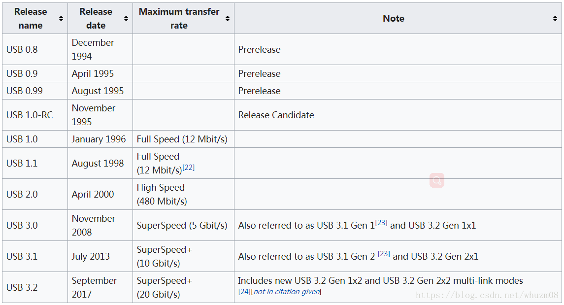
History
USB, short for Universal Serial Bus, A group of seven companies began the development of USB in 1994: Compaq, DEC, IBM, Intel, Microsoft, NEC, and Nortel.[7] The goal was to make it fundamentally easier to connect external devices to PCs by replacing the multitude of connectors at the back of PCs.
Limitations
USB cables are limited in length, as the standard was meant to connect to peripherals on the same table-top, not between rooms or between buildings.
USB has a strict "tree" topology and "master-slave" protocol for addressing peripheral devices; peripheral devices cannot interact with one another except via the host, and two hosts cannot communicate over their USB ports directly. A host cannot "broadcast" signals to all peripherals at once, each must be addressed individually.
The USB 1.1 standard specifies that a standard cable can have a maximum length of
5 metres
(16 ft 5 in) with devices operating at full speed (12 Mbit/s), and a maximum length of
3 metres
(9 ft 10 in) with devices operating at low speed (1.5 Mbit/s).
USB 2.0 provides for a maximum cable length of
5 metres
(16 ft 5 in) for devices running at high speed (480 Mbit/s).
The USB 3.0 standard does not directly specify a maximum cable length, requiring only that all cables meet an electrical specification: for copper cabling with
AWG
26 wires the maximum practical length is
3 meters
(9.8 ft)
Pinouts
USB 2.0
uses two wires for power (V
BUS
and GND), and two for
differential serial data signals(4根线:V+,D-,D+,GND)
. Mini and micro connectors have their GND connections moved from pin #4 to pin #5, while their pin #4 serves as an ID pin for the On-The-Go host/client identification(5根线:V+,D-,D+,ID,GND).
USB 3.0
provides two additional differential pairs (four wires, SSTx+, SSTx−, SSRx+ and SSRx−), providing
full-duplex
data transfers at
SuperSpeed
, which makes it similar to
Serial ATA
or single-lane
PCI Express
.
(9根线:V+,D-,D+,ID,GND,SSTx+, SSTx−, SSRx+,SSRx−,通过观察USB接口可以知道是否为USB3.0的,前面有4个触角,跟USB2.0一样,但是USB3.0后面隐藏着另一排5个触角)
The cable also carries VBUS and GND wires on each segment to deliver power to devices. VBUS is nominally +5 V at the source.
System design
A USB system consists of a host with one or more downstream ports, and multiple peripherals, forming a tiered-
star topology
.
A USB host may have multiple controllers, each with one or more ports. Up to 127 devices may be connected to a single host controller.
[38]
[39]
USB devices are linked in series through hubs. The hub built into the host controller is the root hub.
A USB device may consist of several logical sub-devices that are referred to as
device functions
.
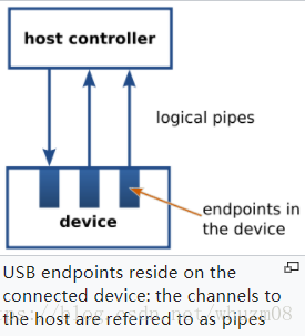
USB device communication is based on pipes (logical channels). A pipe is a connection from the host controller to a logical entity, found on a device, and named an endpoint.
Because pipes correspond to endpoints, the terms are sometimes used interchangeably.
A USB device could have up to 32 endpoints (16 IN, 16 OUT)
, though it is rare to have so many. An endpoint is defined and numbered by the device during initialization (the period after physical connection called "enumeration") and so is relatively permanent, whereas a pipe may be opened and closed.
There are two types of pipe: stream and message
. A message pipe is bi-directional and is used for
control
transfers. Message pipes are typically used for short, simple commands to the device, and a status response, used, for example, by the bus control pipe number 0. A stream pipe is a uni-directional pipe connected to a uni-directional endpoint that transfers data using an
isochronous
,
[40]
interrupt
, or
bulk
transfer
Due to timing constraints allowed for hub and cable propagation times, the maximum number of tiers allowed is seven (including the root tier).
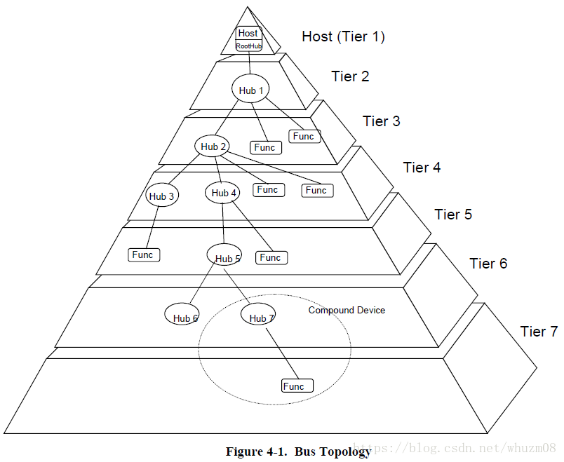
A root hub is integrated within the host system to provide one or more attachment points
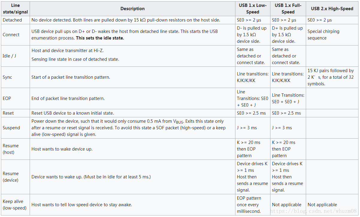
Signaling state
The host includes
15 kΩ pull-down resistors
on each data line. When no device is connected, this pulls both data lines low into the so-called
single-ended zero
state (SE0 in the USB documentation), and indicates a reset or disconnected connection.
Line transition state
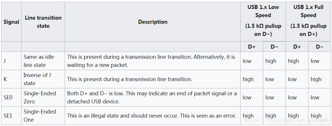
A USB device, pulls one of the data lines (D+ or D-)high with a 1.5 kΩ resistor , is connected to the host, This overpowers one of the pull-down resistors in the host and leaves the data lines in an idle state called J. (idle状态与J状态相同)
Line state (covering USB 1.x and 2.x)
Transmission
USB data is transmitted by toggling the data lines between the J state and the opposite K state. USB encodes data using the
NRZI
line coding
:
- 0 bit is transmitted by toggling the data lines from J to K or vice versa.
- 1 bit is transmitted by leaving the data lines as-is.
To ensure that there are enough signal transitions for clock recovery to occur in the
bitstream
, a
bit stuffing
technique is applied to the data stream: an extra 0 bit is insert into the data stream after any occurrence of six consecutive 1 bits. (Thus ensuring that there is a 0 bit to cause a transmission state transition.) Seven consecutively received 1 bits are always an error.
时钟信号是从J,K状态转换中恢复出来的,因为sync始终是以KJKJ串开始的,其目的就是为了恢复始终,所以不同的设备可以支持不同的速率,这也是为何USB3.0 sync需要更长的KJKJ串,因为USB3.0速率更快,需要恢复的时钟更精准。
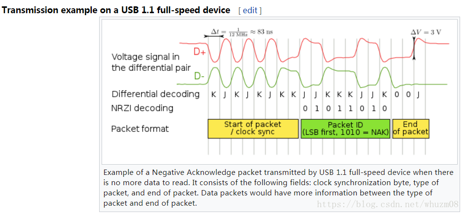
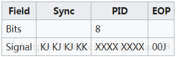
- Synchronization Pattern: A USB packet begins with an 8-bit synchronization sequence, 00000001₂. That is, after the initial idle state J, the data lines toggle KJKJKJKK. The final 1 bit (repeated K state) marks the end of the sync pattern and the beginning of the USB frame. For high-bandwidth USB, the packet begins with a 32-bit synchronization sequence.
- End of Packet (EOP): EOP is indicated by the transmitter driving 2 bit times of SE0 (D+ and D− both below max.) and 1 bit time of J state. After this, the transmitter ceases to drive the D+/D− lines and the aforementioned pull-up resistors hold it in the J (idle) state. Sometimes skew due to hubs can add as much as one bit time before the SE0 of the end of packet. This extra bit can also result in a "bit stuff violation" if the six bits before it in the CRC are 1s. This bit should be ignored by receiver.
- Bus Reset: A USB bus is reset using a prolonged (10 to 20 milliseconds) SE0 signal.
USB 2.0 speed negotiation(速度协商)
USB 2.0 devices use a special protocol during reset, called
chirping(嘀咕)
, to negotiate the high bandwidth mode with the host/hub. A device that is USB 2.0 High Speed capable first connects as a Full Speed device (D+ pulled high), but upon receiving a USB RESET (both D+ and D− driven LOW by host for 10 to 20 ms) it pulls the D− line high, known as chirp K. This indicates to the host that the device is high bandwidth. If the host/hub is also HS capable, it chirps (returns alternating J and K states on D− and D+ lines) letting the device know that the hub operates at high bandwidth. The device has to receive at least three sets of KJ chirps before it changes to high bandwidth terminations and begins high bandwidth signaling.
Protocol layer
The USB is a polled bus. The Host Controller initiates all data transfers.
During USB communication, data is transmitted as packets. Initially, all packets are sent from the host via the root hub, and possibly more hubs, to devices.
Some of those packets direct a device to send some packets in reply.
Most bus transactions involve the transmission of up to three packets. Each transaction begins when the
Host Controller, on a scheduled basis, sends a USB packet describing the type and direction of transaction,
the USB device address, and endpoint number. This packet is referred to as the “token packet.” The USB
device that is addressed selects itself by decoding the appropriate address fields. In a given transaction, data
is transferred either from the host to a device or from a device to the host. The direction of data transfer is
specified in the token packet. The source of the transaction then sends a data packet or indicates it has no
data to transfer. The destination, in general, responds with a handshake packet indicating whether the
transfer was successful.
After the sync field, all packets are made of 8-bit bytes, transmitted least-significant bit first. The first byte is a packet identifier (PID) byte. The PID is actually 4 bits; the byte consists of the 4-bit PID followed by its bitwise complement
. This redundancy helps detect errors. (Note also that a PID byte contains at most four consecutive 1 bits, and thus never needs
bit-stuffing
, even when combined with the final 1 bit in the sync byte. However, trailing 1 bits in the PID may require bit-stuffing within the first few bits of the payload.)
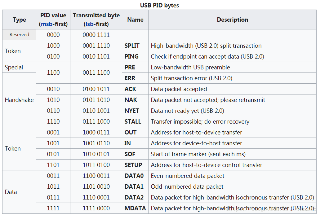
Handshake packets
Handshake packets consist of only a single PID byte, and are generally sent in response to data packets. Error detection is provided by transmitting four bits, which represent the packet type twice, in a single PID byte using
complemented
form.
ACK
, indicating that data was successfully received;
NAK
, indicating that the data cannot be received and should be retried;
STALL
, indicating that the device has an error condition and cannot transfer data until some corrective action (such as device initialization) occurs.
USB 2.0 added two additional handshake packets:
NYET,
indicates that a split transaction is not yet complete,or tell the host that the device has accepted a data packet, but cannot accept any more due to full buffers.
ERR
, indicates that a split transaction failed.
The only handshake packet the USB host may generate is ACK. If it is not ready to receive data, it should not instruct a device to send.
Token packets
Token packets consist of a PID byte followed by two payload bytes:
11 bits of address and a five-bit CRC
.
Tokens are only sent by the host, never a device.
- IN and OUT tokens contain a seven-bit device number and four-bit function number (for multifunction devices) and command the device to transmit DATAx packets, or receive the following DATAx packets, respectively.
Upon reset and power-up, a function’s address defaults to a value of zero and must be programmed by the host
during the enumeration process. Function address zero is reserved as the default address and may not be
assigned to any other use.
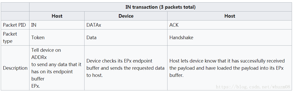
- IN token expects a response from a device. The response may be a NAK or STALL response or a DATAx frame. In the latter case, the host issues an ACK handshake if appropriate.
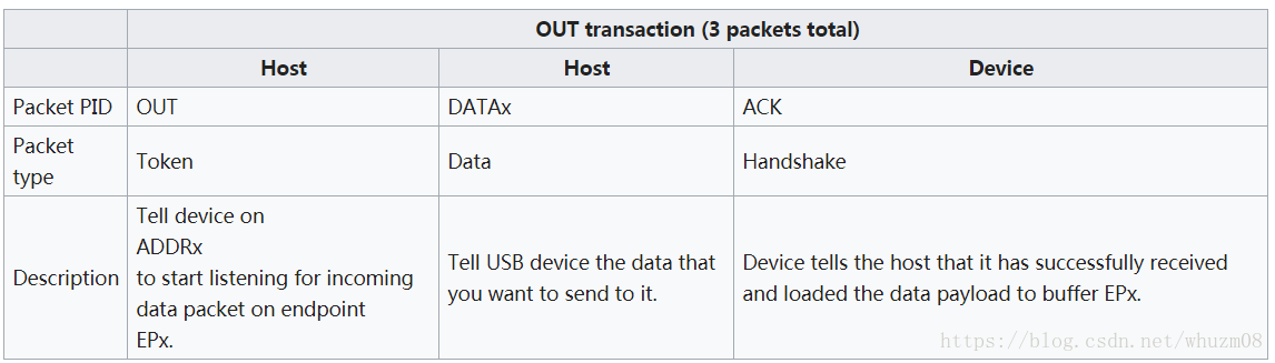
- OUT token is followed immediately by a DATAx frame. The device responds with ACK, NAK, NYET, or STALL, as appropriate.
- USB 2.0 also added a PING Token and a larger three-byte SPLIT Token
- PING asks a device if it is ready to receive an OUT/DATA packet pair. PING is usually sent by a host when polling a device that most recently responded with NAK or NYET. This avoids the need to send a large data packet to a device that the host suspects is unwilling to accept it.[161] The device responds with ACK, NAK, or STALL, as appropriate.
- SPLIT is used to perform split transactions. Rather than tie up the high-bandwidth USB bus sending data to a slower USB device, the nearest high-bandwidth capable hub receives a SPLIT token followed by one or two USB packets at high-bandwidth, performs the data transfer at full- or low-bandwidth, and provides the response at high-bandwidth when prompted by a second SPLIT token. It contains a seven-bit hub number, 12 bits of control flags, and a five-bit CRC.
Data packets
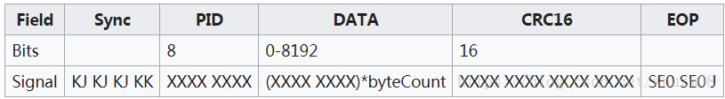
A data packet consists of the PID followed by 0–1,024 bytes of data payload (up to 1,024 bytes for high-speed devices, up to 64 bytes for full-speed devices, and at most eight bytes for low-speed devices),
[162]
and a 16-bit CRC.
There are two basic forms of data packet,
DATA0
and
DATA1
. A data packet must always be preceded by an address token, and is usually followed by a handshake token from the receiver back to the transmitter. The two packet types provide the 1-bit sequence number required by
stop-and-wait ARQ
. If a USB host does not receive a response (such as an ACK) for data it has transmitted, it does not know if the data was received or not; the data might have been lost in transit or it might have been received but the handshake response was lost.
To solve this problem, the device keeps track of the type of DATAx packet it last accepted. If it receives another DATAx packet of the same type, it is acknowledged but ignored as a duplicate. Only a DATAx packet of the opposite type is actually received.
If the data is corrupted while transmitted or received, the CRC check fails. When this happens, the receiver does not generate an ACK, which makes the sender resend the packet.
When a device is reset with a SETUP packet, it expects an 8-byte DATA0 packet next.
USB 2.0 added
DATA2
and
MDATA
packet types as well. They are used only by high-bandwidth devices doing high-bandwidth isochronous transfers that must transfer more than 1024 bytes per 125 µs micro frame
(8,192 kb/s).
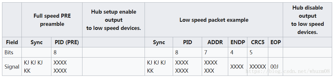
PRE packet (tells hubs to temporarily switch to low speed mode)
A hub is able to support low bandwidth devices mixed with other speed device via a special PID value,
PRE
. This is required as a USB hub functions as a very simple repeater, broadcasting the host message to all connected devices regardless if the packet was for it or not. This means in a mixed speed environment, there is a potential danger that a low speed could misinterpret a high or full speed signal from the host.
当hub仅仅只是一个简单的中继器,host的消息转发到所有端口上,这样低速设备可能就会误解高速消息。
To eliminate this danger, if a USB hub detects a mix of high speed or full speed and low speed devices, it, by default, disables communication to the low speed device unless it receives a request to switch to low speed mode. On reception of a PRE packet however, it temporarily re-enables the output port to all low speed devices, to allow the host to send a single low speed packet to low speed devices. After the low speed packet is sent, an end of packet (EOP) signal tells the hub to disable all outputs to low speed devices again.
为了消除这种危险,hub当检测到高速设备和低速设备混合环境时,默认disable低速设备对应的端口,即高速消息不转发到低速设备对应的端口上,如果host想和低速设备通信,则发一个PRE包给hub,hub临时的enable低速端口,紧接着发消息包给低速设备,当hub检测到包结束EOP信号时,又自动disable低速设备对应的端口。
Transaction
OUT transaction
IN transaction
SETUP transaction
This is used for device enumeration and connection management and informs the device that the host would like to start a control transfer exchange.
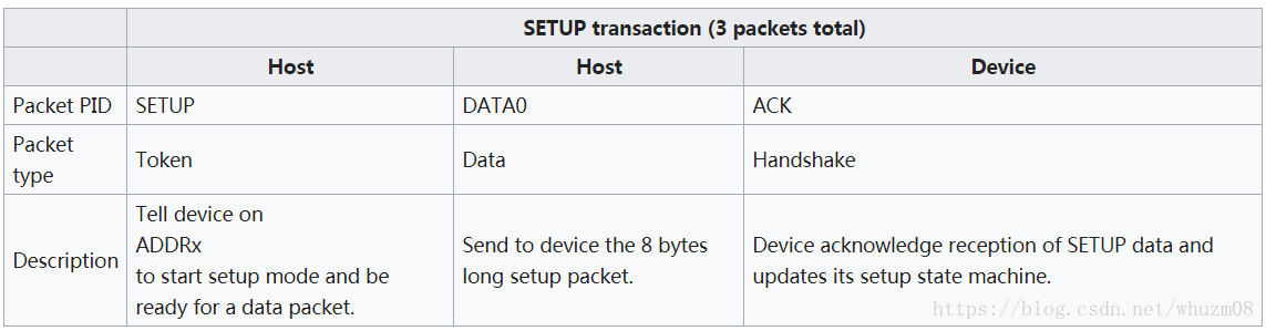
- Depending on the setup packet, an optional data packet from device to host or host to device may occur.
Control transfer exchange[edit]
The control transfer exchange consist of three distinct stages:
- Setup stage: This is the setup command sent by the host to the device.
- Data stage (optional): The device may optionally send data in response to a setup request.
- Status stage: Dummy IN or OUT transaction, which is probably for indicating the end of a control transfer exchange.
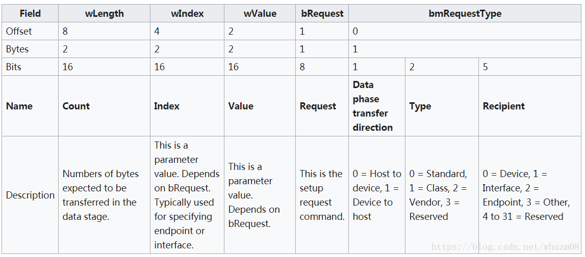
This allows the host to perform bus management action like enumerating new USB devices via retrieving the new device
device descriptors. Retrieval of the device descriptors would especially allow for determining the USB Class, VID, and PID, which are often used for determining the correct USB driver for the device.
Also, after the device descriptor is retrieved, the host performs another control transfer exchange, but instead to set the address of the USB device to a new ADDRx.
System Configuration
Attachment of USB Devices
All USB devices attach to the USB through ports on specialized USB devices known as hubs. Hubs have
status bits that are used to report the attachment or removal of a USB device on one of its ports. The host
queries the hub to retrieve these bits. In the case of an attachment, the host enables the port and addresses
the USB device through the device’s control pipe at the default address.
The host assigns a unique USB address to the device and then determines if the newly attached USB device
is a hub or a function. The host establishes its end of the control pipe for the USB device using the assigned
USB address and endpoint number zero.
Removal of USB Devices
When a USB device has been removed from one of a hub’s ports, the hub disables the port and provides an
indication of device removal to the host. The removal indication is then handled by appropriate USB
System Software. If the removed USB device is a hub, the USB System Software must handle the removal
of both the hub and of all of the USB devices that were previously attached to the system through the hub.
Bus Enumeration
Bus enumeration is the activity that identifies and assigns unique addresses to devices attached to a bus.
Because the USB allows USB devices to attach to or detach from the USB at any time, bus enumeration is
an on-going activity for the USB System Software.
1. The hub to which the USB device is now attached informs the host of the event via a reply on its status
change pipe. At this point, the USB device is in the
Powered state and the port to which it is attached is disabled.
2. The host determines the exact nature of the change by querying the hub.
3. Now that the host knows the port to which the new device has been attached, the host then waits for at
least 100 ms to allow completion of an insertion process and for power at the device to become stable.
The host then issues a port enable and reset command to that port.
4. The hub performs the required reset processing for that port. When the reset
signal is released, the port has been enabled. The USB device is now in the Default state and can draw
no more than 100 mA from V
BUS
. All of its registers and state have been reset and it answers to the
default address.
5. The host assigns a unique address to the USB device, moving the device to the Address state.
6. Before the USB device receives a unique address, its Default Control Pipe is still accessible via the
default address. The host reads the device descriptor to determine what actual maximum data payload
size this USB device’s default pipe can use.
7. The host reads the configuration information from the device by reading each configuration zero to
n
-1, where
n
is the number of configurations. This process may take several milliseconds to complete.
8. Based on the configuration information and how the USB device will be used, the host assigns a
configuration value to the device. The device is now in the Configured state and all of the endpoints in
this configuration have taken on their described characteristics. The USB device may now draw the
amount of V
BUS
power described in its descriptor for the selected configuration. From the device’s
point of view, it is now ready for use.
Hub Specification
A hub consists of three components: the Hub Repeater, the Hub Controller, and the Transaction Translator.
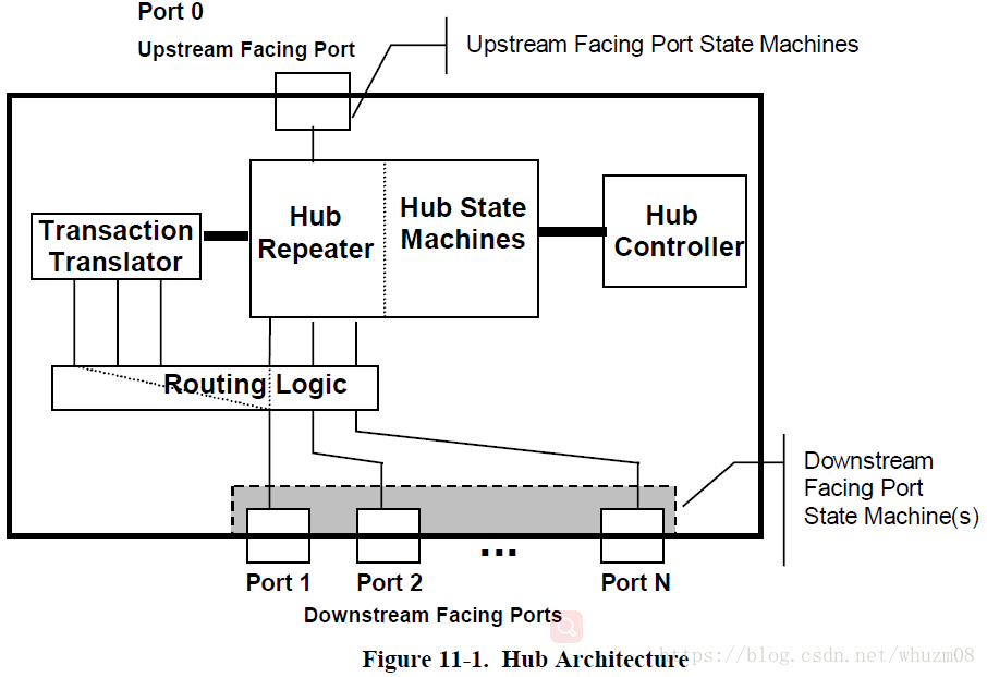
The Hub Repeater is responsible for managing connectivity between upstream and downstream facing ports
which are operating at the same speed. The Hub Repeater supports full-/low-speed connectivity and highspeed
connectivity. The Hub Controller provides status and control and permits host access to the hub. The
Transaction Translator takes high-speed split transactions and translates them to full-/low-speed transactions
when the hub is operating at high-speed and has full-/low-speed devices attached. The operating speed of a
device attached on a downstream facing port determines whether the Routing Logic connects a port to the
Transaction Translator or hub repeater sections.
When a hub’s upstream facing port is attached to an electrical environment that is operating at full-/lowspeed,
the hub’s high-speed functionality is disallowed. This means that the hub will only operate at full-
/low-speed and the transaction translator and high-speed repeater will not operate. In this electrical
environment, the hub repeater must operate as a full-/low-speed repeater and the routing logic connects
ports to the hub repeater.
When the hub upstream facing port is attached to an electrical environment that is operating at high-speed,
the full-/low-speed hub repeater is not operational. In this electrical environment when a high-speed device
is attached on downstream facing port, the routing logic will connect the port to the hub repeater and the
hub repeater must operate as a high-speed repeater. In this case, when a full-/low-speed device is attached
on a downstream facing port, the routing logic must connect the port to the transaction translator.
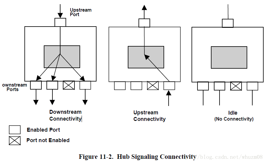
If a downstream facing port is enabled (i.e., in a state where it can propagate signaling through the hub), and
the hub detects the start of a packet on that port, connectivity is established in an upstream direction to the
upstream facing port of that hub, but not to any other downstream facing ports. This means that when a
device or a hub transmits a packet upstream, only those hubs in line between the transmitting device and the
host will see the packet.
In the downstream direction, hubs operate in a broadcast mode. When a hub detects the start of a packet on
its upstream facing port, it establishes connectivity to all enabled downstream facing ports. If a port is not
enabled, it does not propagate packet signaling downstream.
Hub Controller
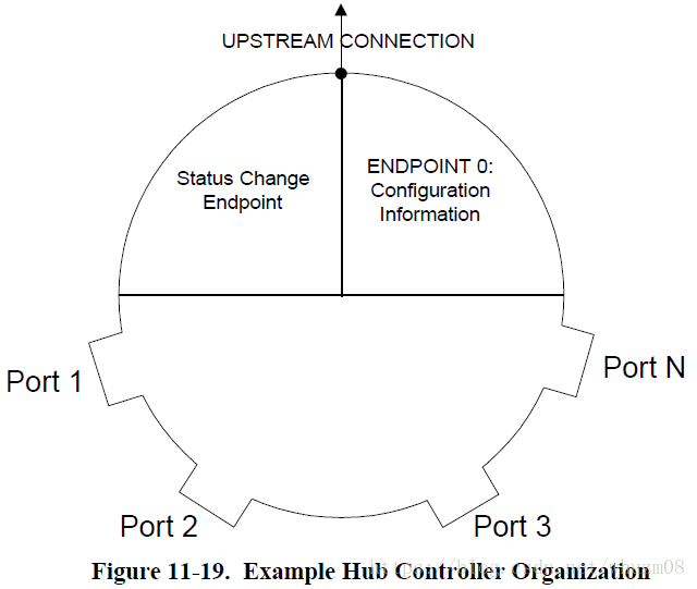
The Hub Class defines one additional endpoint beyond Default Control Pipe, which is required for all hubs:
the Status Change endpoint. The host system receives port and hub status change notifications through the
Status Change endpoint
.The Status Change endpoint is an interrupt endpoint. If no hub or port status
change bits are set, then the hub returns an NAK when the Status
Change endpoint is polled. When a status
change bit is set, the hub responds with data, indicating the entity (hub or port)
with a change bit set. The USB System Software can use this data to determine which status registers to
access in order to determine the exact cause of the status change interrupt.
Hub也是一个USB device,但是一个特殊的USB device
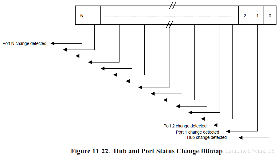
Hubs report this value in byte-increments. That is, if a
hub has six ports, it returns a byte quantity, and reports a zero in the invalid port number field locations.
The USB System Software is aware of the number of ports on a hub (this is reported in the hub descriptor)
and decodes the Hub and Port Status Change Bitmap accordingly.
参考资料:
IEC international standard: IEC 62680 Universal serial bus interfaces for data and power:
- IEC 62680-1.1:2015 - Part 1-1: Common components - USB Battery Charging Specification, revision 1.2
- IEC 62680-1-2:2016 - Part 1-2: Common components - USB Power Delivery specification revision 1.0
- IEC 62680-1-3:2016 - Part 1-3: Universal Serial Bus interfaces - Common components -, revision 1.0
- IEC 62680-2-1:2015 - Part 2-1: Universal Serial Bus Specification, Revision 2.0 (http://sdphca.ucsd.edu/Lab_Equip_Manuals/usb_20.pdf)
- IEC 62680-2-2:2015 - Part 2-2: Micro-USB Cables and Connectors Specification, Revision 1.01
- IEC 62680-2-3:2015 - Part 2-3: Universal Serial Bus Cables and Connectors Class Document Revision 2.0


 482
482

 被折叠的 条评论
为什么被折叠?
被折叠的 条评论
为什么被折叠?
 到【灌水乐园】发言


