


 本文详细描述了一个网络拓扑实验,涉及IP地址规划、DHCP配置、静态路由设置以及如何防止环路,包括R1至R6路由器的配置实例,旨在实现最佳选路、小型路由表和访问权限控制。
拓扑图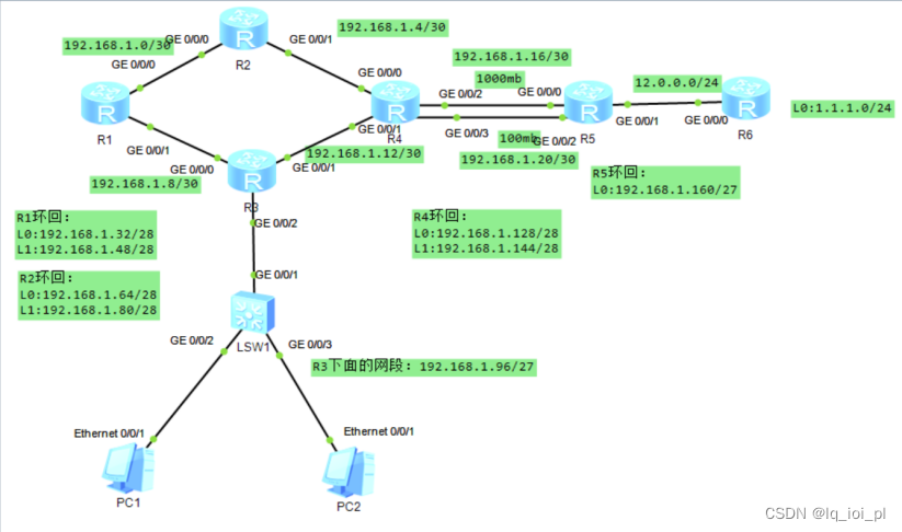 题目
题目
1.R6为ISP,接口IP地址均为公有地址,该设备只能配置IP地址,之后不能再对其进行任何配置;
2.R1-R5为局域网,私有IP地址192.168.1.0/24,请合理分配;
3.R1、R2、R4,各有两个环回IP地址;R5,R6各有一个环回地址;所有路由器上环回均代表连接用户的接口;
4.R3下面的两台PC通过DHCP自动获取IP地址;
5.选路最佳,路由表尽量小,避免环路;
6.R1-R5均可以访问R6的环回;
7.R6 telnet R5的公有地址时,实际登录到R1上;
8.R4与R5正常通过1000M链路,故障时通过100m链路。
三、实验思路
1.划分IP地址,将各设备的IP地址进行配置
分析:从拓扑图中看出,可以将192.168.1.0/24划分为6个大的网段(从主机位借三位192.168.1.0/27),然后再根据这6个大的网段进行细分
(1)192.168.1.0000 0000---192.168.1.0/27---骨干链路
192.168.1.0000 0000---192.168.1.0/30
192.168.1.0000 0100---192.168.1.0/30
192.168.1.0000 1000---192.168.1.0/30
192.168.1.0000 1100---192.168.1.0/30
192.168.1.0001 0000---192.168.1.0/30
192.168.1.0001 0100---192.168.1.0/30
192.168.1.0001 1000---192.168.1.0/30
192.168.1.0001 1100---192.168.1.0/30
(2)192.168.1.0010 0000---192.168.1.32/27---R1环回
192.168.1.0010 0000---192.168.1.32/28
192.168.1.0011 0000---192.168.1.48/28
(3)192.168.1.0100 0000---192.168.1.64/27---R2环回
192.168.1.0100 0000---192.168.1.64/28
192.168.1.0101 0000---192.168.1.80/28
(4)192.168.1.0110 0000---192.168.1.96/27---R3底下的用户
(5)192.168.1.1000 0000---192.168.1.128/27---R4环回
192.168.1.1000 0000---192.168.1.128/28
192.168.1.1001 0000---192.168.1.144/28
(6)192.168.1.1010 0000---192.168.1.32/27---R5环回
(7)192.168.1.1000 0000---192.168.1128/27
(8)192.168.1.1010 0000---192.168.1.160/27
2.配置DHCP使获取R3下面两台PC自动获取IP地址
3.配置静态路由
4.防止成环,R1\R2\R4\R5设置空接口
5.设置net,使R1-R5可以访问R6
6.R4与R5正常通过1000M链路,故障时通过100m链路
- R6 telnet R5的公有地址时,实际登录到R1上
- 实验步骤
- 配置IP地址
[R1]int g0/0/0
[R1-GigabitEthernet0/0/0]ip address 192.168.1.1 30
[R1-GigabitEthernet0/0/0]int g0/0/1
[R1-GigabitEthernet0/0/1]ip address 192.168.1.9 30
[R1-GigabitEthernet0/0/1]int loo0
[R1-LoopBack0]ip address 192.168.1.33 28
[R1-LoopBack0]int loo1
[R1-LoopBack1]ip address 192.168.1.49 28
[R1-LoopBack1]
-------------------------------------------------------------------
[R2]int g0/0/0
[R2-GigabitEthernet0/0/0]ip add 192.168.1.2 30
[R2-GigabitEthernet0/0/0]int g0/0/1
[R2-GigabitEthernet0/0/1]ip add 192.168.1.5 30
[R2-GigabitEthernet0/0/1]int loo0
[R2-LoopBack0]ip add 192.168.1.65 28
[R2-LoopBack0]int loo1
[R2-LoopBack1]ip add 192.168.1.81 28
[R2-LoopBack1]
-------------------------------------------------------------------------
[R3-GigabitEthernet0/0/2]ip address 192.168.1.97 27
[R3]int g0/0/0
[R3-GigabitEthernet0/0/0]ip add 192.168.1.10 30
[R3-GigabitEthernet0/0/0]int g0/0/1
[R3-GigabitEthernet0/0/1]ip add 192.168.1.13 30
[R3-GigabitEthernet0/0/1]
-------------------------------------------------------------------------
[R4]int g0/0/0
[R4-GigabitEthernet0/0/0]ip add 192.168.1.6 30
[R4-GigabitEthernet0/0/0]int g0/0/1
[R4-GigabitEthernet0/0/1]ip add 192.168.1.14 30
[R4-GigabitEthernet0/0/1]int g0/0/2
[R4-GigabitEthernet0/0/2]ip add 192.168.1.17 30
[R4-GigabitEthernet0/0/2]int g0/0/3
[R4-GigabitEthernet0/0/3]ip add 192.168.1.21 30
[R4-GigabitEthernet0/0/3]int loo0
[R4-LoopBack0]ip add 192.168.1.129 28
[R4-LoopBack0]int loo1
[R4-LoopBack1]ip add 192.168.1.145 28
[R4-LoopBack1]
---------------------------------------------------------------------------
[R5]int g0/0/0
[R5-GigabitEthernet0/0/0]ip add 192.168.1.18 30
[R5-GigabitEthernet0/0/0]int g0/0/1
[R5-GigabitEthernet0/0/1]ip add 12.0.0.1 24
[R5-GigabitEthernet0/0/0]int g0/0/2
[R5-GigabitEthernet0/0/2]ip add 192.168.1.22 30
[R5-GigabitEthernet0/0/2] int loo0
[R5-LoopBack0]ip add 192.168.1.161 27
[R5-LoopBack0]
------------------------------------------
[R6]int g0/0/0
[R6-GigabitEthernet0/0/0]ip add 12.0.0.2 24
[R6-GigabitEthernet0/0/0]int LoopBack 0
[R6-LoopBack0]ip add 1.1.1.1 24
[R6-LoopBack0]
- 配置DHCP使获取R3下面两台PC自动获取IP地址
[R3]ip pool aa
[R3-ip-pool-aa]net 192.168.1.96 mask 27
[R3-ip-pool-aa]g
[R3-ip-pool-aa]gateway-list 192.168.1.97
[R3-ip-pool-aa]dns-list 114.114.114.114
[R3-ip-pool-aa]int g0/0/2
[R3-GigabitEthernet0/0/2]dhcp se g
[R3-GigabitEthernet0/0/2]
查看IP地址

3.配置静态路由
[R1]ip route-static 192.168.1.4 30 192.168.1.2
[R1]ip route-static 192.168.1.64 27 192.168.1.2
[R1]ip route-static 192.168.1.16 30 192.168.1.2
[R1]ip route-static 192.168.1.20 30 192.168.1.2
[R1]ip route-static 192.168.1.128 27 192.168.1.2
[R1]ip route-static 192.168.1.160 27 192.168.1.2
[R1]ip route-static 192.168.1.96 27 192.168.1.10
[R1]ip route-static 192.168.1.12 30 192.168.1.10
[R1]
------------------------------------------------------------------------
[R2]ip route-static 192.168.1.8 30 192.168.1.1
[R2]ip route-static 192.168.1.32 27 192.168.1.1
[R2]ip route-static 192.168.1.96 27 192.168.1.1
[R2]ip route-static 192.168.1.12 30 192.168.1.6
[R2]ip route-static 192.168.1.128 27 192.168.1.6
[R2]ip route-static 192.168.1.16 30 192.168.1.6
[R2]ip route-static 192.168.1.20 30 192.168.1.6
[R2]ip route-static 192.168.1.160 27 192.168.1.6
[R2]
-----------------------------------------------------------------------
[R3]ip route-static 192.168.1.32 27 192.168.1.9
[R3]ip route-static 192.168.1.0 30 192.168.1.9
[R3]ip route-static 192.168.1.64 27 192.168.1.9
[R3]ip route-static 192.168.1.4 30 192.168.1.14
[R3]ip route-static 192.168.1.16 30 192.168.1.14
[R3]ip route-static 192.168.1.20 30 192.168.1.14
[R3]ip route-static 192.168.1.128 27 192.168.1.14
[R3]ip route-static 192.168.1.160 27 192.168.1.14
[R3]
--------------------------------------------------------------------------
[R4]ip route-static 192.168.1.160 27 192.168.1.18
[R4]ip route-static 192.168.1.160 27 192.168.1.22
[R4]ip route-static 192.168.1.96 27 192.168.1.13
[R4]ip route-static 192.168.1.8 30 192.168.1.13
[R4]ip route-static 192.168.1.32 27 192.168.1.13
[R4]ip route-static 192.168.1.64 27 192.168.1.5
[R4]ip route-static 192.168.1.0 30 192.168.1.5
[R4]
--------------------------------------------------------------------
[R5]ip route-static 192.168.1.0 24 192.168.1.17
[R5]ip route-static 192.168.1.0 24 192.168.1.21
[R5]


4.防止成环,R1\R2\R4\R5设置空接口
[R1]ip route-s 192.168.1.32 27 NULL 0
[R1]
[R2]ip route-s 192.168.1.64 27 NULL 0
[R2]
[R4]ip route-s 192.168.1.128 27 NULL 0
[R4]
[R5]ip route-s 192.168.1.160 27 NULL 0
[R5]
5.设置net,使R1-R5可以访问R6
[R5]acl 2000
[R5-acl-basic-2000]ru per sou 192.168.1.0 0.0.0.255
[R5-acl-basic-2000]int g0/0/1
[R5-GigabitEthernet0/0/1]nat out 2000
[R5-GigabitEthernet0/0/1]
6.R4与R5正常通过1000M链路,故障时通过100m链路
[R1]ip rou 192.168.1.20 30 192.168.1.2 pre 61
Info: Succeeded in modifying route.
[R1]ip rou 192.168.1.20 30 192.168.1.10 pre 61
[R1]
[R2]ip rou 192.168.1.20 30 192.168.1.6 pre 61
Info: Succeeded in modifying route.
[R2]
[R3]ip rou 192.168.1.20 30 192.168.1.14 pre 61
Info: Succeeded in modifying route.
[R3]
[R4]ip rou 0.0.0.0 0 192.168.1.22 pre 61
Info: Succeeded in modifying route.
[R4]
[R5]ip rou 192.168.1.0 24 192.168.1.21 pre 61
Info: Succeeded in modifying route.
[R5]
- R6 telnet R5的公有地址时,实际登录到R1上
[R1]aaa
[R1-aaa]lo ad pri le 15 pass c 123456
Info: Add a new user.
[R1-aaa]local-user admin service-type telnet
[R1-aaa]q
[R1]user-i vty 0 4
[R1-ui-vty0-4]auth
[R1-ui-vty0-4]authentication-mode aaa
[R1-ui-vty0-4]
[R5]int g0/0/1
[R5-GigabitEthernet0/0/1]nat ser pro tcp glo curr 23 in 192.168.1.1 23
Warning:The port 23 is well-known port. If you continue it may cause function failure.
Are you sure to continue?[Y/N]:y
[R5-GigabitEthernet0/0/1]
<R6>telnet 12.0.0.1
Press CTRL_] to quit telnet mode
Trying 12.0.0.1...
Connected to 192.168.1.1 ...
Login authentication
Username:admin
Password:
<R1>


 2233
2233


 被折叠的 条评论
为什么被折叠?
被折叠的 条评论
为什么被折叠?
 到【灌水乐园】发言


