


 本文介绍了如何利用AT32F421单片机的基础定时器TMR6和通用定时器TMR3实现2秒延时、PWM波输出及捕获功能。通过设置定时器的周期寄存器pr和分频系数div,调整PWM的频率和占空比。同时,文章展示了在不同模式下如何配置TMR3的通道1和2,分别用于PWM输出和捕获,并提供了详细的代码实现。
前言
用AT32F421的基础定时器TMR6配合中断实现定时功能,用通用定时器TMR3实现PMW波的输出与捕获。本文记录了测试AT32F4单片机定时器的过程。
环境
- VScode ( EIDE + Cortex Debug )
- Open On-Chip Debugger 0.11.0+dev-snapshot
- GCC toolchain
- AT32F421C8T7系统板 & ATLink
- USB < - > TTL 模块
功能描述
复位后,用TMR6定时2s,如果在此2s内PC13按键按下,则立即进入产生PWM的模式;如果2s没有按键按下,则进入外部PWM输入的捕获模式。
- PWM产生:使用通用定时器TMR3的通道1——IOMUX映射到PA6输出。要求能指定PWM频率和占空比。
- PWM捕获:使用通用定时器TMR3的通道2——IOMUX映射到PA7输入。计算出该PWM的频率和占空比。
代码实现
- pulse_capture.c
#include "pulse_capture.h" // #define AHB_FREQ 120 extern crm_clocks_freq_type crm_clocks_freq_struct; /** * @brief generate a PWM wave with specified period and duty cycle * @param priority: getting maximum accuracy in PWM dutycycle for DUTYCYCLE priority, * getting maximum accuracy in PWM period/frequency for PERIOD priority. * @param period_us: in DUTYCYCLE prioity, this value must be integer in [547, 35e6] with unit us (<0.1Hz ~ 1.831kHz). * The limitation comes from TMR3_DIV taking values between 0 and 65535 with TMR3_PR==0xFFFF. * in PERIOD prioity, this value must be integer in [1, 546] with unit us (1.831kHz ~ 60MHz). * The limitation comes from TMR3_DIV taking values between 0 and 65535 with TMR3_PR==0xFFFF. * @param duty_cycle: float value between 0 and 1. * @param pulse_type: effective level (when CxDT > CVAL) is 0 for NEGATIVE pulse type, * effective level (when CxDT > CVAL) is 1 for POSITIVE pulse type. * @retval none */ uint8_t sigle_pwm_gen(accuracy_priority_type priority, uint32_t period_us, float32_t duty_cycle, pulse_effective_type pulse_type, confirm_state one_cycle) { uint16_t div = 0; uint16_t pr = 0; uint32_t pulse_width = 0; uint32_t current_ch_val = 0; if(priority==DUTYCYCLE) { /* 将PR设置为最大值0xFFFF以获得对占空比的最细细分 */ pr=0xFFFF; /* 改变 div 以设置PWM的频率 */ div = period_us * (float32_t)crm_clocks_freq_struct.ahb_freq/1000000 / (pr+1) + 0.5 - 1; if(div<0 || div>0xFFFF) { printf("param 'period_us' should be in [547, 35e6] us but got %ld, causing div==%d.\r\n",period_us,div); return 0xFF; } } else { /* 不对TMR3时钟分频 以获得对周期的最细细分 */ div=0; /* 改变 pr 以设置PWM的频率 */ pr= period_us * (float32_t)crm_clocks_freq_struct.ahb_freq/1000000 / (div+1) + 0.5 - 1; if(pr<0 || pr>0xFFFF) { printf("param 'period_us' should be in [1, 546] us but got %ld, causing pr==%d.\r\n",period_us,div); return 0xFE; } } tmr_base_init(TMR3, pr , div); // // 设置TMR3溢出事件只能由TMR3计数溢出产生,不允许软件触发和从定时器。 // TMR3->ctrl1_bit.ovfs=1; // 禁止溢出事件 TMR3->ctrl1_bit.ovfen=1; tmr_cnt_dir_set(TMR3, TMR_COUNT_UP); tmr_clock_source_div_set(TMR3, TMR_CLOCK_DIV1); /* 通道 1 输出配置 */ tmr_output_config_type tmr_oc_init_structure; tmr_output_default_para_init(&tmr_oc_init_structure); if (pulse_type == POSITIVE) { tmr_oc_init_structure.oc_mode = TMR_OUTPUT_CONTROL_PWM_MODE_A; tmr_oc_init_structure.oc_idle_state = FALSE; // C1OUT 的有效电平为高 tmr_oc_init_structure.oc_polarity = TMR_OUTPUT_ACTIVE_HIGH; } else //负脉冲,有效为低电平,无效或者IDLE状态为高电平 { tmr_oc_init_structure.oc_mode = TMR_OUTPUT_CONTROL_PWM_MODE_B; tmr_oc_init_structure.oc_idle_state = TRUE; tmr_oc_init_structure.oc_polarity = TMR_OUTPUT_ACTIVE_LOW; } tmr_oc_init_structure.oc_output_state = TRUE; if (one_cycle) { /* 单脉冲 */ tmr_one_cycle_mode_enable(TMR3, TRUE); } /* 设置通道的计数值 */ if (0 < duty_cycle && duty_cycle <= (float32_t)65535 / 65536) { pulse_width = duty_cycle * (pr + 1); } else { pulse_width = pr; // TOTO: 理想情况下,这里占空比应该为1,但无论d1ct取多少都不可能做到,因为PWM-A的最大占空比就是65535/65536。 } /* output to TMR 3 channel 1 */ tmr_output_channel_config(TMR3, TMR_SELECT_CHANNEL_1, &tmr_oc_init_structure); tmr_channel_value_set(TMR3, TMR_SELECT_CHANNEL_1, pulse_width); current_ch_val = tmr_channel_value_get(TMR3, TMR_SELECT_CHANNEL_1); printf("TMR 3 C1 config... current C1DT: %ld \r\n", current_ch_val); /* tmr it enable */ tmr_interrupt_enable(TMR3, TMR_C1_INT, TRUE); tmr_channel_enable(TMR3, TMR_SELECT_CHANNEL_1, TRUE); /* 选择输入触发源 */ // tmr_trigger_input_select(TMR3, TMR_SUB_INPUT_SEL_C2DF2); /* 从模式配置:选择次定时器的模式为触发模式 */ // tmr_sub_mode_select(TMR3, TMR_SUB_TRIGGER_MODE); /*TMR3 输出总开关打开 */ // tmr_output_enable(TMR3, TRUE);// 这是置位 刹车oen,然而TMR3没有刹车 /*使能 TMR3 */ tmr_counter_enable(TMR3, TRUE); // tmr_event_sw_trigger(TMR3,TMR_C1_SWTRIG); // tmr_event_sw_trigger(TMR3,TMR_TRIGGER_SWTRIG); return 1; } /** * @brief capture the external PWM inputed from PA7 (TMR3 C2) * @param none * @retval none */ void sigle_pwm_cap(void) { tmr_input_config_type tmr_ic_init_structure; tmr_input_default_para_init(&tmr_ic_init_structure); tmr_ic_init_structure.input_filter_value = 0; tmr_ic_init_structure.input_channel_select = TMR_SELECT_CHANNEL_2; tmr_ic_init_structure.input_mapped_select = TMR_CC_CHANNEL_MAPPED_DIRECT; tmr_ic_init_structure.input_polarity_select = TMR_INPUT_RISING_EDGE; tmr_pwm_input_config(TMR3, &tmr_ic_init_structure, TMR_CHANNEL_INPUT_DIV_1); /* select the tmr3 input trigger: C2IF2 */ tmr_trigger_input_select(TMR3, TMR_SUB_INPUT_SEL_C2DF2); /* select the sub mode: reset mode */ tmr_sub_mode_select(TMR3, TMR_SUB_RESET_MODE); /* enable the sub sync mode */ tmr_sub_sync_mode_set(TMR3, TRUE); /* tmr enable counter */ tmr_counter_enable(TMR3, TRUE); /* enable the c2 interrupt request */ tmr_interrupt_enable(TMR3, TMR_C2_INT, TRUE); } - main.c
/** ************************************************************************** * @file main.c * @version v2.0.5 * @date 2022-09-26 * @brief main program */ #include "systick.h" #include "usart.h" #include "usrkey.h" #include "stdio.h" #include "at32f421_clock.h" #include "pulse_capture.h" /** * @brief main function. * @param none * @retval none */ // 指示当前MCU是发出PWM还是接收PWM,该变量只在main.c中使用 static char TX = 0; /* 由于使用硬件的溢出标志必然导致反复进入ISR而无法在主程序中被读取, 所以另起一全局变量作为溢出标志。该变量定义在at32f421_int.c中 */ extern char TIM6OVF; // 接收到的PWM波的参数,随时可能被ISR修改 __IO uint16_t PWMin_dutycycle = 0; __IO uint32_t PWMin_frequency = 0; // 获取系统时钟 crm_clocks_freq_type crm_clocks_freq_struct = {0}; int main(void) { system_clock_config(); delay_init(); crm_clocks_freq_get(&crm_clocks_freq_struct); // =============================> PC13 init <============================= /* PC13配置成内部上拉的输入模式 */ gpio_init_type gpio_init_struct; crm_periph_clock_enable(CRM_GPIOC_PERIPH_CLOCK, TRUE); gpio_default_para_init(&gpio_init_struct); gpio_init_struct.gpio_drive_strength = GPIO_DRIVE_STRENGTH_STRONGER; gpio_init_struct.gpio_out_type = GPIO_OUTPUT_PUSH_PULL; gpio_init_struct.gpio_mode = GPIO_MODE_INPUT; gpio_init_struct.gpio_pins = GPIO_PINS_13; gpio_init_struct.gpio_pull = GPIO_PULL_UP; gpio_init(GPIOC, &gpio_init_struct); // =============================> USART init <============================= uart_print_init(115200); /* output a message on hyperterminal using printf function */ printf("waiting for user key (PC13) pressing down...\r\n"); // =============================> TIM 6 init <============================= crm_periph_clock_enable(CRM_TMR6_PERIPH_CLOCK, TRUE); /* 配置定时器 TMRx_DIV 寄存器和 TMRx_PR 寄存器 */ /* ahb_freq/24k/10k = 0.5hz */ /* pr+1 = 10k , div+1 = 24k */ // 注意!tmr_base_init()将会软件触发一次定时器溢出中断。 // 然而在ISR中调用了printf(),但是此时USART尚未初始化,因此程序会卡死。 // 所以USART初始化应在TIM初始化之前! tmr_base_init(TMR6, 9999, (crm_clocks_freq_struct.ahb_freq / 5000) - 1); /* 向上计数(默认) */ tmr_cnt_dir_set(TMR6, TMR_COUNT_UP); /* 开启定时器溢出中断 */ tmr_interrupt_enable(TMR6, TMR_OVF_INT, TRUE); /* 开启 NVIC 溢出中断 */ nvic_priority_group_config(NVIC_PRIORITY_GROUP_4); // // 开启之前先清除中断标志位,以免反复进入ISR。(除非已在在ISR结尾清除) // tmr_flag_clear(TMR6, TMR_OVF_FLAG); nvic_irq_enable(TMR6_GLOBAL_IRQn, 1, 0); // ===========================> TX/RX selection <=========================== // TX = 0; // 只进行1个计数周期 tmr_one_cycle_mode_enable(TMR6, TRUE); // 之前设置TIM6时软件产生了溢出事件,开启定时前先清除全局标志 TIM6OVF = 0; // 开启定时器计数 tmr_counter_enable(TMR6, TRUE); // 既没有计时到时,也没有按键按下,则进入循环。 while (TIM6OVF == 0 && TX == 0) { usrkey_state_type current_key_state; current_key_state = usrkey_state(); if (current_key_state == PRESS_DOWN) { TX = 1; // 停止TIM6计时 // tmr_counter_enable(TMR6, FALSE); tmr_reset(TMR6); break; } } // =============================> TIM 3 init <============================= crm_periph_clock_enable(CRM_TMR3_PERIPH_CLOCK, TRUE); nvic_priority_group_config(NVIC_PRIORITY_GROUP_4); nvic_irq_enable(TMR3_GLOBAL_IRQn, 0, 0); /* tmr it enable */ tmr_interrupt_enable(TMR3, TMR_C1_INT | TMR_OVF_INT, TRUE); // ===============================> main loop <=============================== if (TX == 1) { /* LED */ gpio_init_struct.gpio_drive_strength = GPIO_DRIVE_STRENGTH_STRONGER; gpio_init_struct.gpio_out_type = GPIO_OUTPUT_PUSH_PULL; gpio_init_struct.gpio_mode = GPIO_MODE_OUTPUT; gpio_init_struct.gpio_pins = GPIO_PINS_13; gpio_init_struct.gpio_pull = GPIO_PULL_NONE; gpio_init(GPIOC, &gpio_init_struct); /* 配置 TMR 3 输出管脚 PA6 */ crm_periph_clock_enable(CRM_GPIOA_PERIPH_CLOCK, TRUE); gpio_init_struct.gpio_pins = GPIO_PINS_6; gpio_init_struct.gpio_mode = GPIO_MODE_MUX; gpio_init_struct.gpio_out_type = GPIO_OUTPUT_PUSH_PULL; gpio_init_struct.gpio_pull = GPIO_PULL_NONE; gpio_init_struct.gpio_drive_strength = GPIO_DRIVE_STRENGTH_STRONGER; gpio_init(GPIOA, &gpio_init_struct); gpio_pin_mux_config(GPIOA, GPIO_PINS_SOURCE6, GPIO_MUX_1); /* 在PA6产生PWM */ uint8_t state = sigle_pwm_gen(PERIOD ,100, (float32_t) 0.2, POSITIVE, FALSE); while (1) { if(state==1) { // LED blink GPIOC->odt ^= GPIO_PINS_13; delay_ms(300); GPIOC->odt ^= GPIO_PINS_13; delay_ms(300); } } } else { /* 配置 TMR 3 输入管脚 PA7 */ crm_periph_clock_enable(CRM_GPIOA_PERIPH_CLOCK, TRUE); gpio_default_para_init(&gpio_init_struct); gpio_init_struct.gpio_pins = GPIO_PINS_7; gpio_init_struct.gpio_out_type = GPIO_OUTPUT_PUSH_PULL; gpio_init_struct.gpio_pull = GPIO_PULL_NONE; gpio_init_struct.gpio_mode = GPIO_MODE_MUX; gpio_init_struct.gpio_drive_strength = GPIO_DRIVE_STRENGTH_STRONGER; gpio_init(GPIOA, &gpio_init_struct); gpio_pin_mux_config(GPIOA, GPIO_PINS_SOURCE7, GPIO_MUX_1); sigle_pwm_cap(); while (1) { printf("Frequency = %ld Hz, Dutycycle = %d%%\r\n", PWMin_frequency, PWMin_dutycycle); } } } - at32f421_int.c
/**
 **************************************************************************
 * @file     at32f421_int.c
 * @version  v2.0.5
 * @date     2022-04-02
 * @brief    main interrupt service routines.
 **************************************************************************
 *                       Copyright notice & Disclaimer
 *
 * The software Board Support Package (BSP) that is made available to
 * download from Artery official website is the copyrighted work of Artery.
 * Artery authorizes customers to use, copy, and distribute the BSP
 * software and its related documentation for the purpose of design and
 * development in conjunction with Artery microcontrollers. Use of the
 * software is governed by this copyright notice and the following disclaimer.
 *
 * THIS SOFTWARE IS PROVIDED ON "AS IS" BASIS WITHOUT WARRANTIES,
 * GUARANTEES OR REPRESENTATIONS OF ANY KIND. ARTERY EXPRESSLY DISCLAIMS,
 * TO THE FULLEST EXTENT PERMITTED BY LAW, ALL EXPRESS, IMPLIED OR
 * STATUTORY OR OTHER WARRANTIES, GUARANTEES OR REPRESENTATIONS,
 * INCLUDING BUT NOT LIMITED TO, THE IMPLIED WARRANTIES OF MERCHANTABILITY,
 * FITNESS FOR A PARTICULAR PURPOSE, OR NON-INFRINGEMENT.
 *
 **************************************************************************
 */

/* includes ------------------------------------------------------------------*/
#include "at32f421_int.h"
#include "stdio.h"


char TIM6OVF = 0;

extern crm_clocks_freq_type crm_clocks_freq_struct;

extern uint16_t PWMin_dutycycle;
extern uint32_t PWMin_frequency;

__IO uint16_t ic2value = 0;

/** @addtogroup AT32F421_periph_template
 * @{
 */

/** @addtogroup 421_LED_toggle
 * @{
 */

/**
 * @brief  this function handles nmi exception.
 * @param  none
 * @retval none
 */
void NMI_Handler(void)
{
}

/**
 * @brief  this function handles hard fault exception.
 * @param  none
 * @retval none
 */
void HardFault_Handler(void)
{
    /* go to infinite loop when hard fault exception occurs */
    while (1)
    {
    }
}

/**
 * @brief  this function handles memory manage exception.
 * @param  none
 * @retval none
 */
void MemManage_Handler(void)
{
    /* go to infinite loop when memory manage exception occurs */
    while (1)
    {
    }
}

/**
 * @brief  this function handles bus fault exception.
 * @param  none
 * @retval none
 */
void BusFault_Handler(void)
{
    /* go to infinite loop when bus fault exception occurs */
    while (1)
    {
    }
}

/**
 * @brief  this function handles usage fault exception.
 * @param  none
 * @retval none
 */
void UsageFault_Handler(void)
{
    /* go to infinite loop when usage fault exception occurs */
    while (1)
    {
    }
}

/**
 * @brief  this function handles svcall exception.
 * @param  none
 * @retval none
 */
void SVC_Handler(void)
{
}

/**
 * @brief  this function handles debug monitor exception.
 * @param  none
 * @retval none
 */
void DebugMon_Handler(void)
{
}

/**
 * @brief  this function handles pendsv_handler exception.
 * @param  none
 * @retval none
 */
void PendSV_Handler(void)
{
}

/**
 * @brief  this function handles systick handler.
 * @param  none
 * @retval none
 */
void SysTick_Handler(void)
{
}

/**
 * @}
 */

/**
 * @}
 */

// /**
//  * @brief  exint0 interrupt handler
//  * @param  none
//  * @retval none
//  */
// void EXINT15_4_IRQHandler(void)
// {
//     usrkey_isr();
// }

/**
 * @brief  TIM 6 overflow interrupt handler
 * @param  none
 * @retval none
 */
void TMR6_GLOBAL_IRQHandler(void)
{
    tmr_flag_clear(TMR6, TMR_OVF_FLAG);
    /* 增加应用程序 */
    printf("TIM 6 OVF interrupt detected!\r\n");
    TIM6OVF = 1;
}

void TMR3_GLOBAL_IRQHandler(void)
{
    uint32_t capture = 0;

    if (tmr_flag_get(TMR3, TMR_C1_FLAG) != RESET)
    {
        tmr_flag_clear(TMR3, TMR_C1_FLAG);
        capture = tmr_channel_value_get(TMR3, TMR_SELECT_CHANNEL_1);
        printf("TIM 3 C1 interrupt detected!\t");
        printf("TIM 3 C1DT val: %ld \r\n", capture);
    }

    if (tmr_flag_get(TMR3, TMR_C2_FLAG) != RESET)
    {
        tmr_flag_clear(TMR3, TMR_C2_FLAG);
        capture = tmr_channel_value_get(TMR3, TMR_SELECT_CHANNEL_2);
        printf("TIM 3 C2 interrupt detected!\t");
        printf("TIM 3 C2DT val: %ld \r\n", capture);

        if (capture != 0)
        {
            /* duty cycle computation. *100 for percentage */
            PWMin_dutycycle = (tmr_channel_value_get(TMR3, TMR_SELECT_CHANNEL_1) * 100) / capture;

            /* frequency computation */
            PWMin_frequency = crm_clocks_freq_struct.ahb_freq / capture;
        }
        else
        {
            PWMin_dutycycle = 0;
            PWMin_frequency  = 0;
        }
    }
    // if (tmr_flag_get(TMR3, TMR_OVF_FLAG) != RESET)
    // {
    //     tmr_flag_clear(TMR3, TMR_OVF_FLAG);
    //     // printf("TIM 3 OVF interrupt detected!\r\n");
    // }
    if (tmr_flag_get(TMR3, TMR_TRIGGER_FLAG) != RESET)
    {
        tmr_flag_clear(TMR3, TMR_TRIGGER_FLAG);
        printf("TIM 3 TRIG interrupt detected!\r\n");
    }
}
TODO
由于PWM的周期(频率)与 周期寄存器pr 和分频系数寄存器div 的值有关(AT32F421的定时器都是16位的,这些值也都是16位),PWM的占空比和通道数据寄存器CxDT的值(32位)与 pr+1之比有关。
当指定输出PWM的周期为一个浮点数时,如何由该浮点数计算得到合适的 pr 和 div 来获得“最大动态范围”和“同时在周期和占空比上的很好的精度”,是一个整数规划问题。
很好理解当 pr 设置为 0xFFFF 时,DxDT能取值的范围就能达到最大:0~65535,此时占空比一定能达到最高的精度。
同样也很好理解,当 div=0时,不对TMR时钟分频,因此周期可以被分的很细,此时通过 pr 设置周期,就能达到很高的精度。但这时CxDT取值范围就会变小,导致占空比的误差增大。
首先需要给出一个衡量精度的指标(需综合周期的精度和占空比的精度),然后以 pr 和 div为参数做整数规划。具体还需深入研究,这里先挖坑不填。
此外PWM捕获部分的计算可以改成浮点数。
另外发现在主循环里反复printf()不是一个明智的选择,程序会没有规则地在主循环的prinft()与ISR的printf()之间转换。
调试过程
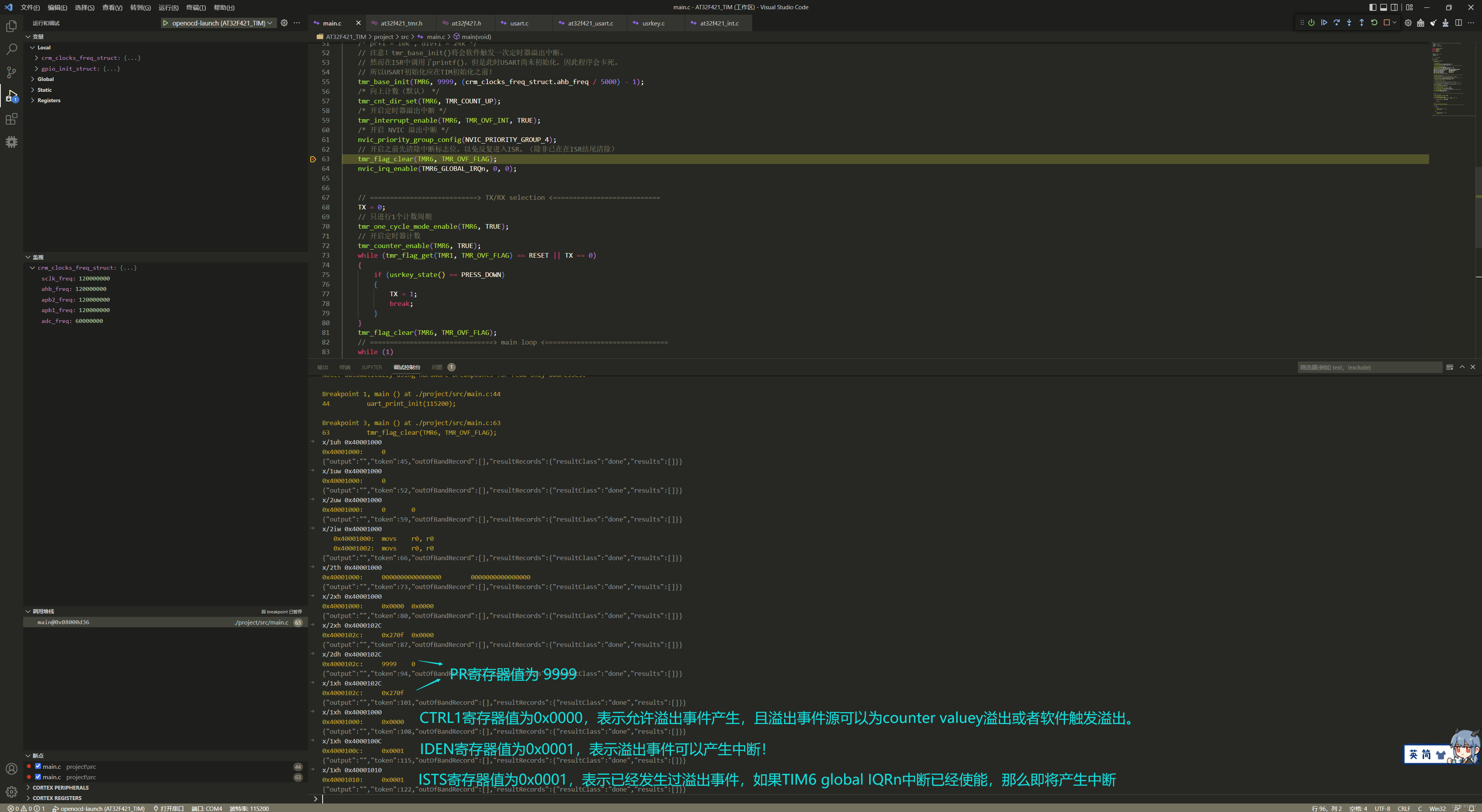
在用GDB调试的过程中查看TMR6的寄存器:
单步一次: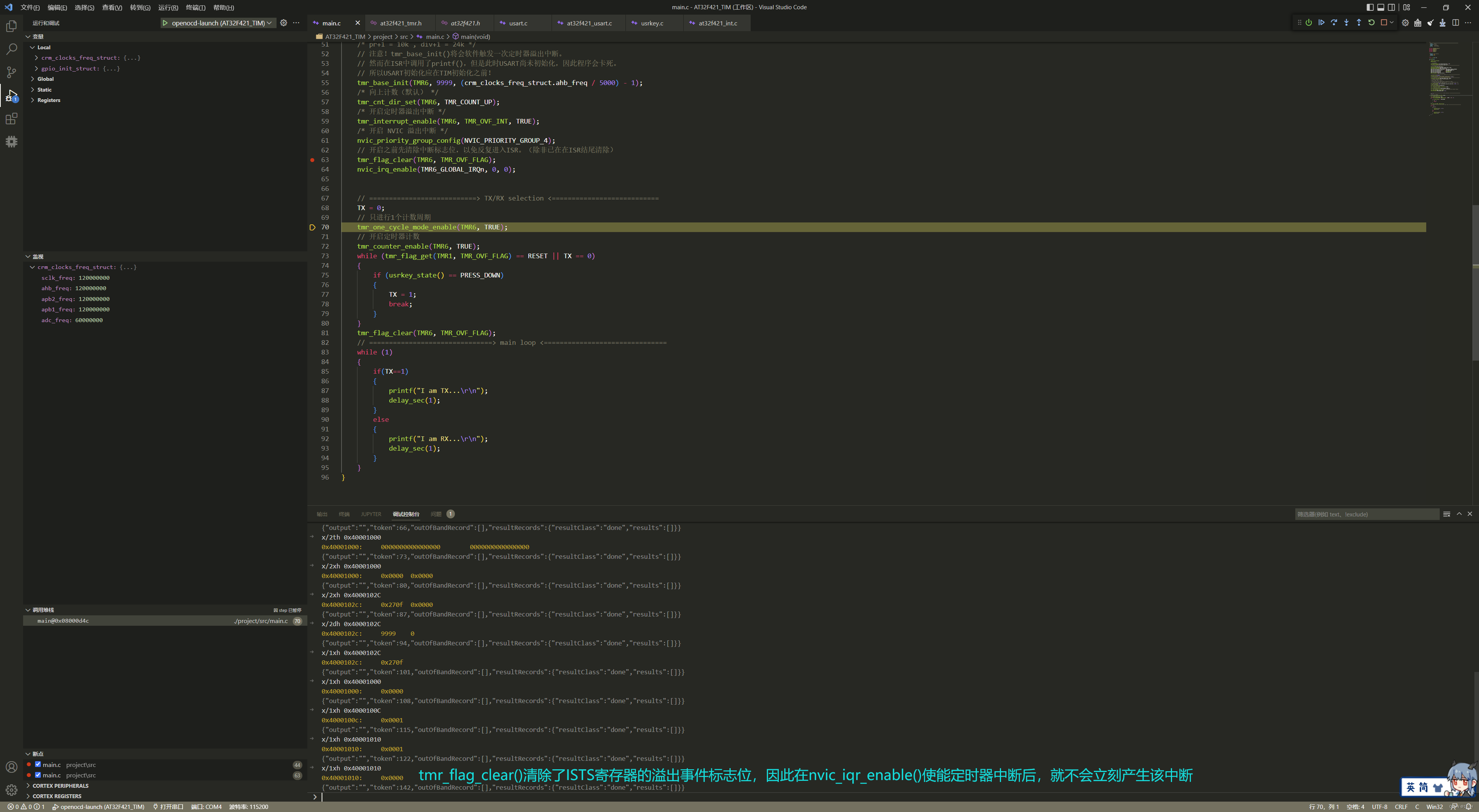
无法解释的问题?
复杂的定时器一次可以产生多个中断,在产生PWM波的过程中发现,溢出中断OVF可以在IDEN寄存器bit 0 置0时(即禁止产生溢出中断)时发生。其他通道也是,明明没有使能对应的中断,却可以触发中断。
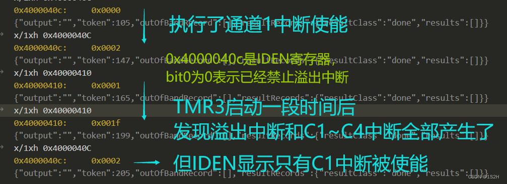
其中
0x4000040c是IDEN,指示哪些中断被使能或禁止。
0x40000410是ISTS,指示当前所有的中断标志。bit[4:0]分别为C4 C3 C2 C1 OVF的中断标志。
(TMR3在初始化 pr 的时候会软件触发一次溢出中断来把pr置入它的影子寄存器。所以TMR3在初始化完成后、开启之前,ISTS 为 0x0001,这是正常的。但后面就不正常了)
我不理解 .JPG


 7975
7975

 被折叠的 条评论
为什么被折叠?
被折叠的 条评论
为什么被折叠?
 到【灌水乐园】发言


