


文章目录
前言
本篇文章将讲解如何使用I2C总线设备驱动模型编写AT24C02驱动程序。
一、I2C总线设备驱动模型
I2C设备模型驱动程序是一种新的I2C设备驱动模型,引入了设备树(Device Tree)这一机制,可以在I2C设备和相应的Linux设备节点之间建立关联。在I2C设备模型中,所有I2C设备节点共用一个I2C设备模型驱动程序,不需要为每个I2C设备节点编写独立的设备驱动程序。
下图来自百问网:
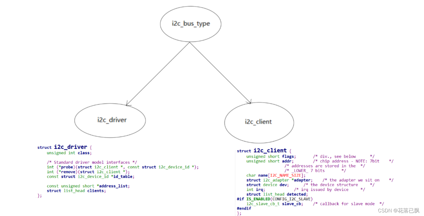
在i2c总线下分别有i2c_client和i2c_driver。i2c_client就是硬件设备(比如本篇文章用到的AT24C02),i2c_driver就是我们需要编写的驱动程序。
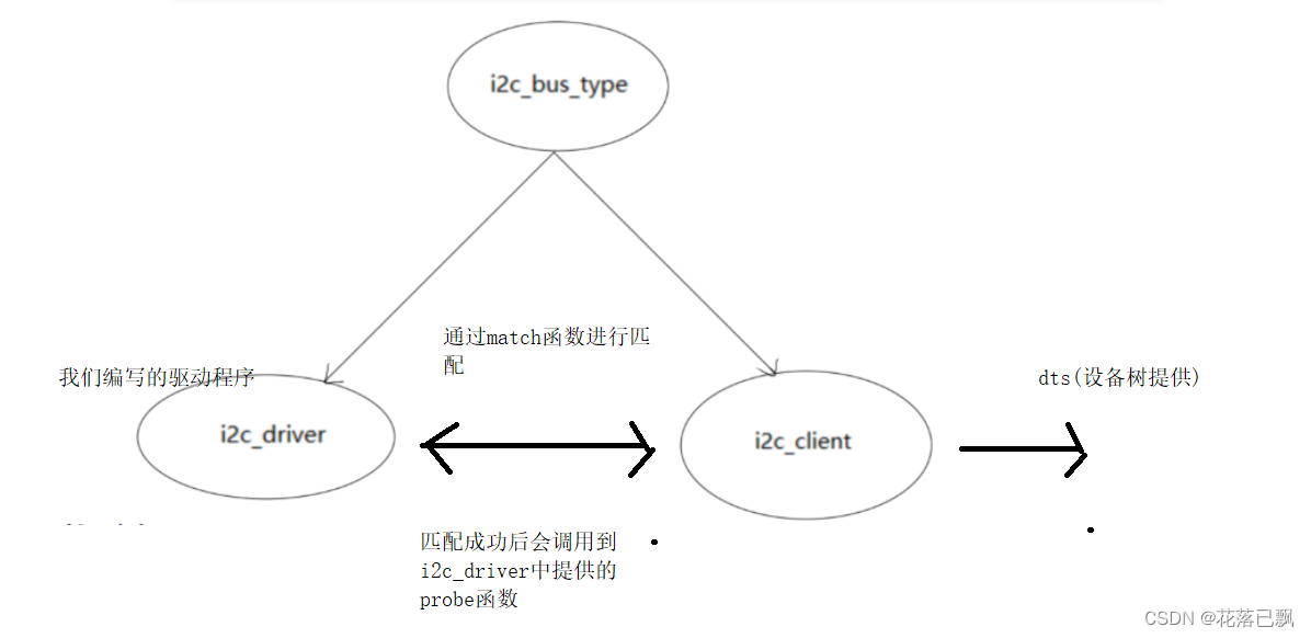
i2c_client由设备树提供。
i2c_driver是我们自己编写的驱动程序,里面提供了probe函数,当驱动和设备树中的compatible属性匹配后调用probe函数。
二、设备树编写
因为我使用的AT24C02是挂载在i2c1这根总线上的所有需要在i2c1这个节点下添加at24c02这个子节点。
reg属性代表的是AT24C02的设备地址。
&i2c1 {
    clock-frequency = <100000>;
    pinctrl-names = "default";
    pinctrl-0 = <&pinctrl_i2c1>;
    status = "okay";

        at24c02 {
                compatible = "my,at24c02";
                reg = <0x50>;
        };
};
三、驱动程序编写
1.提供i2c_driver结构体变量并且注册
这里和之前编写的驱动程序的思路都是一样的提供一个driver结构体变量并且将其注册。
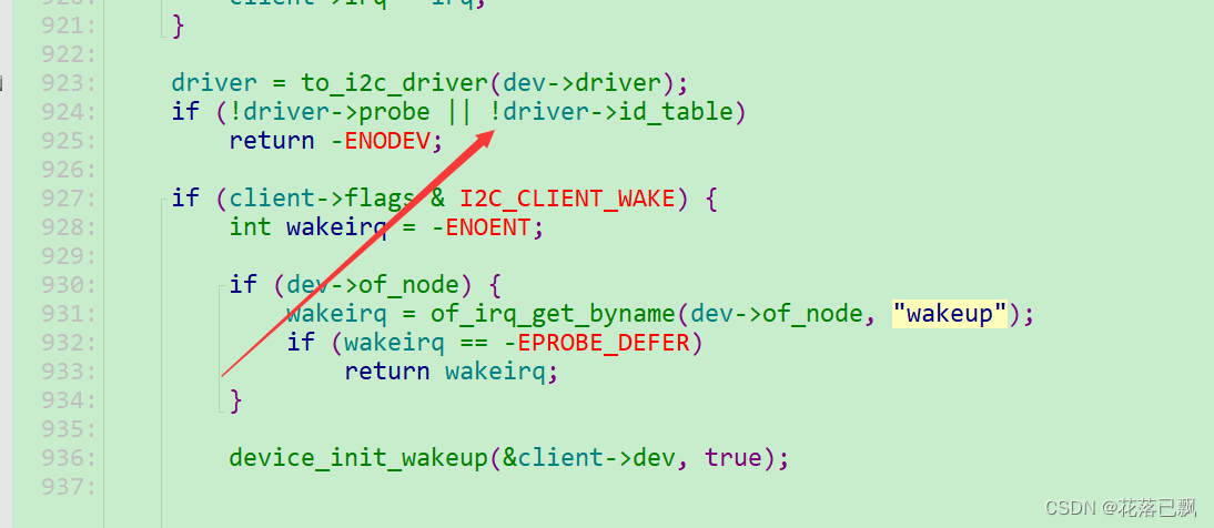
这里和之前最大的不同就是需要在i2c_driver结构体变量中提供id_table成员。
在内核源码中发现缺少了probe函数或者缺少了id_table成员都是无法进行正确的匹配的。
static const struct of_device_id at24c02_of_match[] = {
	{.compatible = "my,at24c02"},
	{}
};


static const struct i2c_device_id at24c02_ids[] = {
	{ "xxxxyyy",	(kernel_ulong_t)NULL },
	{ /* END OF LIST */ }
};


static struct i2c_driver at24c02_drv = {
	.driver = {
		.name = "myat24c02",
		.of_match_table = at24c02_of_match,
	},
	.probe = at24c02_probe,
	.remove = at24c02_remove,
	.id_table = at24c02_ids,
};


/* 2. 在入口函数注册platform_driver */
static int __init at24c02_init(void)
{
    int err;

	printk("%s %s line %d\n", __FILE__, __FUNCTION__, __LINE__);

    return i2c_add_driver(&at24c02_drv);

	return err;
}

/* 3. 有入口函数就应该有出口函数:卸载驱动程序时,就会去调用这个出口函数
 *     卸载platform_driver
 */
static void __exit at24c02_exit(void)
{
	printk("%s %s line %d\n", __FILE__, __FUNCTION__, __LINE__);

    i2c_del_driver(&at24c02_drv);
}


/* 7. 其他完善:提供设备信息,自动创建设备节点                                     */


module_init(at24c02_init);
module_exit(at24c02_exit);

MODULE_LICENSE("GPL");
2.注册file_operations结构体
这里我们使用ioctl来操作AT24C02,ioctl既可以读又可以写,可以对read和write函数进行替换。
/* 定义自己的file_operations结构体                                              */
static struct file_operations at24c02_fops = {
	.owner	 = THIS_MODULE,
	.unlocked_ioctl    = at24c02_chrdev_ioctl,
};

static int at24c02_probe(struct i2c_client *client, const struct i2c_device_id *id)
{
	printk("%s %s line %d\n", __FILE__, __FUNCTION__, __LINE__);
	at24c02_client = client;

	/* 注册file_operations 	*/
	major = register_chrdev(0, "100ask_at24c02", &at24c02_fops);  /* /dev/at24c02 */

	at24c02_class = class_create(THIS_MODULE, "100ask_at24c02_class");
	if (IS_ERR(at24c02_class)) {
		printk("%s %s line %d\n", __FILE__, __FUNCTION__, __LINE__);
		unregister_chrdev(major, "100ask_at24c02");
		return PTR_ERR(at24c02_class);
	}

	device_create(at24c02_class, NULL, MKDEV(major, 0), NULL, "100ask_at24c02"); /* /dev/100ask_at24c02 */

	return 0;
}

static int at24c02_remove(struct i2c_client *client)
{
	printk("%s %s line %d\n", __FILE__, __FUNCTION__, __LINE__);

	device_destroy(at24c02_class, MKDEV(major, 0));
	class_destroy(at24c02_class);
	unregister_chrdev(major, "100ask_at24c02");

	return 0;
}
3.操作AT24C02
根据AT24C02的数据手册我们可以清楚的知道如何去读写AT24C02。
写AT24C02时序:
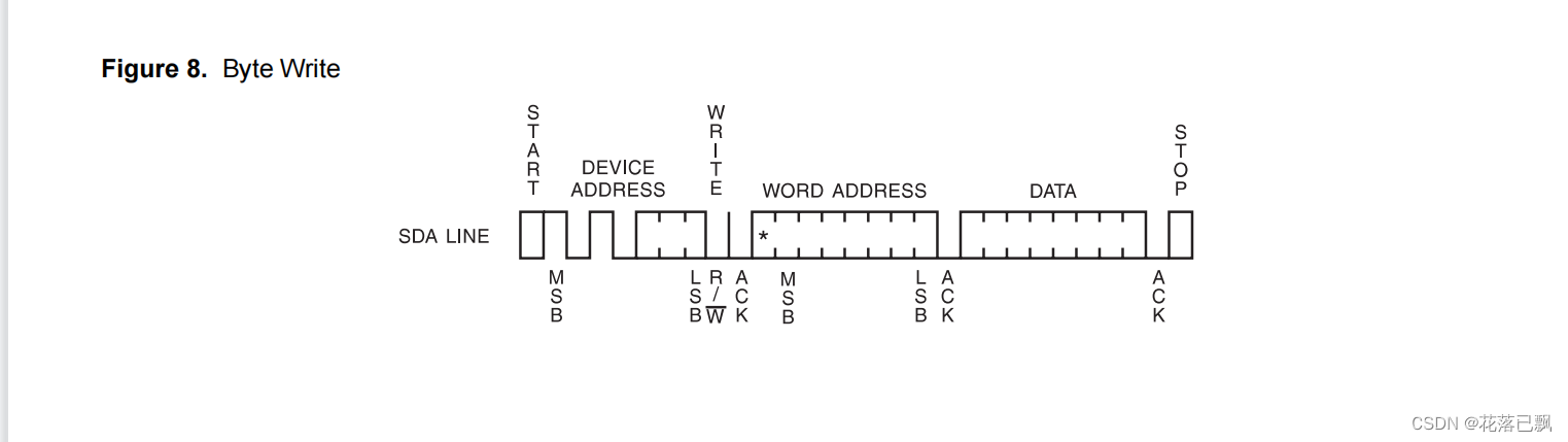
写AT24C02时需要发送设备地址和需要写入的数据,写入数据的地址,只需要构造一个msg消息即可。
读AT24C02时序:
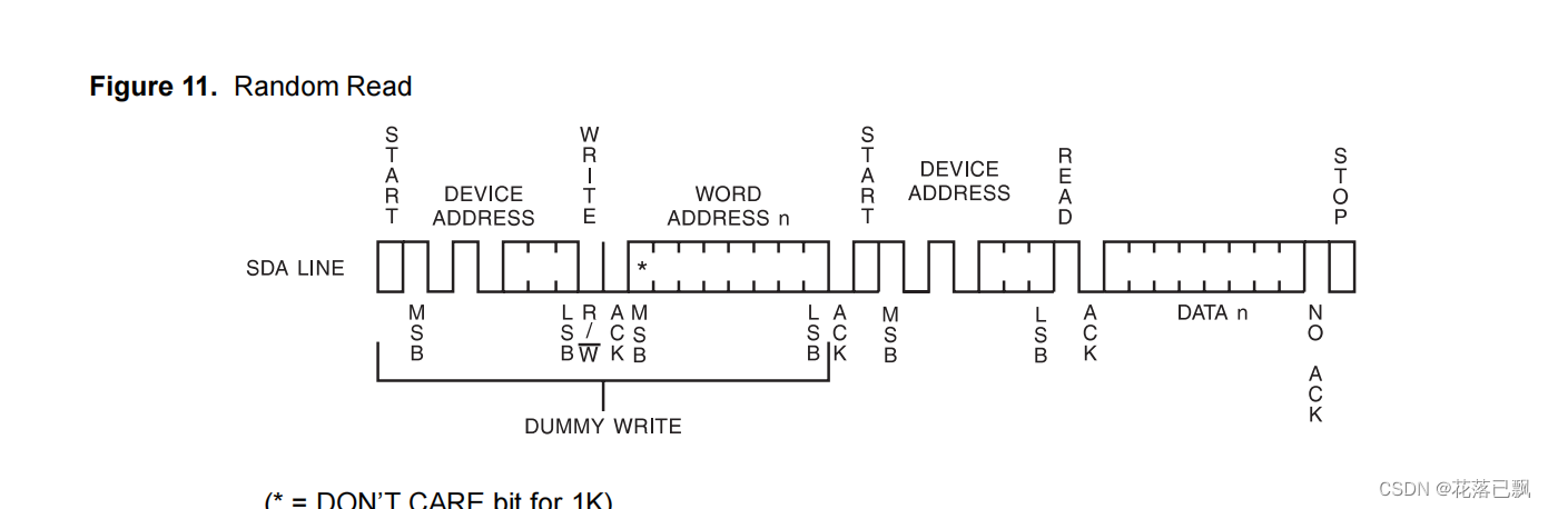
读AT24C02时首先需要写入设备地址,再去读取指定要读取数据的地址。 然后再发起一次操作,指定设备地址,指定读取数据保存的地址。一共需要构造两个msg消息。
#define IOC_AT24C02_READ  100
#define IOC_AT24C02_WRITE 101

/* 主设备号                                                                 */
static int major = 0;
static struct class *at24c02_class;
struct i2c_client *at24c02_client;


static long at24c02_chrdev_ioctl(struct file *file, unsigned int cmd, unsigned long arg)
{
	unsigned char addr;
	unsigned char data;
	unsigned int ker_buf[2];
	unsigned int *usr_buf = (unsigned int *)arg;
	unsigned char byte_buf[2];

	struct i2c_msg msgs[2];

	copy_from_user(ker_buf, usr_buf, 8);

	addr = ker_buf[0];

	switch (cmd)
	{
		case IOC_AT24C02_READ:
		{
			/* 读AT24C02 */
			msgs[0].addr  = at24c02_client->addr;
			msgs[0].flags = 0; /* 写 */
			msgs[0].len   = 1;
			msgs[0].buf   = &addr;

			msgs[1].addr  = at24c02_client->addr;
			msgs[1].flags = I2C_M_RD; /* 读 */
			msgs[1].len   = 1;
			msgs[1].buf   = &data;

			i2c_transfer(at24c02_client->adapter, msgs, 2);

			ker_buf[1] = data;
			copy_to_user(usr_buf, ker_buf, 8);

			break;
		}
		case IOC_AT24C02_WRITE:
		{
			/* 写AT24C02 */
			byte_buf[0] = addr;
			byte_buf[1] = ker_buf[1];

			msgs[0].addr  = at24c02_client->addr;
			msgs[0].flags = 0; /* 写 */
			msgs[0].len   = 2;
			msgs[0].buf   = byte_buf;

			i2c_transfer(at24c02_client->adapter, msgs, 1);

			mdelay(20);

			break;
		}
	}

	return 0;

}
完整代码:
#include <linux/kernel.h>
#include <linux/init.h>
#include <linux/module.h>
#include <linux/slab.h>
#include <linux/delay.h>
#include <linux/mutex.h>
#include <linux/mod_devicetable.h>
#include <linux/log2.h>
#include <linux/bitops.h>
#include <linux/jiffies.h>
#include <linux/of.h>
#include <linux/acpi.h>
#include <linux/i2c.h>
#include <asm/uaccess.h>


#define IOC_AT24C02_READ  100
#define IOC_AT24C02_WRITE 101


/* 主设备号                                                                 */
static int major = 0;
static struct class *at24c02_class;
struct i2c_client *at24c02_client;


static long at24c02_chrdev_ioctl(struct file *file, unsigned int cmd, unsigned long arg)
{


	unsigned char addr;
	unsigned char data;
	unsigned int ker_buf[2];
	unsigned int *usr_buf = (unsigned int *)arg;
	unsigned char byte_buf[2];

	struct i2c_msg msgs[2];

	copy_from_user(ker_buf, usr_buf, 8);

	addr = ker_buf[0];

	switch (cmd)
	{
		case IOC_AT24C02_READ:
		{
			/* 读AT24C02 */
			msgs[0].addr  = at24c02_client->addr;
			msgs[0].flags = 0; /* 写 */
			msgs[0].len   = 1;
			msgs[0].buf   = &addr;

			msgs[1].addr  = at24c02_client->addr;
			msgs[1].flags = I2C_M_RD; /* 读 */
			msgs[1].len   = 1;
			msgs[1].buf   = &data;

			i2c_transfer(at24c02_client->adapter, msgs, 2);

			ker_buf[1] = data;
			copy_to_user(usr_buf, ker_buf, 8);

			break;
		}
		case IOC_AT24C02_WRITE:
		{
			/* 写AT24C02 */
			byte_buf[0] = addr;
			byte_buf[1] = ker_buf[1];

			msgs[0].addr  = at24c02_client->addr;
			msgs[0].flags = 0; /* 写 */
			msgs[0].len   = 2;
			msgs[0].buf   = byte_buf;

			i2c_transfer(at24c02_client->adapter, msgs, 1);

			mdelay(20);

			break;
		}
	}

	return 0;

}


/* 定义自己的file_operations结构体                                              */
static struct file_operations at24c02_fops = {
	.owner	 = THIS_MODULE,
	.unlocked_ioctl    = at24c02_chrdev_ioctl,
};


static int at24c02_probe(struct i2c_client *client, const struct i2c_device_id *id)
{
	printk("%s %s line %d\n", __FILE__, __FUNCTION__, __LINE__);
	at24c02_client = client;

	/* 注册file_operations 	*/
	major = register_chrdev(0, "100ask_at24c02", &at24c02_fops);  /* /dev/at24c02 */

	at24c02_class = class_create(THIS_MODULE, "100ask_at24c02_class");
	if (IS_ERR(at24c02_class)) {
		printk("%s %s line %d\n", __FILE__, __FUNCTION__, __LINE__);
		unregister_chrdev(major, "100ask_at24c02");
		return PTR_ERR(at24c02_class);
	}

	device_create(at24c02_class, NULL, MKDEV(major, 0), NULL, "100ask_at24c02"); /* /dev/100ask_at24c02 */

	return 0;
}

static int at24c02_remove(struct i2c_client *client)
{
	printk("%s %s line %d\n", __FILE__, __FUNCTION__, __LINE__);

	device_destroy(at24c02_class, MKDEV(major, 0));
	class_destroy(at24c02_class);
	unregister_chrdev(major, "100ask_at24c02");

	return 0;
}

static const struct of_device_id at24c02_of_match[] = {
	{.compatible = "my,at24c02"},
	{}
};


static const struct i2c_device_id at24c02_ids[] = {
	{ "xxxxyyy",	(kernel_ulong_t)NULL },
	{ /* END OF LIST */ }
};


static struct i2c_driver at24c02_drv = {
	.driver = {
		.name = "myat24c02",
		.of_match_table = at24c02_of_match,
	},
	.probe = at24c02_probe,
	.remove = at24c02_remove,
	.id_table = at24c02_ids,
};


/* 2. 在入口函数注册platform_driver */
static int __init at24c02_init(void)
{
    int err;

	printk("%s %s line %d\n", __FILE__, __FUNCTION__, __LINE__);

    return i2c_add_driver(&at24c02_drv);

	return err;
}

/* 3. 有入口函数就应该有出口函数:卸载驱动程序时,就会去调用这个出口函数
 *     卸载platform_driver
 */
static void __exit at24c02_exit(void)
{
	printk("%s %s line %d\n", __FILE__, __FUNCTION__, __LINE__);

    i2c_del_driver(&at24c02_drv);
}


/* 7. 其他完善:提供设备信息,自动创建设备节点                                     */


module_init(at24c02_init);
module_exit(at24c02_exit);

MODULE_LICENSE("GPL");
四、应用程序编写
#include <stdlib.h>
#include <stdio.h>
#include <sys/types.h>
#include <sys/stat.h>
#include <fcntl.h>
#include <sys/ioctl.h>


#define IOC_AT24C02_READ  100
#define IOC_AT24C02_WRITE 101


/*
 * at24c02_test /dev/myat24c02 r 10
 * at24c02_test /dev/myat24c02 w 10 123
 */

int main(int argc, char **argv)
{
	int fd;
	int buf[2];

	if ((argc != 4) && (argc != 5))
	{
		printf("Usage: %s <dev> r <addr>\n", argv[0]);
		printf("       %s <dev> w <addr> <val>\n", argv[0]);
		return -1;
	}

	fd = open(argv[1], O_RDWR);
	if (fd < 0)
	{
		printf(" can not open %s\n", argv[1]);
		return -1;
	}

	if (argv[2][0] == 'r')
	{
		buf[0] = strtoul(argv[3], NULL, 0);
		ioctl(fd, IOC_AT24C02_READ, buf);
		printf("Read addr 0x%x, get data 0x%x\n", buf[0], buf[1]);
	}
	else
	{
		buf[0] = strtoul(argv[3], NULL, 0);
		buf[1] = strtoul(argv[4], NULL, 0);
		ioctl(fd, IOC_AT24C02_WRITE, buf);
	}

	return 0;
}
五、上机测试
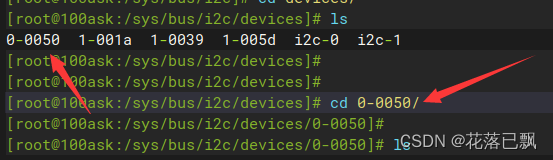
装载驱动后进入/sys/bus/i2c/devices目录下找到我们自己编写的驱动程序:
进入0-0050目录使用cat命令查看具体信息:
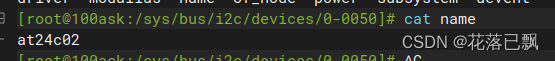
根据信息可以得知驱动程序装载成功。
进行at24c02的读写操作:
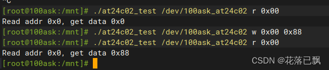
读写测试通过。
总结
本篇文章主要讲解了i2C总线设备驱动模型编写AT24C02驱动程序,这里大家主要需要掌握的就是i2C总线设备驱动这个模型,只要掌握好了这个模型那么剩下的就是裸机的操作了。


 1万+
1万+


 被折叠的 条评论
为什么被折叠?
被折叠的 条评论
为什么被折叠?
 到【灌水乐园】发言


