


1:SW1配置VLAN、VRRP、DHCP,SW1为主网关
[sw1]vlan 2
[sw1-vlan2]quit
[sw1]vlan 3
[sw1-vlan3]quit
[sw1]interface Vlanif 1
[sw1-Vlanif1]ip address 172.16.0.65 27
[sw1-Vlanif1]vrrp vrid 1 virtual-ip 172.16.0.66
[sw1-Vlanif1]vrrp vrid 1 priority 120
[sw1-Vlanif1]vrrp vrid 1 preempt-mode timer delay 20
[sw1-Vlanif1]vrrp vrid 1 track interface GigabitEthernet 0/0/1 reduced 30
[sw1-Vlanif1]
[sw1-Vlanif1]quit
[sw1]dhcp enable
[sw1]ip pool 1
[sw1-ip-pool-1]network 172.16.0.64 mask 27
[sw1-ip-pool-1]gateway-list  172.16.0.66
[sw1-ip-pool-1]dns-list 8.8.8.8
[sw1-ip-pool-1]quit
[sw1]interface Vlanif 1
[sw1-Vlanif1]dhcp select global
[sw1-Vlanif1]quit
[sw1]
[sw1]interface Vlanif 2
[sw1-Vlanif2]ip add
[sw1-Vlanif2]ip address 172.16.0.97 27
[sw1-Vlanif2]vrrp vrid 2 virtual-ip 172.16.0.98
[sw1-Vlanif2]vrrp vrid 2 priority 120
[sw1-Vlanif2]vrrp vrid 2 preempt-mode timer delay 20
[sw1-Vlanif2]vrrp vrid 2 track interface GigabitEthernet 0/0/1 reduced 30
[sw1-Vlanif2]quit
[sw1]ip pool 2
[sw1-ip-pool-2]network 172.16.0.96 mask 27
[sw1-ip-pool-2]gateway-list  172.16.0.98
[sw1-ip-pool-2]dns-list 8.8.8.8
[sw1-ip-pool-2]quit
[sw1]
[sw1]interface Vlanif 2
[sw1-Vlanif2]dhcp select global
[sw1-Vlanif2]quit
[sw1]interface Vlanif 3
[sw1-Vlanif3]ip address 172.16.0.129 27
[sw1-Vlanif3]vrrp vrid 3 virtual-ip 172.16.0.130
[sw1-Vlanif3]vrrp vrid 3 priority 120
[sw1-Vlanif3]vrrp vrid 3 preempt-mode timer delay 20
[sw1-Vlanif3]vrrp vrid 3 track interface GigabitEthernet 0/0/1 reduced 30
[sw1-Vlanif3]quit
[sw1]ip pool 3
[sw1-ip-pool-3]network 172.16.0.128 mask 27
[sw1-ip-pool-3]gateway-list 172.16.0.130
[sw1-ip-pool-3]dns-list 8.8.8.8
[sw1-ip-pool-3]quit
[sw1]interface Vlanif 3
[sw1-Vlanif3]dhcp select global
[sw1-Vlanif3]quit
[sw1]interface GigabitEthernet 0/0/4
[sw1-GigabitEthernet0/0/4]port hybrid tagged vlan 1 to 3
[sw1-GigabitEthernet0/0/4]quit
[sw1]interface GigabitEthernet 0/0/5
[sw1-GigabitEthernet0/0/5]port hybrid tagged vlan 1 to 3
[sw1-GigabitEthernet0/0/5]quit
2: SW2作为备份网关,配置VLAN、VRRP、DHCP
[sw2]vlan 2
[sw2-vlan2]quit
[sw2]vlan 3
[sw2-vlan3]quit
[sw2]interface Vlanif 1
[sw2-Vlanif1]ip address 172.16.0.67 27
[sw2-Vlanif1]vrrp vrid 1 virtual-ip 172.16.0.66
[sw2-Vlanif1]quit
[sw2]dhcp enable
[sw2]ip pool 1
[sw2-ip-pool-1]network 172.16.0.64 mask 27
[sw2-ip-pool-1]gateway-list 172.16.0.66
[sw2-ip-pool-1]dns-list 8.8.8.8
[sw2-ip-pool-1]quit
[sw2]interface Vlanif 1
[sw2-Vlanif1]dhcp select global
[sw2-Vlanif1]quit
[sw2]
[sw2]interface Vlanif 2
[sw2-Vlanif2]ip address 172.16.0.99 27
[sw2-Vlanif2]vrrp vrid 2 virtual-ip 172.16.0.98
[sw2-Vlanif2]quit
[sw2]ip pool 2
[sw2-ip-pool-2]network 172.16.0.96 mask 27
[sw2-ip-pool-2]gateway-list 172.16.0.98
[sw2-ip-pool-2]dns-list 8.8.8.8
[sw2-ip-pool-2]quit
[sw2]interface Vlanif 2
[sw2-Vlanif2]dhcp select global
[sw2-Vlanif2]quit
[sw2]
[sw2]interface Vlanif 3
[sw2-Vlanif3]ip address 172.16.0.131 27
[sw2-Vlanif3]vrrp vrid 3 virtual-ip 172.16.0.130
[sw2-Vlanif3]quit
[sw2]ip pool 3
[sw2-ip-pool-3]network 172.16.0.128 mask 27
[sw2-ip-pool-3]gateway-list  172.16.0.130
[sw2-ip-pool-3]dns-list 8.8.8.8
[sw2-ip-pool-3]quit
[sw2]interface Vlanif 3
[sw2-Vlanif3]dhcp select global
[sw2-Vlanif3]quit
[sw2]interface GigabitEthernet 0/0/5
[sw2-GigabitEthernet0/0/5]port hybrid tagged vlan 1 to 3
[sw2-GigabitEthernet0/0/5]quit
[sw2]interface GigabitEthernet 0/0/4
[sw2-GigabitEthernet0/0/4]port hybrid tagged vlan 1 to 3
[sw2-GigabitEthernet0/0/4]quit
3:SW3配置VLAN
[sw3]interface Eth0/0/1
[sw3-Ethernet0/0/1]port link-type trunk
[sw3-Ethernet0/0/1]port trunk allow-pass vlan 1 to 3
[sw3-Ethernet0/0/1]quit
[sw3]vlan 2
[sw3-vlan2]quit
[sw3]vlan 3
[sw3-vlan3]quit
[sw3]port-group group-member Ethernet 0/0/3 to Ethernet 0/0/5
[sw3-port-group]port link-type access
[sw3-port-group]quit
[sw3]interface Eth0/0/4
[sw3-Ethernet0/0/4]port default vlan 2
[sw3-Ethernet0/0/4]quit
[sw3]interface Eth0/0/5
[sw3-Ethernet0/0/5]port default vlan 3
[sw3-Ethernet0/0/5]quit
[sw3]
[sw3]interface Eth0/0/2
[sw3-Ethernet0/0/2]port link-type trunk
[sw3-Ethernet0/0/2]port trunk allow-pass vlan 1 to 3
[sw3-Ethernet0/0/2]quit
4: SW4配置VLAN
[sw4]interface Eth0/0/1
[sw4-Ethernet0/0/1]port link-type trunk
[sw4-Ethernet0/0/1]port trunk allow-pass vlan 1 to 3
[sw4-Ethernet0/0/1]quit
[sw4]vlan 2
[sw4-vlan2]quit
[sw4]vlan 3
[sw4-vlan3]quit
[sw4]port-group group-member Ethernet 0/0/3 to Ethernet 0/0/4
[sw4-port-group]port link-type access
[sw4-port-group]quit
[sw4]interface Eth0/0/3
[sw4-Ethernet0/0/3]port default vlan 2
[sw4-Ethernet0/0/3]quit
[sw4]interface Eth0/0/4
[sw4-Ethernet0/0/4]port default vlan 3
[sw4-Ethernet0/0/4]quit
[sw4]
[sw4]interface Eth0/0/2
[sw4-Ethernet0/0/2]port link-type trunk
[sw4-Ethernet0/0/2]port trunk allow-pass vlan 1 to 3
[sw4-Ethernet0/0/2]quit
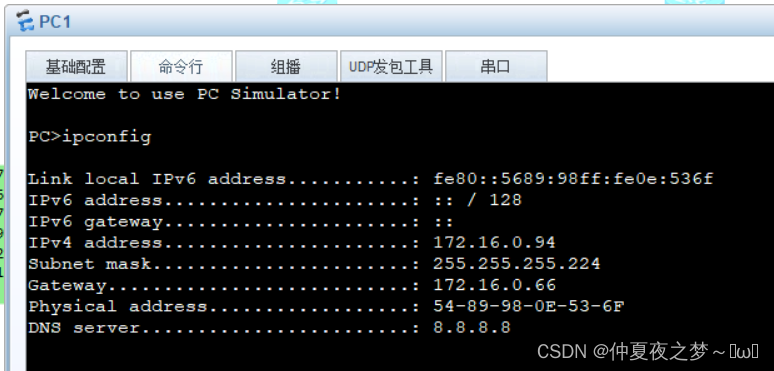
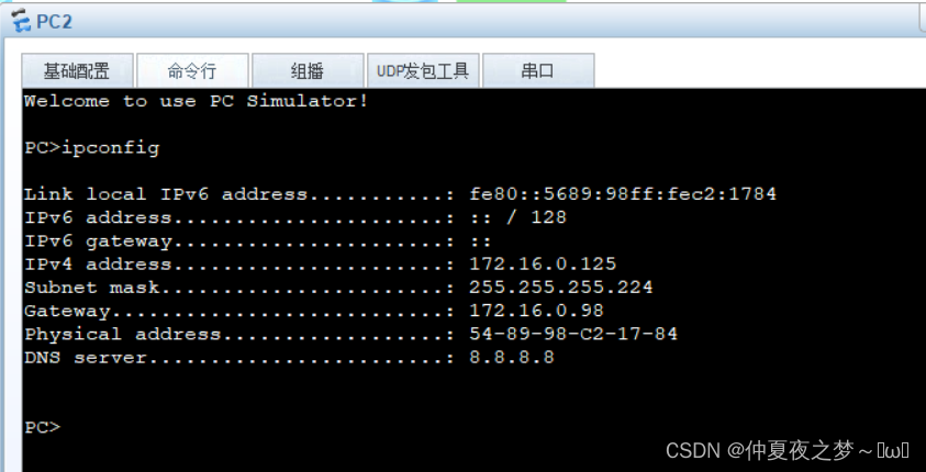
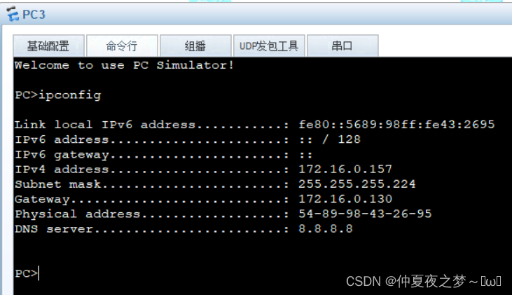
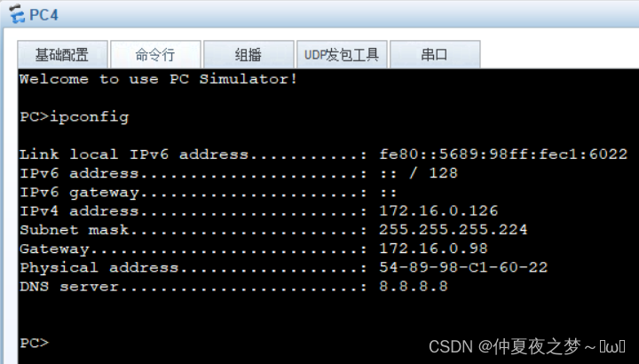
测试所有PC是否将SW1作为网关通过DHCP获取IP
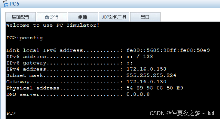
5:SW1与SW2之间做链路叠加eth-trunk
[sw1]interface Eth-Trunk 0
[sw1-Eth-Trunk0]quit
[sw1]interface GigabitEthernet 0/0/2
[sw1-GigabitEthernet0/0/2]eth-trunk 0
[sw1-GigabitEthernet0/0/2]quit
[sw1]interface GigabitEthernet 0/0/3
[sw1-GigabitEthernet0/0/3]eth-trunk 0
[sw1-GigabitEthernet0/0/3]quit
[sw1]interface Eth-Trunk 0
[sw1-Eth-Trunk0]port link-type hybrid
[sw1-Eth-Trunk0]port hybrid tagged vlan 1 to 3
[sw1-Eth-Trunk0]quit
[sw2]interface Eth-Trunk 0
[sw2-Eth-Trunk0]quit
[sw2]interface GigabitEthernet 0/0/2
[sw2-GigabitEthernet0/0/2]eth-trunk 0
[sw2-GigabitEthernet0/0/2]quit
[sw2]interface GigabitEthernet 0/0/3
[sw2-GigabitEthernet0/0/3]eth-trunk 0
[sw2-GigabitEthernet0/0/3]quit
[sw2]interface Eth-Trunk 0
[sw2-Eth-Trunk0]port link-type hybrid
[sw2-Eth-Trunk0]port hybrid tagged vlan 1 to 3
[sw2-Eth-Trunk0]quit
6:配置MSTP,VLAN1划入实例1,VLAN2、3划入实例2,主根为SW1,备份根为SW2
[sw1]stp mode mstp
[sw1]stp enable
[sw1]stp region-configuration
[sw1-mst-region]region-name a
[sw1-mst-region]instance 1 vlan 1
[sw1-mst-region]instance 2 vlan 2 to 3
[sw1-mst-region]active region-configuration
[sw1-mst-region]quit
[sw1]stp instance 1 root primary
[sw1]stp instance 2 root  primary
[sw2]stp mode mstp
[sw2]stp enable
[sw2]stp region-configuration
[sw2-mst-region]region-name a
[sw2-mst-region]instance 1 vlan 1
[sw2-mst-region]instance 2 vlan 2 to 3
[sw2-mst-region]active region-configuration
[sw2-mst-region]quit
[sw2]stp instance 1 root secondary
[sw2]stp instance 2 root secondary
[sw3]stp mode mstp
[sw3]stp enable
[sw3]stp region-configuration
[sw3-mst-region]region-name a
[sw3-mst-region]instance 1 vlan 1
[sw3-mst-region]instance 2 vlan 2 to 3
[sw3-mst-region]active region-configuration
[sw3-mst-region]quit
[sw4]stp mode mstp
[sw4]stp enable
[sw4]stp region-configuration
[sw4-mst-region]region-name a
[sw4-mst-region]instance 1 vlan 1
[sw4-mst-region]instance 2 vlan 2 to 3
[sw4-mst-region]active region-configuration
[sw4-mst-region]quit
7:在SW1和SW2的物理接口配置IP地址,使得它们能正常访问R1。
ensp模拟器上的三层交换机不能直接给物理接口配置IP地址,所以创建一个VLAN并给该VLAN配置IP地址,将配置IP地址的接口改为access模式且划分到一个VLAN中。
[sw1]vlan 10
[sw1-vlan10]quit
[sw1]interface GigabitEthernet 0/0/1
[sw1-GigabitEthernet0/0/1]port link-type access
[sw1-GigabitEthernet0/0/1]port default vlan 10
[sw1-GigabitEthernet0/0/1]quit
[sw1]interface Vlanif 10
[sw1-Vlanif10]ip address 172.16.0.2 27
[sw1-Vlanif10]quit
[sw2]vlan 10
[sw2-vlan10]
[sw2-vlan10]quit
[sw2]interface GigabitEthernet 0/0/1
[sw2-GigabitEthernet0/0/1]port link-type access
[sw2-GigabitEthernet0/0/1]port default vlan 10
[sw2-GigabitEthernet0/0/1]quit
[sw2]interface Vlanif 10
[sw2-Vlanif10]ip address 172.16.0.34 27
[sw2-Vlanif10]quit
[r1]interface GigabitEthernet 0/0/1
[r1-GigabitEthernet0/0/1]ip address 172.16.0.1 27
[r1-GigabitEthernet0/0/1]quit
[r1]interface GigabitEthernet 0/0/2
[r1-GigabitEthernet0/0/2]ip address 172.16.0.33 27
[r1-GigabitEthernet0/0/2]quit
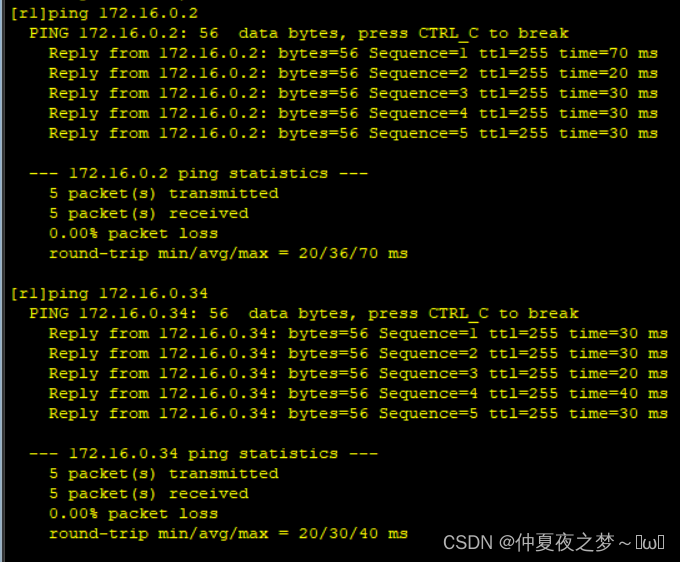
测试r1与SW1和SW2物理接口是否能ping通
8:R1配置VLAN1、2、3的静态路由,下一跳为SW2连接R1接口的路由为备份路由,优先级较大
[r1]ip route-static 172.16.0.64 255.255.255.224 172.16.0.2
[r1]ip route-static 172.16.0.64 255.255.255.224 172.16.0.34 preference 61
[r1]ip route-static 172.16.0.96 255.255.255.224 172.16.0.2
[r1]ip route-static 172.16.0.96 255.255.255.224 172.16.0.34 preference 61
[r1]ip route-static 172.16.0.128 255.255.255.224 172.16.0.2
[r1]ip route-static 172.16.0.128 255.255.255.224 172.16.0.34 preference 61
9: R1和R2配置公网地址,使用NAT实现所有PC访问ISP环回
[r1]interface GigabitEthernet 0/0/0
[r1-GigabitEthernet0/0/0]ip address 12.1.1.1 24
[r1-GigabitEthernet0/0/0]quit
[r1]acl 2000
[r1-acl-basic-2000]rule 5 permit source 172.16.0.0 0.0.0.255
[r1]interface GigabitEthernet 0/0/0
[r1-GigabitEthernet0/0/0]nat outbound 2000
[r1-GigabitEthernet0/0/0]quit
[r1]ip route-static 0.0.0.0 0 12.1.1.2
[r2]interface GigabitEthernet0/0/0
[r2]ip address 12.1.1.2 255.255.255.0
[r2]interface LoopBack0
[r2]ip address 2.2.2.2 255.255.255.0
[sw1]ip route-static 0.0.0.0 0 172.16.0.1
[sw2]ip route-static 0.0.0.0 0 172.16.0.33
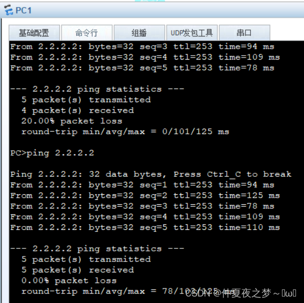
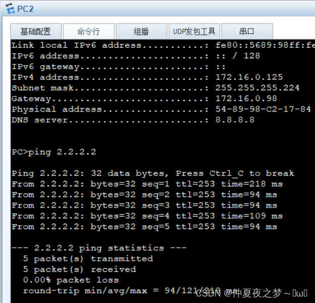
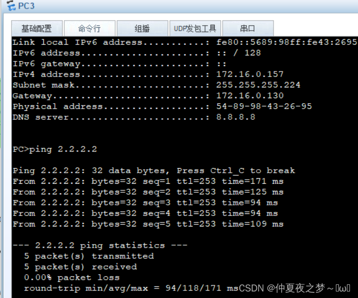
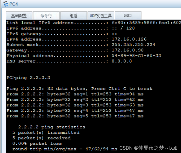
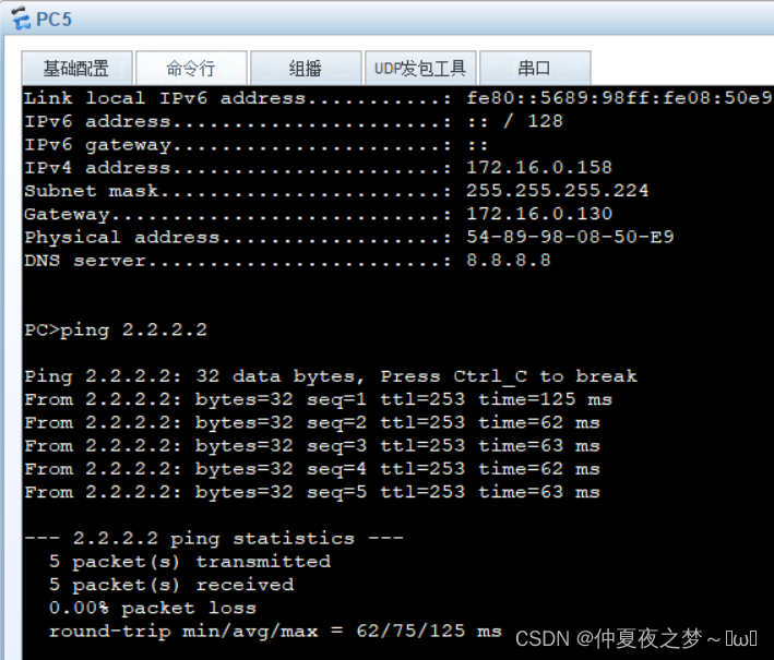
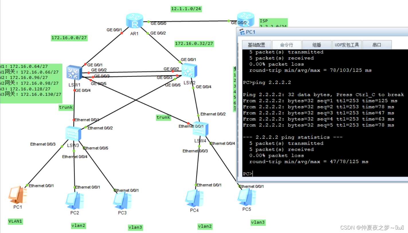
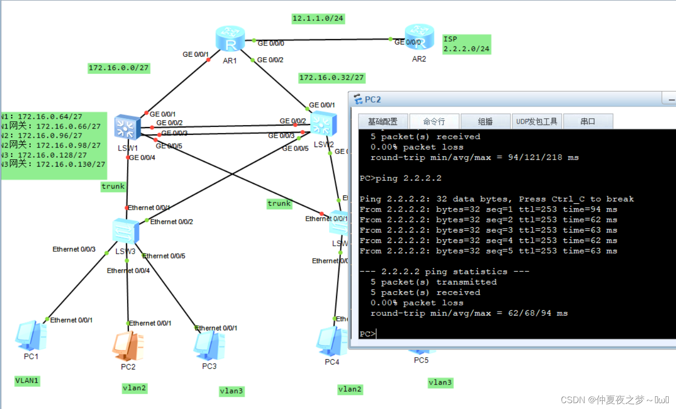
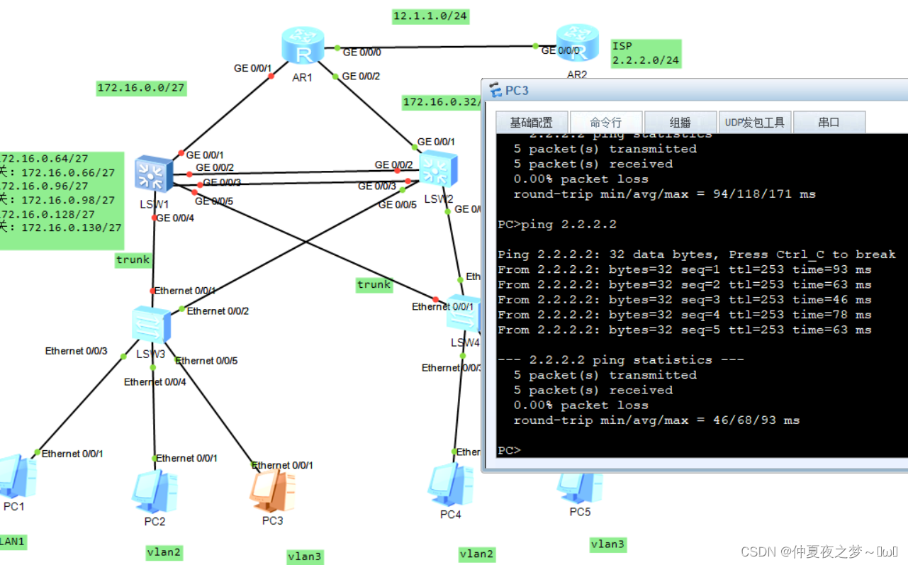
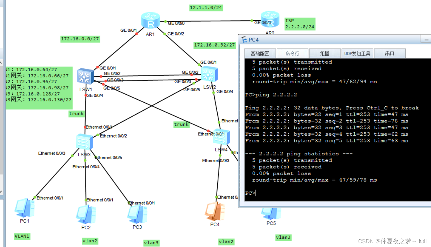
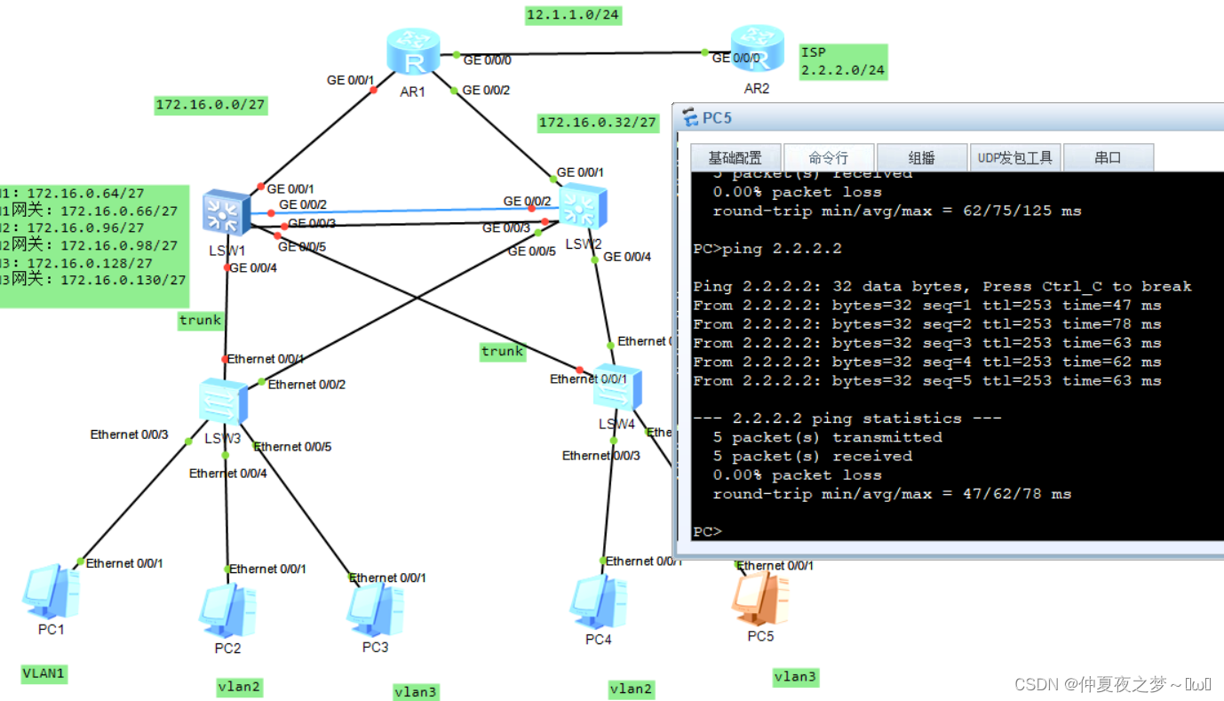
测试所有PC是否能正常访问ISP环回
10:在SW1上开启telnet服务,R1配置端口映射
[sw1]user-interface vty 0 4
[sw1-ui-vty0-4]authentication-mode password
[sw1-ui-vty0-4]user privilege level 15
[sw1-ui-vty0-4]set authentication password simple aaa123
[r1]interface GigabitEthernet 0/0/0
[r1-GigabitEthernet0/0/0]nat server protocol tcp global current-interface telnet
 inside 172.16.0.2 telnet
Warning:The port 23 is well-known port. If you continue it may cause function fa
ilure.
Are you sure to continue?[Y/N]:y
[r1-GigabitEthernet0/0/0]
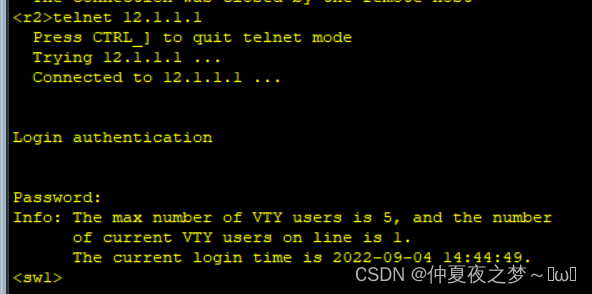
在R2上测试是否能远程登录SW1:
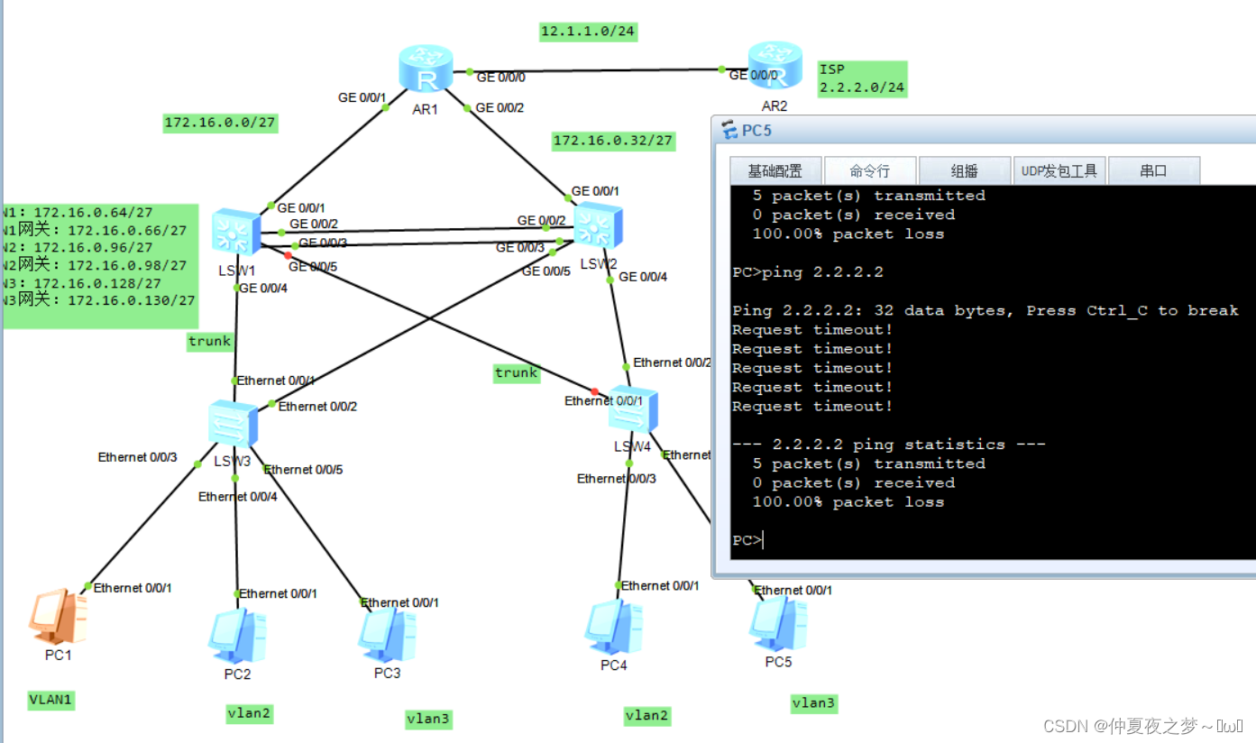
将SW1设备关闭,测试PC是否还能正常访问ISP环回:
MSTP测试:
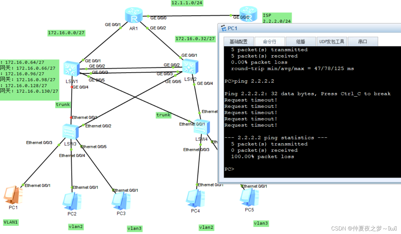
这里出错了,我目前还没有找到出错原因
断开SW2的e0/0/1口,测试PC4、5能否正常访问ISP环回

断开SW1的e0/0/1口,测试PC1能否正常访问ISP环回


 219
219


 被折叠的 条评论
为什么被折叠?
被折叠的 条评论
为什么被折叠?
 到【灌水乐园】发言


