


目录
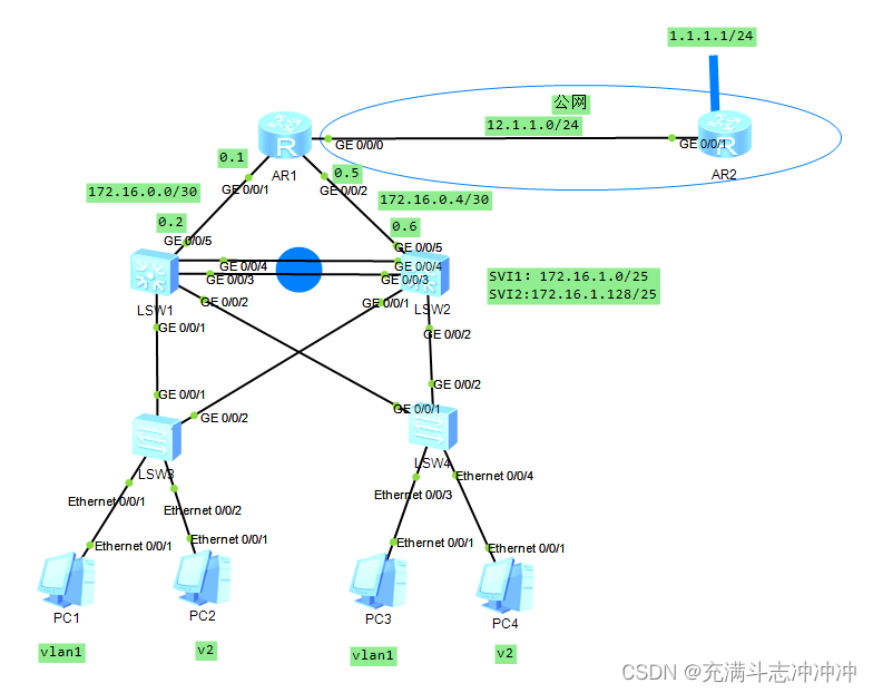
一、实验拓扑
二、实验需求
1、内网IP地址172.16.0.0/16 合理分配
2、SW1/2之间互为备份
3、VRRP/STP/VLAN/TRUNK均使用
4、所有PC通过DHCP获取IP地址
5、内网可以访问外网
三、实验思路
1、在三成交换机上用以太网中继Eth-Trunk(华为)连接多个接口逻辑合并为一个。
2、创建vlan并接口划分vlan,并设置相应的trunk口。
3、使用MSTP将多个vlan放置于一个组内,基于每个组一棵生成树。
4、再创建SVI和VRRP,在网关冗余技术中,ICMP重定向是失效的;故当上行链路DOWN时,网关将不会切换,所有要定义上行链路追踪。
5、在SW1和SW2上都基于虚拟网关配置DHCP池塘。
6、再在路由器和交换机上配置ip地址(因交换机无法配置ip地址,可以在vlan中配置然后绑定接口),然后配置缺省路由和nat。实现全网可达。
四、实验配置
1、创建Eth-Trunk 0
[sw1]interface Eth-Trunk 0  创建通道接口
[sw1-Eth-Trunk0]q
[sw1]interface GigabitEthernet 0/0/3  将物理接口加入到通道内
[sw1-GigabitEthernet0/0/3]eth-trunk 0
[sw1-GigabitEthernet0/0/3]int g0/0/4
[sw1-GigabitEthernet0/0/4]eth-trunk 0


SW2同理
2、创建vlan并接口划分vlan,并设置相应的trunk口。
[SW1]vlan 2
[SW1]port-group group-member g0/0/1 g0/0/2 Eth-Trunk 0
[SW1-port-group]p l t
[SW1-port-group]port trunk allow-pass vlan 2

SW2同理


[SW3]port-group group-member g0/0/1 g0/0/2
[SW3-port-group]p l t
[SW3-port-group]port trunk allow-pass vlan 2
[SW3]int e0/0/2
[SW3-Ethernet0/0/2] port link-type access
[SW3-Ethernet0/0/2] port default vlan 2

SW4同理
3、使用MSTP将多个vlan放置于一个组内,基于每个组一棵生成树。
[SW1]stp mode mstp
[sw1]stp enable
[sw1]stp region-configuration
[sw1-mst-region]region-name a    所有设备应在一个组内
[sw1-mst-region]instance 1 vlan 1
[sw1-mst-region]instance 2 vlan 2
[sw1-mst-region]active region-configuration
[SW1]stp instance 1 root primary
[SW1]stp instance 2 root secondary
组1 的主根,组2 的备份根

SW2同理但是组2 的主根,组1 的备份根
创建组部分代码和SW1同理
[SW2]stp instance 2 root primary
[SW2]stp instance 1 root secondary


SW3和SW4同理创建组a但是都是a组的组员
4、再创建SVI和VRRP,定义上行链路追踪,再启用边缘端口(edged port)功能。
[SW1]int vlan 1
[SW1-Vlanif1] ip address 172.16.1.1 255.255.255.128
[SW1-Vlanif1] vrrp vrid 1 virtual-ip 172.16.1.126  虚拟网关接口
[SW1-Vlanif1] vrrp vrid 1 priority 110
[SW1-Vlanif1] vrrp vrid 1 track interface GigabitEthernet0/0/5 reduced 15 当上链端口断了优先级下降15
[SW1]int vlan 2
[SW1-Vlanif2] ip address 172.16.1.129 255.255.255.128
[SW1-Vlanif2] vrrp vrid 1 virtual-ip 172.16.1.254


[SW2]int vlan 1
[SW2-Vlanif1] ip address 172.16.1.2 255.255.255.128
[SW2-Vlanif1] vrrp vrid 1 virtual-ip 172.16.1.126

[SW2]int vlan 2
[SW2-Vlanif2] ip address 172.16.1.130 255.255.255.128
[SW2-Vlanif2] vrrp vrid 1 virtual-ip 172.16.1.254
[SW2-Vlanif2] vrrp vrid 1 priority 110
[SW2-Vlanif2] vrrp vrid 1 track interface GigabitEthernet0/0/5 reduced 15


[SW3]int e0/0/2
[SW3-Ethernet0/0/2] stp edged-port enable 启用边缘端口(edged port)功能。
SW4同理
5、在SW1和SW2上基于虚拟网关配置DHCP池塘。
[SW1]ip pool v1
[SW1-ip-pool-v1] gateway-list 172.16.1.126
[SW1-ip-pool-v1] network 172.16.1.0 mask 255.255.255.128
[SW1-Vlanif1] dhcp select global
[SW1]ip pool v2
[SW1-ip-pool-v2] gateway-list 172.16.1.254
[SW1-ip-pool-v2] network 172.16.1.128 mask 255.255.255.128
[SW1-Vlanif2] dhcp select global
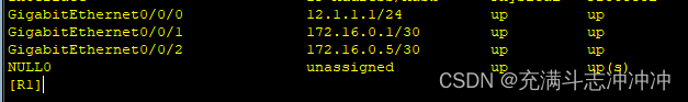
SW2同理6、再在路由器和交换机上配置ip地址,然后配置缺省路由和nat。实现全网可达。
[SW1] vlan 100
[SW1]int vlan 100
[SW1-Vlanif100] ip address 172.16.0.2 255.255.255.252
[SW1]int g0/0/5
[SW1-GigabitEthernet0/0/5] port link-type access
[SW1-GigabitEthernet0/0/5] port default vlan 100

SW2同理
[SW1] ip route-static 0.0.0.0 0.0.0.0 172.16.0.1
[SW2]ip route-static 0.0.0.0 0.0.0.0 172.16.0.5
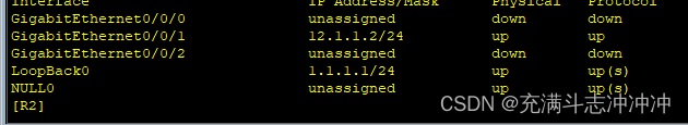
[R1] ip route-static 0.0.0.0 0.0.0.0 12.1.1.2
[R1] ip route-static 172.16.1.0 255.255.255.0 172.16.0.2
[R1] ip route-static 172.16.1.0 255.255.255.0 172.16.0.6
[R1]acl 2000
[R1-acl-basic-2000] rule 5 permit source 172.16.0.0 0.0.255.255
[R1]int g0/0/0
[R1-GigabitEthernet0/0/0] nat outbound 2000
五、测试
测试PC1 ping PC4、3及 R2环回
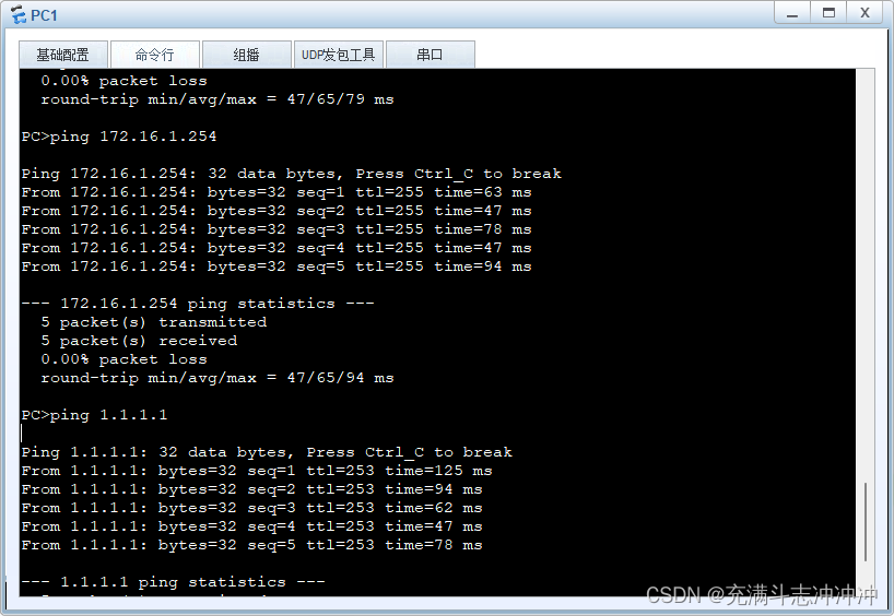
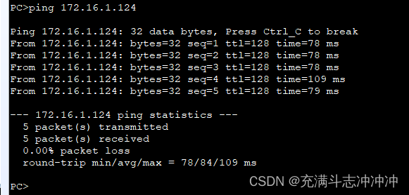
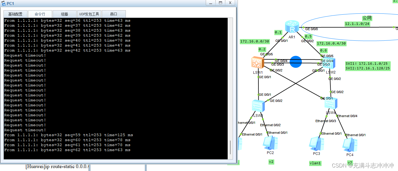
测试PC1ping R2环回将SW1关机再开机,实现备份作用。
关机
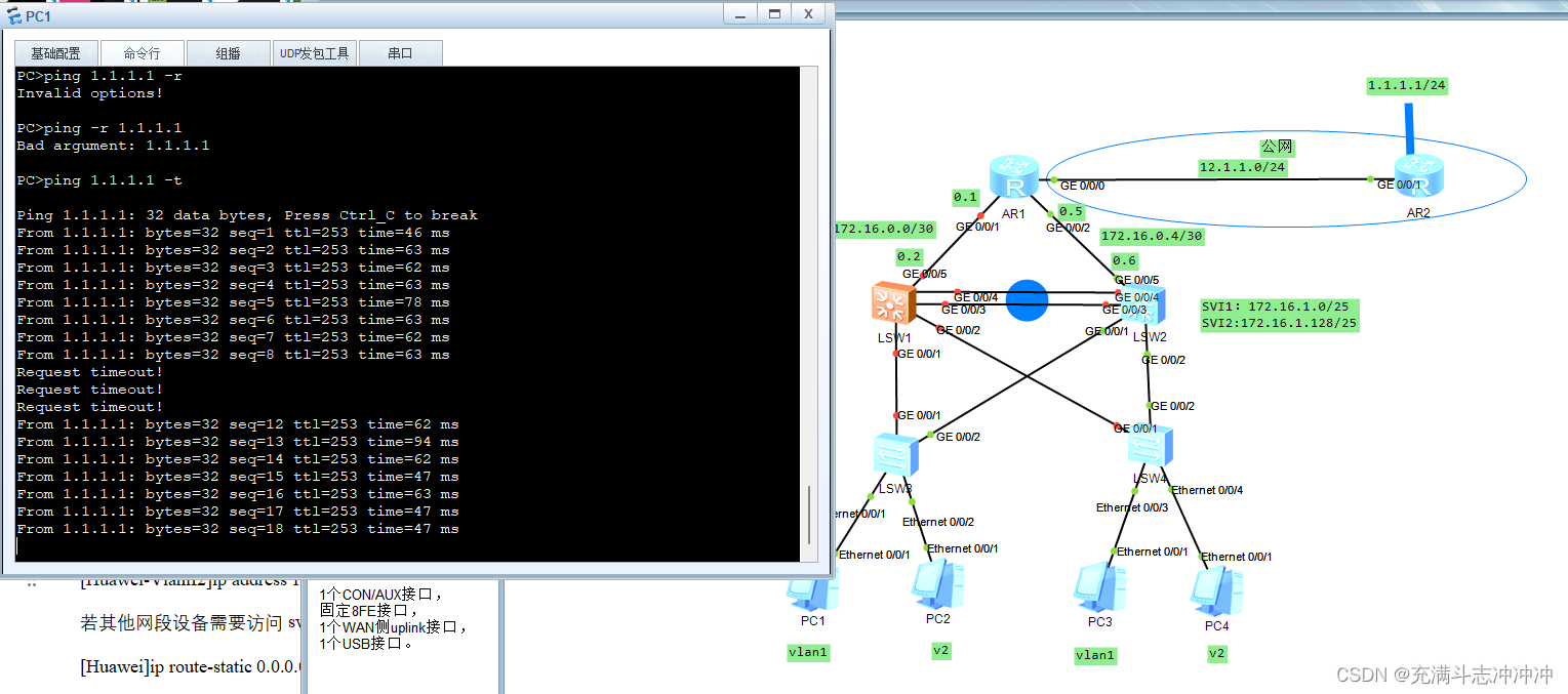
开机


 3万+
3万+

 被折叠的 条评论
为什么被折叠?
被折叠的 条评论
为什么被折叠?
 到【灌水乐园】发言


