


 HI 好久不见!我要来霍霍一下了!
  作为电子发烧友,是不是都想拥有一件趁手的电烙铁?虽然目前市面上有很多款式的电烙铁,但看了看我这捉襟见肘的口袋,还是无法忍痛入手。既然如此,那就奋发图强自供自足吧!网上冲浪了很久觉得T12电烙铁便捷、发热快等实用性挺符合心里预期,这样的话以后出门就不用背着沉甸甸的背包了,关键DIY的成本就很香。
作为电子发烧友,是不是都想拥有一件趁手的电烙铁?虽然目前市面上有很多款式的电烙铁,但看了看我这捉襟见肘的口袋,还是无法忍痛入手。既然如此,那就奋发图强自供自足吧!网上冲浪了很久觉得T12电烙铁便捷、发热快等实用性挺符合心里预期,这样的话以后出门就不用背着沉甸甸的背包了,关键DIY的成本就很香。
前言
一心想要DIY属于自己的专属电烙铁,然后就网上疯狂冲浪冲浪看了很多T12电烙铁的方案,一般都是主控MCU + PD协议芯片实现,总觉得使用两个芯片过于累赘。
最关键的一点是因为我比较铁公鸡~~~。所以在此次T12电烙铁的方案中将使用:WCH的CH32X035,64K flash + PD PHY 是真的香啊!单颗芯片完成PD等快充诱骗还能作为主控MCU控制温度、驱动LED屏幕、检测按键等……
一、方案介绍
1、主控MCU:CH32X035 (产品中心 - 南京沁恒微电子股份有限公司)
CH32X035是基于青稞V4C内核设计的工业级微控制器。CH32X035内置全速USB和USB PD PHY,支持USB Host 主机和USB Device 设备功能、USB PD 及type C 快充功能,内置可编程协议I/O 控制器,提供了2 组OPA 运放、3 组CMP 电压比较器、4 组USART 串口、I2C、SPI、多组定时器、12位ADC、14路Touchkey等丰富外设资源。

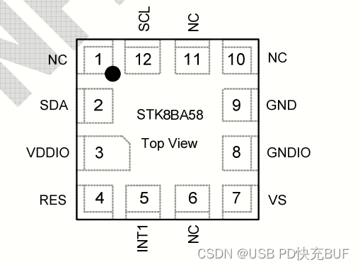
2、加速度传感器(陀螺仪)STK8BA58 (STK8BA58_STK8BA58采购信息-立创电子元器件商城 (szlcsc.com))
STK8BA58是一个+2g/+4g/±8g, 3轴线性加速度计,具有数字输出(I'C)。它是一款低调的电容式MEMS传感器,具有Og偏移和增益误差补偿功能,并以用户可配置的每秒采样率转换为12位数字值。该装置可通过中断引脚安排传感器数据的变化。STK8BA58采用小型2.0mm x 2.0mm x 1.0 mm LGA封装,保证在-40°C至+85°C的扩展温度范围内工作。
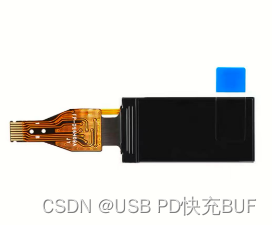
3、TFT显示
CZ0001 「0.96寸彩色TFT显示屏高清IPS LCD裸屏液晶屏分辨率80*160 SPI接口」
(【淘宝】https://m.tb.cn/h.5Mg4xXg?tk=BSzoWTT1tvG CZ0001)
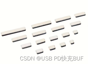
CZ0001 「FFC/FPC连接器插座 间距0.5mm 4/6/8/10/12/14/16-60P 前插后翻盖」
(【淘宝】https://m.tb.cn/h.5oL75os?tk=FfOAWTTXO3k CZ0001 )
4、按键 (TS-KG86EV-ART35F_(HANBO(汉博))TS-KG86EV-ART35F中文资料_价格_PDF手册-立创电子商城 (szlcsc.com))

5、运放 (GS8511_GS8511采购信息-立创电子元器件商城 (szlcsc.com))

二、原理图

注:实测LDO在20V输入的时候发烫严重,目前采用两个LDO并联的方式规避,后期2.0版本将采用DCDC,另外TFT的排座焊接真苦恼,后期考虑使用焊接的形式焊接屏幕。
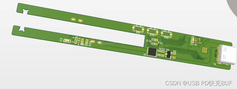
三、PCB
四、代码框架
1.主函数
主函数代码如下(示例):
#include "ch32x035.h"


/*********************************************************************************
* 电源信息
* 休眠温度
* 休眠时间
* 开机加热
* 恢复出厂
*******************************************************************************/


/*********************************************************************
 * @fn      main
 *
 * @brief   Main program.
 *
 * @return  none
 */
int main(void)
{

        SysAppInitial();                                     /*系统APP初始化*/


    while(1)
    {

        TIM_ITConfig( TIM2, TIM_IT_Update , DISABLE );
        Sys_Timer.Tmr_Ms_Dlt = Sys_Timer.Tim_Ms_Cnt - Sys_Timer.Tim_Ms_Cnt_Last;
        Sys_Timer.Tim_Ms_Cnt_Last = Sys_Timer.Tim_Ms_Cnt;
        TIM_ITConfig( TIM2, TIM_IT_Update , ENABLE );


        SysPowerFunction();                   /*系统电源处理函数*/

        SysTemperFunction();                  /*系统T12温度处理函数*/

        SysDisplayFunction();                 /*系统显示函数*/

        SysKeyFunction();                     /*系统ADC检测函数函数*/


    }
}
2.系统APP初始化
代码如下(示例):
void SysAppInitial(void)
{
      NVIC_PriorityGroupConfig(NVIC_PriorityGroup_2);      /*中断向量*/
      SystemCoreClockUpdate();                             /*系统时钟*/
      Delay_Init();                                        /*系统延时*/
      SysGpioInitial();                                    /*GPIO初始化*/
      SysPwmInitial();                                     /*PWM初始化*/
      SysOpaInitial();                                     /*OPA初始化*/
      SysAdcInitial();                                     /*ADC初始化*/
      SysFlashInitial();                                   /*Flash初始化*/
      SysLcdInitial();                                     /*LCD初始化*/
      SysPidIntial();                                      /*PID初始化*/
      SysPdInitial();                                      /*PD初始化*/
      memset(&Sys_Ctrl,0,sizeof(Sys_Ctrl));
}
3.系统电源处理函数
代码如下(示例):
/*********************************************************************
 *  系统电源处理函数
 ********************************************************************/
void SysPowerFunction(void)
{
    switch( PD_Ctrl.STA)            /*系统电源状态机*/
    {
  /**********************初始未检测电源连接*****************************/
      case Sta_DisConnect:
          switch(Get_CC_Status())
          {
            case 1:
                USBPD->CONFIG &= ~CC_SEL;
                PD_Ctrl.STA = Sta_SrcConnect;                        /*设置PD状态为SRC接入*/
              break;
            case 2:
                USBPD->CONFIG |= CC_SEL;
                PD_Ctrl.STA = Sta_SrcConnect;                        /*设置PD状态为SRC接入*/
              break;
            case 3:
                PD_Ctrl.STA = Sta_LeiSure;
              break;
          }
          SysTimerInitial();                                     /*1ms进入一次*/
               break;
 /**********************PD充电器连接检测*****************************/
      case Sta_SrcConnect:

           PD_Recvd_Message();                                    /*PD设置为接收模式*/
           NVIC_EnableIRQ( USBPD_IRQn );                          /*使能PD中断*/
           PD_Ctrl.STA = Sta_Wait_Rx_SrcCap;
               break;
/**********************等待充电器SrcCap*****************************/
      case Sta_Wait_Rx_SrcCap:
          Sys_Timer.Wait_Cnt += Sys_Timer.Tmr_Ms_Dlt;
           if( Sys_Timer.Wait_Cnt > 500)            /* 等待250ms 未接收SourceCap */
           {
               Sys_Timer.Wait_Cnt = 0;
               PD_Ctrl.STA = Sta_Tx_GetSrcCap;   /* 主动获取SourceCap */
           }
               break;
/**********************主动获取SrcCap*****************************/
      case Sta_Tx_GetSrcCap:
           PD_Send_Message(0,UPD_SOP0,2,Get_SourceCap,Sta_Wait_Rx_SrcCap_Recon,Sta_LeiSure);/* 收到GoodCRC等待接收 */
               break;
/**********************等待充电器SrcCap*****************************/
      case Sta_Wait_Rx_SrcCap_Recon:
          Sys_Timer.Wait_Cnt += Sys_Timer.Tmr_Ms_Dlt;
            if( Sys_Timer.Wait_Cnt > 27)
            {
                Sys_Timer.Wait_Cnt = 0;
                PD_Ctrl.STA = Sta_LeiSure;
            }
               break;
/**********************等待接收Accept*****************************/
      case Sta_Wait_Rx_Accept:
          Sys_Timer.Wait_Cnt += Sys_Timer.Tmr_Ms_Dlt;
           if( Sys_Timer.Wait_Cnt > 27)
           {
               Sys_Timer.Wait_Cnt = 0;
               PD_Ctrl.STA = Sta_Tx_SoftRst;    /* 27ms未接收发送复位 */
           }
               break;
/**********************等待接收PS_RDY*****************************/
      case Sta_Wait_Rx_PsRdy:
          Sys_Timer.Wait_Cnt += Sys_Timer.Tmr_Ms_Dlt;
          if( Sys_Timer.Wait_Cnt > 500)           /* 500ms未收到PS_RDY 复位  PD协议规定时间450ms  适当延时50ms */
          {
              Sys_Timer.Wait_Cnt = 0;
              PD_Ctrl.STA = Sta_Tx_SoftRst;
          }
               break;
/**********************发送软件复位*****************************/
      case Sta_Tx_SoftRst:
          PD_Send_Message(0,UPD_SOP0,2,Soft_Reset,Sta_ACK_SoftRst,Sta_Tx_HRST);
               break;
 /**********************响应软件复位*****************************/
      case Sta_ACK_SoftRst:
          NVIC_SystemReset();
               break;
/**********************发送硬件复位*****************************/
      case Sta_Tx_HRST:
          PD_Phy_SendPack(UPD_HARD_RESET,0);
               break;
/**********************空闲状态*****************************/
      case Sta_LeiSure:
           if( Sys_Ctrl.ChargerType == Initial)
           {

               if(SysDetQCInput())
               {
                   Sys_Ctrl.ChargerType = QC_Charger;
               }else{
                   Sys_Ctrl.ChargerType = NC_Charger;
                   Sys_Ctrl.InputVoltage = 500;
                   Sys_Ctrl.InputCurrent = 100;
               }
               Sys_Ctrl.Start = ENABLE;
               Sys_Ctrl.PowerComplete = ENABLE;
           }
                 break;
    }
  /**********************PD接收消息函数*****************************/
    if(PD_Ctrl.Basic.Config.MsgRecvd)
    {
        Sys_Timer.Wait_Cnt = 0;
        switch (PD_Rx_Buf[0] & 0x1F) /* 获取消息类型 */
        {
            case SourceCap:
                 Sys_Ctrl.ChargerType = PD_Charger;
                 memcpy(PD_SrcCap_Buf,PD_Rx_Buf,sizeof(PD_Rx_Buf));                        /* 拷贝SrcCap数据列表 */
                 Fill_Voltage_List(20);                                                    /* 填写电压请求消息 */
                 PD_Send_Message(0,UPD_SOP0,6,Request,Sta_Wait_Rx_Accept,Sta_Tx_SoftRst);  /* 发送请求电压 */
                break;
            case Vendor_Defined:/*The Vendor_Defined message was received*/
                 memcpy(&PD_Tx_Buf[3],&PD_Tx_Buf[3],3);
                 PD_Tx_Buf[2] = 0x81;
                 PD_Send_Message(0,UPD_SOP0,6,Vendor_Defined,Sta_LeiSure,Sta_Tx_SoftRst);  /* VDM不支持回复NAK */
                break;
             case Accept:/*The Accept message was received*/
                   if(PD_Ctrl.STA == Sta_Wait_Rx_Accept)
                   {
                      PD_Ctrl.STA = Sta_Wait_Rx_PsRdy;
                      Sys_Ctrl.InputVoltage = ((PD_SrcCap_Buf[3+(PD_Ctrl.Basic.Config.ReqIndex<<2)] >> 2)+((PD_SrcCap_Buf[4+(PD_Ctrl.Basic.Config.ReqIndex<<2)] & 0x0F)<<6))*5;
                      Sys_Ctrl.InputCurrent = (PD_SrcCap_Buf[2+(PD_Ctrl.Basic.Config.ReqIndex<<2)])+((PD_SrcCap_Buf[3+(PD_Ctrl.Basic.Config.ReqIndex<<2)] & 0x03)<<8);
                   }
                   break;
               case Reject:/*The Reject message was received*/
                   if(PD_Ctrl.STA == Sta_Wait_Rx_Accept)
                   {
                       Fill_Voltage_List(5);
                       PD_Send_Message(0,UPD_SOP0,6,Request,Sta_Wait_Rx_Accept,Sta_Tx_SoftRst);
                   }
                   break;
               case PS_RDY:/*The PS_RDY message was received*/
                   if(PD_Ctrl.STA == Sta_Wait_Rx_PsRdy){
                       PD_Ctrl.STA = Sta_LeiSure;
                       Sys_Ctrl.Start = ENABLE;
                       Sys_Ctrl.PowerComplete = ENABLE;
                   }
                   break;
               case Get_SinkCap:/*The Get_SinkCap message was received*/
                   PD_Tx_Buf[5]=0x28;
                   PD_Tx_Buf[4]=0x06;
                   PD_Tx_Buf[3]=0x40;
                   PD_Tx_Buf[2]=0xFA;
                   PD_Send_Message(0,UPD_SOP0,6,Sink_Cap,Sta_LeiSure,Sta_Tx_SoftRst);
                   break;
               case VCONN_Swap:/*The VCONN_Swap message was received*/
               case DR_Swap:/*The DR_Swap message was received*/
               case PR_Swap:/*The PR_Swap message was received*/
                   PD_Send_Message(0,UPD_SOP0,2,Reject,Sta_LeiSure,Sta_Tx_SoftRst);
                   break;
               case Soft_Reset:/*The Soft_Reset message was received*/
                   PD_Send_Message(0,UPD_SOP0,2,Accept,Sta_ACK_SoftRst,Sta_LeiSure);
                   break;
               default:
                   break;
                   }
           PD_Ctrl.Basic.Config.MsgRecvd = DISABLE;
       }
 }
4.系统T12温度处理函数
代码如下(示例):
void SysTemperFunction(void)
{
    if(Sys_Ctrl.Start)  /*系统可以使能*/
    {
       if(Sys_Ctrl.GetDeteSign)
       {
           Sys_Ctrl.GetDeteSign = DISABLE;
     /*检测温度*/
           Sys_Ctrl.CurrentTemper = SysGetTemper(DISABLE);
     //     LCD_ShowIntNum(50,0,Sys_Ctrl.CurrentTemper,4,ST7735_WHITE,ST7735_BLACK,12);
    /*检测电流*/
    //       Sys_Ctrl.CurrentCurr = SysGetDetValue(ENABLE,T12_Current_Aisle);
    //
    //       TestValue =(float)(Sys_Ctrl.CurrentCurr*3.3)/4095/32/0.05*100;
    //       Sys_Ctrl.CurrentCurr =(uint16_t) TestValue;
    //       LCD_ShowIntNum(50,20,Sys_Ctrl.CurrentCurr,4,ST7735_WHITE,ST7735_BLACK,12);
     /*检测电压*/
           Sys_Ctrl.CurrentVoltage = SysGetVoltage();
       //    LCD_ShowIntNum(50,30,Sys_Ctrl.CurrentVoltage,4,ST7735_WHITE,ST7735_BLACK,12);
      /*PWM温度调节函数*/
           SysPidIncrement(Sys_Ctrl.CurrentTemper);


       }
  }
}
5.中断函数
代码如下(示例):
/*********************************************************************
 * 定时器2中断函数
 *********************************************************************/
void TIM2_UP_IRQHandler(void)
{
    if( TIM_GetITStatus( TIM2, TIM_IT_Update ) != RESET )
    {
        Sys_Timer.Tim_Ms_Cnt++;
        TIM_ClearITPendingBit( TIM2, TIM_IT_Update );
    }
}


/*********************************************************************
 * PWM中断函数:获取当前温度值
 *********************************************************************/
void TIM1_CC_IRQHandler( void )
{
    if( TIM_GetITStatus( TIM1, TIM_IT_CC2 ) != RESET )
    {
       for (Sys_Ctrl.GetDeteCnt = 0; Sys_Ctrl.GetDeteCnt < AdcDetCount; Sys_Ctrl.GetDeteCnt++)
       {
           Get_Dete_Buf[Sys_Ctrl.GetDeteCnt] = SysCheckAdc(T12_Temp_Aisle);
       }
       Sys_Ctrl.GetDeteSign = ENABLE;
       TIM_ClearITPendingBit( TIM1, TIM_IT_CC2 );
    }
}
6.系统主函数定义
代码如下(示例):
#ifndef USER_SYSTEM_H_
#define USER_SYSTEM_H_


#ifdef __cplusplus
 extern "C" {
#endif

#include "ch32x035.h"


#define  T12TEMP               300
/********************Flash存储地址*****************************/
#define  FlashAddress          0x0800F700
/********************ADC检测次数定义值*****************************/
#define  AdcDetCount           0x05

/********************系统输入电源类型定义*****************************/
#define  Initial               0x00
#define  PD_Charger            0x01
#define  QC_Charger            0x02
#define  NC_Charger            0x04
 /********************系统输入电源类型定义*****************************/
#define  BitKeyLeft            0x01
#define  BitKeyAffirm          0x02
#define  BitKeyRight           0x04
#define  BitKeyLong            0x08
/*********************PID调节结构体*****************************/
 typedef struct
 {
     float Target;           /*系统温度目标值*/
     float Current;          /*系统温度实际值*/
     float Error;            /*目标温度和实际温度误差值*/
     float LastError;        /*目标温度和实际温度上一次的误差值*/
     float Integral;         /*目标温度和实际温度误差值累加积分值*/
     float Kp,Ki,Kd;         /*PID调节的KP、KI、KD*/
     float Out;              /*PID计算输出值*/
 }_T12_PID ;
 extern _T12_PID T12_PID;

/********************系统数据存储结构体*****************************/
typedef struct
{
    uint16_t  Start:1;            /*系统启动标志*/
    uint16_t  ChargerType:3;      /*系统输入电源类型*/
    uint16_t  InputVoltage:11;    /*系统输入电压  */
    uint16_t  CurrentVoltage:16;  /*当前实际电压 */
    uint16_t  InputCurrent:11;    /*系统输入电流*/
    uint16_t  CurrentCurr:16;     /*当前实际电流值 */
    uint16_t  SetTemper:9;        /*系统设置温度*/
    uint16_t  CurrentTemper:16;   /*当前实际温度*/
    uint16_t  PowerComplete:1;    /*显示电源信息标志*/
    uint16_t  GetDeteCnt:4;       /*系统ADC采集计数*/
    uint16_t  GetDeteSign:1;      /*系统ADC采集标志*/

    uint16_t  KeyLongPress:4;      /*系统按键长按标志*/
    uint16_t  KeyLeftPress:1;      /*系统左按键标志*/
    uint16_t  KeyAffirmPress:1;    /*系统确认按键标志*/
    uint16_t  KeyRightPress:1;     /*系统右按键标志*/
    uint16_t  KeyPressStatus:3;    /*系统按键状态*/
}_SYSTEM_CONTROL ;
extern _SYSTEM_CONTROL Sys_Ctrl;


typedef struct
{
    uint8_t       Tim_Ms_Cnt_Last;/* 系统上一次计时 */
    uint8_t       Tmr_Ms_Dlt;     /* 系统当前计时 */
    uint8_t       Tim_Ms_Cnt;     /* 系统当前差值计时 */
    uint16_t      Wait_Cnt;       /* PD等待计时 */
    uint16_t      Display_Cnt;    /* 显示计时 */
    uint16_t      Key_Cnt;        /* 按键计时 */
}_SYSTEM_TIMER ;
extern _SYSTEM_TIMER Sys_Timer;


extern uint16_t Get_Dete_Buf[AdcDetCount];
extern uint32_t Flash_Store_Buf[10];


void SysPowerFunction(void);        /*系统电源处理函数*/
void SysDisplayFunction(void);      /*系统显示处理函数*/
void SysTemperFunction(void);       /*系统温度处理函数*/
void SysKeyFunction(void);          /*系统按键处理函数*/


#ifdef __cplusplus
}
#endif

#endif /* USER_SYSTEM_H_ */
7.PD主函数定义
代码如下(示例):
#ifndef USER_CH32X035_PD_H_
#define USER_CH32X035_PD_H_
#ifdef __cplusplus
extern "C" {
#endif
#include "ch32x035.h"
// Register Bit Definition
//USBPD->CONFIG
#define PD_ALL_CLR (1<<1) //PD mode clears all interrupt flags, 0: invalid, 1: clear interrupt flags
#define CC_SEL (1<<2) //Select current PD communication port,0: use CC1 port to communicate,1: use CC2 port to communicate
#define PD_DMA_EN (1<<3) // Enable DMA for USBPD, this bit must be set to 1 in normal transfer mode,1: Enable DMA function and DMA interrupt,0: Disable DMA.
#define PD_RST_EN (1<<4) //PD mode reset command enable,0: invalid,1: reset
#define WAKE_POLAR (1<<5) //PD port wake-up level, 0: active low, 1: active high
#define IE_PD_IO (1<<10) //PD IO interrupt enable
#define IE_RX_BIT (1<<11) //Receive bit interrupt enable
#define IE_RX_BYTE (1<<12) // Receive byte interrupt enable
#define IE_RX_ACT (1<<13) //Receive completion interrupt enable
#define IE_RX_RESET (1<<14) //Receive reset interrupt enable
#define IE_TX_END (1<<15) //End-of-send interrupt enable
//USBPD->CONTROL
#define PD_TX_EN (1<<0) // USBPD transceiver mode and transmit enable,0: PD receive enable,1: PD transmit enable
#define BMC_START (1<<1) //BMC sends start signal
#define DATA_FLAG (1<<5) //Cache data valid flag bit
#define TX_BIT_BACK (1<<6) // Indicates the current bit status of the BMC when sending the code,0: idle;,1: indicates that the BMC bytes are being sent
#define BMC_BYTE_HI (1<<7) // Indicates the current half-byte status of the PD data being sent and received, 0: the lower 4 bits are being processed, 1: the upper 4 bits are being processed
//USBPD->TX_SEL
#define TX_SEL1 (0<<0)
#define TX_SEL1_SYNC1 (0<<0) //0:SYNC1
#define TX_SEL1_RST1 (1<<0) //1:RST1
#define TX_SEL2 (0<<2)
#define TX_SEL2_SYNC1 (0<<2) //00:SYNC1
#define TX_SEL2_SYNC3 (1<<2) //01:SYNC3
#define TX_SEL2_RST1 (2<<2) //1x:RST1
#define TX_SEL3 (0<<4)
#define TX_SEL3_SYNC1 (0<<4) //00:SYNC1
#define TX_SEL3_SYNC3 (1<<4) //01:SYNC3
#define TX_SEL3_RST1 (2<<4) //1x:RST1
#define TX_SEL4 (0<<6)
#define TX_SEL4_SYNC2 (0<<6) //00:SYNC2
#define TX_SEL4_SYNC3 (1<<6) //01:SYNC3
#define TX_SEL4_RST2 (2<<6) //1x:RST2
//USBPD->STATUS
#define BMC_AUX (3<<0) //BMC auxiliary information, when doing receive SOP:,when doing send CRC: CRC byte counter
#define BMC_AUX_INVALID (0<<0) //00: not valid
#define BMC_AUX_SOP0 (1<<0) //01:SOP0
#define BMC_AUX_SOP1_HRST (2<<0) //10:SOP1 hard reset
#define BMC_AUX_SOP2_CRST (3<<0) //11:SOP2 cable reset
#define BUF_ERR (1<<2) //BUFFER or DMA error interrupt flag, write 1 to clear 0, write 0 to void
#define IF_RX_BIT (1<<3) //Receive bit or 5bit interrupt flag, write 1 to clear 0, write 0 to void
#define IF_RX_BYTE (1<<4) // Receive byte or SOP interrupt flag, write 1 to clear 0, write 0 to void
#define IF_RX_ACT (1<<5) //Receive completion interrupt flag, write 1 to clear 0, write 0 to void
#define IF_RX_RESET (1<<6) // Receive reset interrupt flag, write 1 to clear 0, write 0 to void
#define IF_TX_END (1<<7) //Transfer completion interrupt flag, write 1 to clear 0, write 0 to void
//USBPD->PORT_CC1
//USBPD->PORT_CC2
#define PA_CC_AI (1<<0) //CC1 port comparator analogue input
#define CC_PD (1<<1) //CC1 port down resistor enable,0: disable pull down resistor ,1: enable 5.1KΩ pull down resistor
#define CC_PU_CLR (3<<2) //CC1 port pull-up current selection
#define CC_NO_PU (0<<2) //00: Pull-up current forbidden
#define CC_PU_330 (1<<2) //01:330uA
#define CC_PU_180 (2<<2) //10:180uA
#define CC_PU_80 (3<<2) //11:80uA
#define CC_LV0 (1<<4) //CC1 port output low voltage enable,0: normal voltage VDD weak drive output,1: low voltage drive output
#define CC_CE (7<<5) //Enable of voltage comparator on port /CC1,001: Reserved
#define CC_NO_CMP (0<<5) //000: closed
#define CC_CMP_22 (2<<5) //010:0.22V
#define CC_CMP_45 (3<<5) //011:0.45V
#define CC_CMP_55 (4<<5) //100:0.55V
#define CC_CMP_66 (5<<5) //101:0.66V
#define CC_CMP_95 (6<<5) //110:0.95V
#define CC_CMP_123 (7<<5) //111:1.23V
#define USBPD_IN_HVT (1<<9)
/*********************************************************
* PD pin PC14/PC15 high threshold input mode:
* 1: High threshold input, ~2.2V typical, reduces PD pass
* I/O power consumption during signalling;
* 0: Normal GPIO threshold input. *
* *******************************************************/
#define USBPD_PHY_V33 (1<<8)
/**********************************************************
* PD transceiver PHY pull-up limit configuration bits:
* 1: direct VDD, output voltage up to VDD, for VDD
* for applications with 3.3V;
* 0: LDO buck enabled, limited to approx. 3.3V, for applications with VDD
* applications with more than 4V.
* ********************************************************/
/******************************************************************************/
#define UPD_TMR_TX_48M (80-1) // timer value for USB PD BMC transmittal @Fsys=48MHz
#define UPD_TMR_RX_48M (120-1) // timer value for USB PD BMC receiving @Fsys=48MHz
#define UPD_TMR_TX_24M (40-1) // timer value for USB PD BMC transmittal @Fsys=24MHz
#define UPD_TMR_RX_24M (60-1) // timer value for USB PD BMC receiving @Fsys=24MHz
#define UPD_TMR_TX_12M (20-1) // timer value for USB PD BMC transmittal @Fsys=12MHz
#define UPD_TMR_RX_12M (30-1) // timer value for USB PD BMC receiving @Fsys=12MHz
#define MASK_PD_STAT 0x03 // ReadOnly: bit mask for current PD status
#define PD_RX_SOP0 0x01 // SOP0 received for rx
#define PD_RX_SOP1_HRST 0x02 // SOP1 or Hard Reset received for rx
#define PD_RX_SOP2_CRST 0x03 // SOP2 or Cable Reset received for rx
#define UPD_SOP0 ( TX_SEL1_SYNC1 | TX_SEL2_SYNC1 | TX_SEL3_SYNC1 | TX_SEL4_SYNC2 ) // Start of Packet Sequence
#define UPD_SOP1 ( TX_SEL1_SYNC1 | TX_SEL2_SYNC1 | TX_SEL3_SYNC3 | TX_SEL4_SYNC3 ) // Start of Packet Sequence Prime
#define UPD_SOP2 ( TX_SEL1_SYNC1 | TX_SEL2_SYNC3 | TX_SEL3_SYNC1 | TX_SEL4_SYNC3 ) // Start of Packet Sequence Double Prime
#define UPD_HARD_RESET ( TX_SEL1_RST1 | TX_SEL2_RST1 | TX_SEL3_RST1 | TX_SEL4_RST2 ) // Hard Reset
#define UPD_CABLE_RESET ( TX_SEL1_RST1 | TX_SEL2_SYNC1 | TX_SEL3_RST1 | TX_SEL4_SYNC3 ) // Cable Reset
#define PD_SpecRev_1v0 0x00
#define PD_SpecRev_2v0 0x01
#define PD_SpecRev_3v0 0x02
/* Control Message Types */
#define Reserved 0x00
#define GoodCRC 0x01 /* SOP* By: Source,Sink,Cable Plug */
#define GotoMin 0x02 /* SOP only By: Source */
#define Accept 0x03 /* SOP* By: Source,Sink,Cable Plug */
#define Reject 0x04 /* SOP* By: Source,Sink,Cable Plug */
#define Ping 0x05 /* SOP only By: Source */
#define PS_RDY 0x06 /* SOP only By: Source,Sink */
#define Get_SourceCap 0x07 /* SOP only By: Sink,DRP */
#define Get_SinkCap 0x08 /* SOP only By: Source,DRP */
#define DR_Swap 0x09 /* SOP only By: Source,Sink */
#define PR_Swap 0x0A /* SOP only By: Source,Sink */
#define VCONN_Swap 0x0B /* SOP only By: Source,Sink */
#define Wait 0x0C /* SOP only By: Source,Sink */
#define Soft_Reset 0x0D /* SOP* By: Source,Sink */
#define Data_Reset 0x0E /* SOP only By: Source,Sink */
#define Data_Reset_Complete 0x0F /* SOP only By: Source,Sink */
#define Not_Supported 0x10 /* SOP* By: Source,Sink,Cable Plug */
#define Get_SourceCap_Extended 0x11 /* SOP only By: Sink,DRP */
#define Get_Status 0x12 /* SOP* By: Source,Sink */
#define FR_Swap 0x13 /* SOP only By: Sink */
#define Get_PPS_Status 0x14 /* SOP only By: Sink */
#define Get_Country_Codes 0x15 /* SOP only By: Source,Sink */
#define Get_SinkCap_Extended 0x16 /* SOP only By: Source,DRP */
#define Get_Source_Info 0x17 /* SOP only By: Sink,DRP */
#define Get_Revision 0x18 /* SOP* By: Source,Sink */
/* Data Message Types */
#define SourceCap 0x01 /* SOP only By: Source,Dual-Role Power */
#define Request 0x02 /* SOP only By: Sink */
#define Bist 0x03 /* SOP* By: Tester,Source,Sink */
#define Sink_Cap 0x04 /* SOP only By: Sink,Dual-Role Power */
#define Battery_Status 0x05 /* SOP only By: Source,Sink */
#define Alert 0x06 /* SOP only By: Source,Sink */
#define Get_Country_Info 0x07 /* SOP only By: Source,Sink */
#define Enter_USB 0x08 /* SOP* By: DFP */
#define EPR_Request 0x09 /* SOP only By: Sink */
#define EPR_Mode 0x0A /* SOP only By: Source,Sink */
#define Source_Info 0x0B /* SOP only By: Source */
#define Revision 0x0C /* SOP* By: Source,Sink,Cable Plug */
#define Vendor_Defined 0x0F /* SOP* By: Source,Sink,Cable Plug */
/* Extended Message */
#define SourceCap_Extended 0x01 /* SOP only By: Source,Dual-Role Power */
#define Status 0x02 /* SOP* By: Source,Sink,Cable Plug */
#define Get_Battery_Cap 0x03 /* SOP only By: Source or Sink */
#define Get_Battery_Status 0x04 /* Not By: Source or Sink */
#define BatteryCap 0x05 /* SOP only By: Source,Sink */
#define Get_Manufacturer_Info 0x06 /* SOP* By: Source,Sink */
#define Manufacturer_Info 0x07 /* SOP* By: Source,Sink,Cable Plug */
#define Security_Request 0x08 /* SOP* By: Source or Sink */
#define Security_Response 0x09 /* SOP* By: Source,Sink,Cable Plug */
#define Firmware_Update_Request 0x0A /* SOP* By: Source,Sink */
#define Firmware_Update_Response 0x0B /* SOP* By: Source,Sink,Cable Plug */
#define PPS_Status 0x0C /* SOP only By: Source */
#define Country_Info 0x0D /* SOP only By: Source,Sink */
#define Country_Codes 0x0E /* SOP only By: Source,Sink */
#define SinkCap_Extended 0x0F /* SOP only By: Sink,Dual-Role Power */
#define Extended_Control 0x10 /* SOP only By: Source,Sink */
#define EPR_SourceCap 0x11 /* SOP only By: Source,Dual-Role Power */
#define EPR_SinkCap 0x12 /* SOP only By: Sink,Dual-Role Power */
#define Vendor_Defined_Extended 0x1E /* SOP* By: Source,Sink,Cable Plug */
/* Vendor Define Message Command */
#define Discover_Identity 0x01
#define Discover_SVIDs 0x02
#define Discover_Modes 0x03
#define Enter_Mode 0x04
#define Exit_Mode 0x05
#define Attention 0x06
#define DP_Stat_Pos 0x10
#define DP_Configure_Pos 0x11
#define SEL_CC1 0x01
#define SEL_CC2 0x02
/******************************************************************************/
/* PD State Machine */
typedef enum
{
Sta_DisConnect = 0, /* 0: 未连接状态 */
Sta_SrcConnect, /* 1: SRC接入状态 */
Sta_Wait_Rx_SrcCap, /* 2: 等待接收SrcCap */
Sta_Tx_GetSrcCap, /* 3: 发送GetSrcCap */
Sta_Wait_Rx_SrcCap_Recon, /* 4: 发送GetSrcCap之后等待接收 */
Sta_Wait_Rx_Accept, /* 5: 等待Accept */
Sta_Wait_Rx_PsRdy, /* 6: 等待PS_RDY */
Sta_Tx_SoftRst, /* 7: 发送SoftRST */
Sta_ACK_SoftRst, /* 8: 等待软件复位 */
Sta_Tx_HRST, /* 9: 发送HRST */
Sta_LeiSure /* 10: 空闲状态 */
} CC_STATUS;
typedef union{
struct _USBPD_BASIC_CONFIG
{
uint16_t MsgRecvd:1; /*接收到数据消息*/
uint16_t MsgID:3; /*消息ID*/
uint16_t SpecRev:2; /*PD版本号*/
uint16_t DataRole:1; /*数据角色*/
uint16_t PowerRole:1; /*电源角色*/
uint16_t SendGoodCRC:1; /*发送GOODCRC*/
uint16_t RecvGoodCRC:1; /*接收GOODCRC*/
uint16_t ReqIndex:3; /*接收GOODCRC*/
}Config;
uint16_t USBPD_BASIC_CONFIG;
}BASIC_CONFIG;
/* PD control-related structures */
typedef struct
{
CC_STATUS STA; /* PD状态机 */
BASIC_CONFIG Basic; /* PD基础配置 */
}_PD_CONTROL;
/******************************************************************************/
/* Variable extents */
extern _PD_CONTROL PD_Ctrl;
extern __attribute__ ((aligned(4))) uint8_t PD_Rx_Buf[ 30 ];
extern __attribute__ ((aligned(4))) uint8_t PD_Tx_Buf[ 30 ];
extern uint8_t PD_SrcCap_Buf[ 30 ];
/***********************************************************************************************************************/
/* Function extensibility */
void PD_Recvd_Message( void );
void PD_Send_Message(uint8_t Extend,uint8_t SopType,uint8_t MsgLen,uint8_t MsgType,uint8_t SuccessState,uint8_t FailedState);
void PD_Phy_SendPack(uint8_t SopType,uint8_t MsgLen);
uint8_t Get_CC_Status(void);
void Fill_Voltage_List(uint8_t VoltTemp);
void Set_CMP_Voltage(uint8_t bCC,uint8_t CMP_Volt);
#ifdef __cplusplus
}
#endif
#endif /* USER_CH32X035_PD_H_ */
总结
各位看官老爷,目前系统正在调试中,后续调试完成可公开源码。


 6246
6246


 被折叠的 条评论
为什么被折叠?
被折叠的 条评论
为什么被折叠?
 到【灌水乐园】发言


