


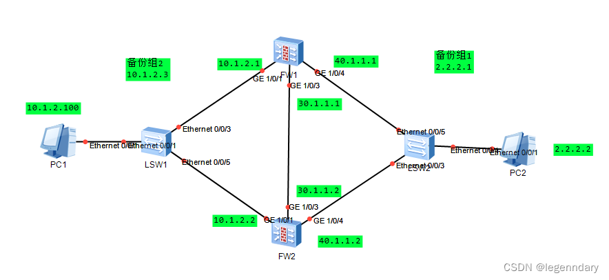
- 实验拓扑
2.实验步骤
步骤 1 完成 USG6330-1 上、下行业务接口的配置。配置各接口 IP 地址并加入相应安全区域。
<USG6330-1> system-view
[USG6330-1] interface GigabitEthernet 1/0/1
[USG6330-1-GigabitEthernet1/0/1] ip address 10.1.2.1 255.255.255.0
[USG6330-1-GigabitEthernet1/0/1] quit
[USG6330-1] interface GigabitEthernet 1/0/4
[USG6330-1-GigabitEthernet1/0/3] ip address 40.1.1.1 255.255.255.0
[USG6330-1-GigabitEthernet1/0/3] quit
[USG6330-1] firewall zone trust
[USG6330-1-zone-trust] add interface GigabitEthernet 1/0/1
[USG6330-1-zone-trust] quit
[USG6330-1] firewall zone untrust
[USG6330-1-zone-untrust] add interface GigabitEthernet 1/0/4
[USG6330-1-zone-untrust] quit
配置接口 GigabitEthernet 1/0/4 的 VRRP 备份组 1,并加入到状态为 Active 的 VGMP 管理组。
[USG6330-1] interface GigabitEthernet 1/0/4
[USG6330-1-GigabitEthernet1/0/4] vrrp vrid 1 virtual-ip 2.2.2.1 255.255.255.0 active
[USG6330-1-GigabitEthernet1/0/1] quit
配置接口 GigabitEthernet 1/0/1 的 VRRP 备份组 2,并加入到状态为 Active 的 VGMP 管理组。
[USG6330-1] interface GigabitEthernet 1/0/1
[USG6330-1-GigabitEthernet1/0/1] vrrp vrid 2 virtual-ip 10.1.2.3 active
[USG6330-1-GigabitEthernet1/0/1] quit
步骤 2 完成 USG6330-1 的心跳线配置。
配置 GigabitEthernet1/0/3 的 IP 地址。
[USG6330-1] interface GigabitEthernet1/0/3
[USG6330-1-GigabitEthernet1/0/3] ip address 30.1.1.1 255.255.255.0
[USG6330-1-GigabitEthernet1/0/3] quit
配置 GigabitEthernet1/0/3 加入 DMZ 区域。
[USG6330-1]firewall zone dmz
[USG6330-1-zone-dmz]add interface GigabitEthernet1/0/3
[USG6330-1-zone-dmz]quit
指定 GigabitEthernet1/0/3 为心跳口。
[USG6330-1] hrp interface GigabitEthernet1/0/3
步骤 3 配置 Trust 区域和 Untrust 区域的域间转发策略。
配置 Trust 区域和 Untrust 区域的域间转发策略。
HRP_A[USG6330-1]security-policy
HRP_A[USG6330-1-policy-security] rule name policy_sec
HRP_A[USG6330-1-policy-security-rule-policy_sec] source-zone trust
HRP_A[USG6330-1-policy-security-rule-policy_sec] destination-zone untrust
HRP_A[USG6330-1-policy-security-rule-policy_sec] action permit
HRP_A[USG6330-1-policy-security-rule-policy_sec] quit
步骤 4 启用 HRP 备份功能。
[USG6330-1] hrp enable
步骤 5 配置 USG6330-2。
USG6330-2 和上述 USG6330-1 的配置基本相同,不同之处在于:
1. USG6330-2 各接口的 IP 地址与 USG6330-1 各接口的 IP 地址不相同。
2. USG6330-2 的业务接口 GigabitEthernet1/0/1 GigabitEthernet1/0/4 加入状态为 Standby 的VGMP 管理组。
步骤 6 配置 Switch。
分别将两台 Switch 的三个接口加入同一个 VLAN。
3.结果验证
在处于 Trust 区域的 PC1 端 ping VRRP 组 2 的虚拟 IP 地址 10.1.2.3,在 USG6330-1 上检查会话 。可以看出 VRRP 组配置正确后,在 PC1 端能够 ping 通 VRR组 2 的虚拟 IP 地址。
PC2 作为服务器位于 Untrust 区域。在 Trust 区域的 PC1 端能够 ping 通 Untrust 区域的服务器。分别在 USG6330-1 和USG6330-2 上检查会话。可以看出 USG6330-2 上存在带有 Remote 标记的会话,表示配置双机热备功能后,会话备份成功。在 PC1 上执行 ping 2.2.2.2 –t ,然后将 USG6330-1 防火墙 G1/0/1 接口网线拨出,观察防火墙状态切换及 ping 包丢包情况;再将 USG6330-1 防火墙 G1/0/1 接口网线恢复,观察防火墙状态切换及 ping 包丢包情况。
具体测试截图,ensp配置文件可私信获取


 2212
2212


 被折叠的 条评论
为什么被折叠?
被折叠的 条评论
为什么被折叠?
 到【灌水乐园】发言


