


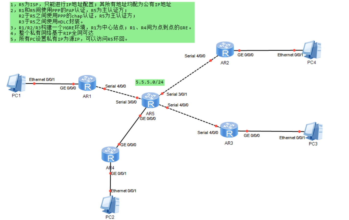
 该文详细描述了网络设备的IP地址规划,包括PC和路由器的地址设置。接着,介绍了PAP和CHAP两种PPP认证方式的配置。此外,文中还涉及了缺省路由设定、NAT出站转换、HDLC封装以及MGRE和GRE隧道的建立。最后,讲解了在不同环境下RIP路由协议的配置,以确保全网可达。

实验步骤:
第一步:IP地址规划
PC地址
| 设备 | 地址 | 网关 |
| PC1 | 192.168.1.2/24 | 192.168.1.1/24 |
| PC2 | 192.168.2.2/24 | 192.168.2.1/24 |
| PC3 | 192.168.3.2/24 | 192.168.3.1/24 |
| PC4 | 192.168.4.2/24 | 192.168.4.1/24 |
设备地址
| 设备 | 接口 | 地址 |
| R1 | S4/0/0 | 15.1.1.1/24 |
| R2 | S4/0/0 | 25.1.1.2/24 |
| R3 | S4/0/0 | 35.1.1.3/24 |
| R4 | S4/0/0 | 45.1.1.4/24 |
| R5 | S4/0/0 | 15.1.1.5/24 |
| S4/0/1 | 25.1.1.5/24 | |
| S3/0/0 | 35.1.1.5/24 | |
| G0/0/0 | 45.1.1.5/24 | |
| loopback0 | 5.5.5.5/24 |
第二步:配置IP地址
R1配置
[R1]interface g0/0/0
[R1-GigabitEthernet0/0/0]ip address 192.168.1.1 24
[R1]interface s4/0/0
[R1-Serial4/0/0]ip address 15.1.1.1 24
R2配置
[R2]interface g0/0/0
[R2-GigabitEthernet0/0/0]ip address 192.168.4.1 24
[R2]interface s4/0/0
[R2-Serial4/0/0]ip address 25.1.1.2 24
R3配置
[R3]interface g0/0/0
[R3-GigabitEthernet0/0/0]ip address 192.168.3.1 24
[R3]interface s4/0/0
[R3-Serial4/0/0]ip address 35.1.1.3 24
R4配置
[R4]interface g0/0/0
[R4-GigabitEthernet0/0/0]ip address 45.1.1.4 24
[R4]interface g0/0/1
[R4-GigabitEthernet0/0/1]ip address 192.168.2.1 24
R5配置
interface Serial3/0/0
ip address 35.1.1.5 255.255.255.0
interface Serial4/0/0
ip address 15.1.1.5 255.255.255.0
interface Serial4/0/1
ip address 25.1.1.5 255.255.255.0
interface GigabitEthernet0/0/0
ip address 45.1.1.5 255.255.255.0
第三步:PAP认证
主认证方配置
[R5]aaa
[R5-aaa]local-user huawei password cipher huawei
[R5-aaa]local-user huawei service-type ppp
[R5]interface s4/0/0
[R5-Serial4/0/0]ppp authentication-mode pap
被认证方配置
[R1]interface s4/0/0
[R1-Serial4/0/0]ppp pap local-user huawei password cipher huawei
第四步:CHAP认证
主认证方配置
[R5]aaa
[R5-aaa]local-user huawei password cipher huawei
[R5-aaa]local-user huawei service-type ppp
[R5]interface s4/0/0
[R5-Serial4/0/0]ppp authentication-mode chap
被认证方配置
[R2]interface s4/0/0
[R2-Serial4/0/0]ppp chap user huawei
[R2-Serial4/0/0]ppp chap password cipher huawei
第五步:配置缺省路由
[R1]ip route-static 0.0.0.0 0 15.1.1.5
[R2]ip route-static 0.0.0.0 0 25.1.1.5
[R3]ip route-static 0.0.0.0 0 35.1.1.5
[R4]ip route-static 0.0.0.0 0 45.1.1.5
第六步:NAT
[R1]acl 2000
[R1-acl-basic-2000]rule 1 permit source any
[R1-acl-basic-2000]q
[R1]inter s4/0/0
[R1-Serial4/0/0]nat outbound 2000

第七步:HDLC封装
[R3]inter s4/0/0
[R3-Serial4/0/0]link-protocol hdlc[R5]interface s3/0/0
[R5-Serial3/0/0]link-protocol hdlc
第八步:R1R2R3构建MGRE环境
R1配置
[R1]interface Tunnel 0/0/0
[R1-Tunnel0/0/0]ip address 10.1.1.1 24
[R1-Tunnel0/0/0]tunnel-protocol gre p2mp
[R1-Tunnel0/0/0]source 15.1.1.1
[R1-Tunnel0/0/0]nhrp network-id 100
R2配置
[R2]interface Tunnel 0/0/0
[R2-Tunnel0/0/0]ip address 10.1.1.2 24
[R2-Tunnel0/0/0]tunnel-protocol gre p2mp
[R2-Tunnel0/0/0]source s4/0/0
[R2-Tunnel0/0/0]nhrp entry 10.1.1.1 15.1.1.1 register
[R2-Tunnel0/0/0]nhrp network-id 100
R3配置
[R3]interface Tunnel 0/0/0
[R3-Tunnel0/0/0]ip address 10.1.1.3 24
[R3-Tunnel0/0/0]tunnel-protocol gre p2mp
[R3-Tunnel0/0/0]source s4/0/0
[R3-Tunnel0/0/0]nhrp entry 10.1.1.1 15.1.1.1 register[R3-Tunnel0/0/0]nhrp network-id 100
环境构建完成

第九步:R1R4配置GRE
R1配置
[R1]interface Tunnel 0/0/1
[R1-Tunnel0/0/1]ip address 20.1.1.1 24
[R1-Tunnel0/0/1]tunnel-protocol gre
[R1-Tunnel0/0/1]source 15.1.1.1
[R1-Tunnel0/0/1]destination 45.1.1.4
R4配置
[R4]interface Tunnel 0/0/1
[R4-Tunnel0/0/1]ip address 20.1.1.2 24
[R4-Tunnel0/0/1]tunnel-protocol gre
[R4-Tunnel0/0/1]source 45.1.1.4
[R4-Tunnel0/0/1]destination 15.1.1.1
GRE配置完成

第十步:书写RIP路由
MGRE环境下配置RIP路由
R1配置
[R1]rip 1
[R1-rip-1]version 2
[R1-rip-1]network 192.168.1.0
[R1-rip-1]network 10.0.0.0
注意:MGRE环境下RIP需要开启伪广播和关闭水平分割
[R1]interface Tunnel 0/0/0
[R1-Tunnel0/0/0]nhrp entry multicast dynamic //开启伪广播
[R1-Tunnel0/0/0]undo rip split-horizon //关闭水平分割
R2配置
[R2]rip 1
[R2-rip-1]version 2
[R2-rip-1]network 192.168.4.0
[R2-rip-1]network 10.0.0.0
R3配置
[R3]rip 1
[R3-rip-1]version 2
[R3-rip-1]network 192.168.3.0
[R3-rip-1]network 10.0.0.0
GRE环境下配置
R1配置
[R1]rip 1
[R1-rip-1]version 2
[R1-rip-1]network 20.0.0.0
R4配置
[R4]rip 1
[R4-rip-1]version 2
[R4-rip-1]network 192.168.2.0[R4-rip-1]network 20.0.0.0
测试实现全网可达 PC1 ping PC2 、PC3和PC4


 649
649

 被折叠的 条评论
为什么被折叠?
被折叠的 条评论
为什么被折叠?
 到【灌水乐园】发言


